When we discuss the exciting current in a transformer, everything begins with understanding how a transformer actually works. Let me walk through the basics in plain language.
Basic Mutual Induction in a Transformer
A transformer is just two (or more) windings wrapped around a magnetic core:
Primary winding – connected to the AC supply (input side)
Secondary winding – connected to the load (output side)
Magnetic core – usually CRGO steel in modern power and distribution transformers
The real magic is mutual induction:
AC voltage on the primary creates an alternating current
That current sets up an alternating magnetic flux in the core
The changing flux links the secondary winding
That changing flux induces a voltage in the secondary (Faraday’s law)
No moving parts, just a magnetic field doing the work.
Core, Windings, and Alternating Magnetic Flux
Here’s the energy path in simple terms:
1. AC voltage → primary current
2. Primary current → alternating flux (Φ) in the core
3. Flux links both windings → induced EMF in primary and secondary
Key points:
The core is designed so that most of the flux is confined and guided through it
The flux is alternating at the same frequency as the supply (50/60 Hz)
The induced EMF in each winding is proportional to turns × rate of change of flux
That’s why the turns ratio sets the voltage ratio.
No-Load vs. Loaded Operation
Now, what changes between no-load and load?
No-load condition
Secondary is open-circuited (nothing connected)
No load current flows in the secondary
But the core still needs magnetizing to set up flux
Loaded condition
The load is connected to the secondary
Secondary current flows and creates its own opposing flux
The primary draws extra current to balance this and supply real power
Even with no load, the transformer is not “off.” It’s energized, building flux, and drawing a small but important current from the supply.
Why Does Primary Current Flow with an Open Secondary?
This is where people get confused.
You might think: If the secondary is open, no power is delivered… so why is there current in the primary at all?
Because the primary still has to:
Establish the alternating magnetic flux in the core
Overcome core losses (hysteresis and eddy current losses) in the steel
To do that, it must draw:
A small magnetizing current to create flux
A small core loss current to pay for iron losses
This small total current at no-load is what we later call exciting (or excitation) current. Even with the secondary open, the primary is “working” to keep the core magnetized and cover no-load losses.
What Is Exciting Current in a Transformer?

Simple definition of exciting current
Exciting current (also called excitation current or no-load current) is the small amount of AC that flows in the primary winding of a transformer when the secondary is open-circuited (no load connected) and the rated voltage is applied.
It’s the current needed just to establish the magnetic flux in the core, even when the transformer isn’t delivering power to any load.
Why exciting current exist at no-load
Even at no load, the transformer core has to:
Build and maintain the magnetic field (magnetizing current)
Cover core losses like hysteresis and eddy current losses (core loss current)
That means the primary still draws current from the grid. This is one reason distribution and power pole transformers on US lines consume energy even when lightly loaded, which matters for long-term energy costs and grid efficiency. If you want the bigger picture of how these units sit in a system, it helps to see how they fit into a power grid layout like the one described in this guide on how to understand power grids.
Typical exciting current range in real transformers
For most practical transformers operating at rated voltage and frequency:
Power and distribution transformers: exciting current is usually about 1%–5% of rated full-load current
High-quality, low-loss designs in the US market often sit toward the lower end of that range, especially where energy codes and utility penalties push for better efficiency
Exciting current vs full-load current
Compare it this way:
Exciting current (Io):
Flows at no-load
Mainly reactive (magnetizing) with a small active part (core loss)
Typically very small compared to rated current
Full-load current (rated current):
Flows when the transformer is fully loaded
Includes both load current (to supply kW to the load) and the small exciting current
Dominates conductor sizing, breaker ratings, and protection settings
In practice, exciting current is what keeps the core “alive” magnetically, while full-load current is what actually feeds your equipment or the downstream grid.
Components of Exciting Current in a Transformer
When I talk about exciting current (Io) in a transformer, I always break it into two key parts. This makes troubleshooting, testing, and protection settings much easier.
Magnetizing Current Im (Reactive Component)
Im is the magnetizing current – it creates the AC magnetic flux in the core.
It lags the applied voltage by almost 90°, so it’s mainly reactive (VAR), not real power.
Im depends on:
Core material and design
Voltage and frequency (higher voltage or lower frequency → higher Im and risk of saturation)
In a healthy power or distribution transformer, Im is usually small compared to full-load current, but it dominates the reactive part of the no-load current.
Core Loss Current Ic or Iw (Active Component)
Ic (or Iw) is the core loss current – it represents real power used to cover:
Hysteresis loss
Eddy current loss in the core
Ic is in phase with the applied voltage, so it’s the active (watt) component of exciting current.
It’s directly tied to no-load power loss P₀, using:
P₀ ≈ V × Ic (for a single-phase transformer or per phase).Utilities and industrial users in the U.S. care about Ic because it’s what they pay for 24/7, even when the transformer is lightly loaded.
Resultant Exciting Current Io (Vector Sum)
The total exciting current Io is the vector sum of Im and Ic:
Io = √(Im² + Ic²)Since Im and Ic are at roughly 90° to each other, Io lags the voltage, but not as much as Im alone.
On a phasor diagram described in words:
Draw the voltage V as a horizontal reference.
Ic is drawn in line with V (same direction – active component).
Im is drawn straight down, 90° behind V (purely inductive).
Io is the diagonal from the origin to the tip of the Ic–Im right triangle – this is the actual no-load or exciting current.
Understanding this split between Im and Ic is key when you’re setting up transformer protection or coordinating with upstream devices like switchgear and circuit breakers in medium-voltage systems, where accurate no-load behavior matters just as much as fault behavior.
Exciting current waveform and harmonics

In a real transformer, the exciting current waveform (no-load current) is not a clean sine wave. Even though we apply a sinusoidal voltage, the exciting current gets distorted and contains harmonics, especially the third harmonic and other odd harmonics (5th, 7th, etc.).
Why exciting current is not purely sinusoidal
The main reason is the nonlinear B–H curve of the core steel. In simple terms:
At low flux, the core is easy to magnetize → small current.
As flux increases toward saturation, the core suddenly needs much more current for a small increase in flux.
This “bent” B–H curve means the magnetizing current spikes near the voltage peaks, so the current waveform becomes peaky and non-sinusoidal.
Effect of nonlinear B–H curve
Because of this nonlinearity:
The magnetizing current has a strong reactive component (lagging 90°) that is distorted.
Fourier analysis of this distorted current shows:
Fundamental component (50/60 Hz) – what we design for.
Odd harmonics – mostly 3rd, then 5th, 7th, etc.
Third harmonic and odd harmonics
Key points about harmonics in exciting current:
Third harmonic current is usually the largest harmonic in the excitation current.
These harmonics:
Increase core losses (eddy + hysteresis).
Can cause extra heating in windings and nearby metal parts.
May interfere with sensitive protection relays if not accounted for in design and settings.
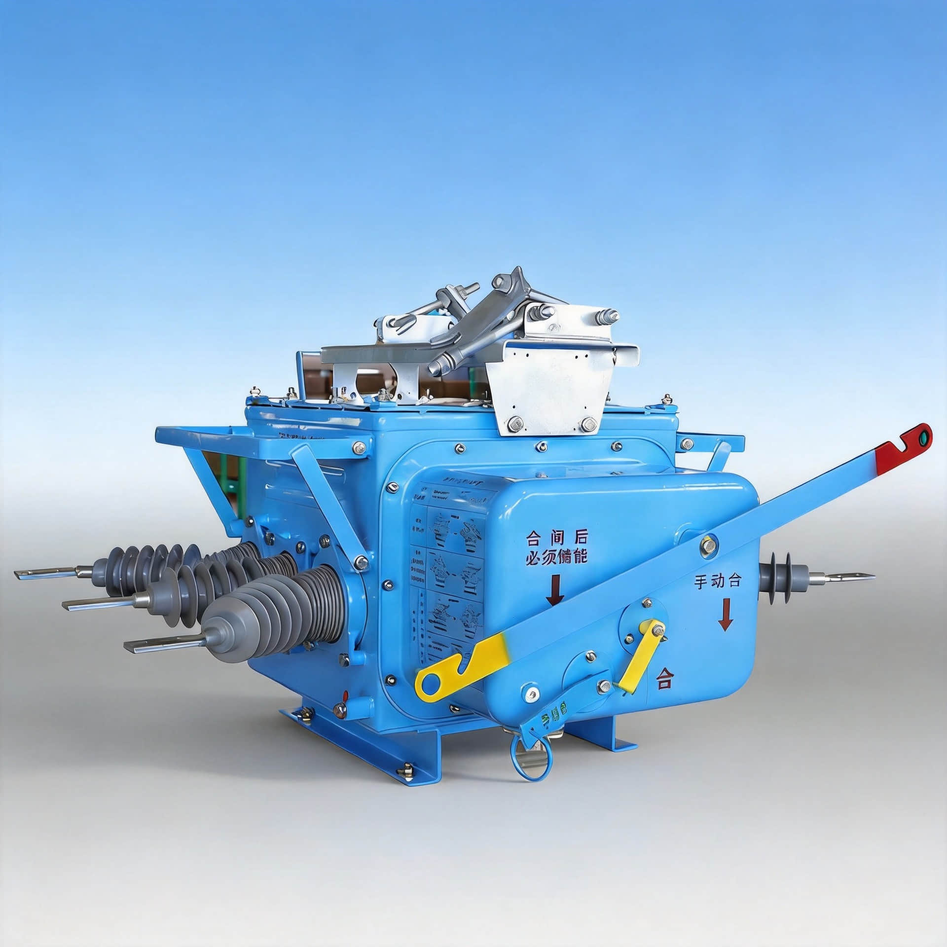
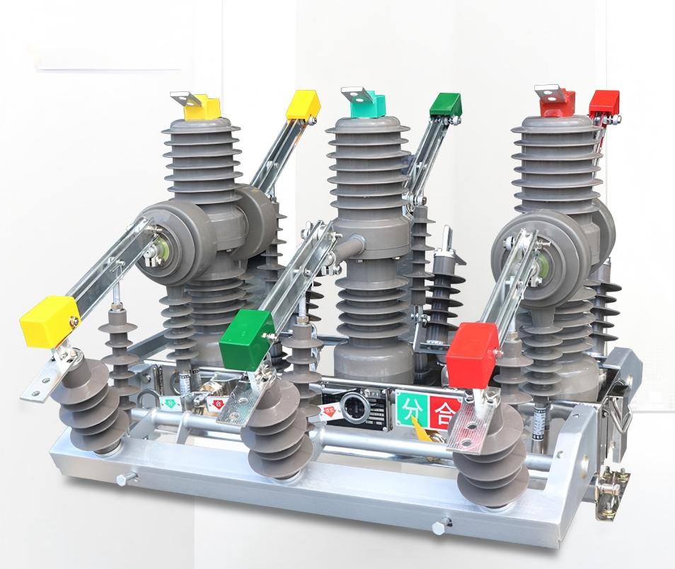
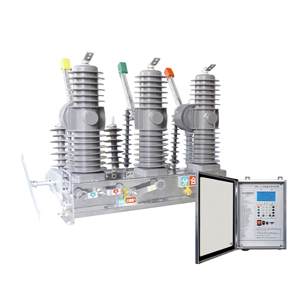
If you’re using modern protection with solid-state relays and vacuum circuit breakers on the primary side, you want devices designed to handle this harmonic-rich current without nuisance tripping, similar to how a properly specified vacuum circuit breaker is selected for transformer duties.
Impact on neutral and circulating currents
In three-phase transformers, third-harmonic behavior is critical:
In a Y-connected winding with neutral, third-harmonic exciting current is in phase in all three phases, so it:
Adds up in the neutral → high neutral current if the neutral is solidly grounded.
In delta windings, third-harmonic currents circulate inside the delta:
This traps most third-harmonic current, reducing it on the line side.
But it also creates circulating currents and heating inside the delta.
This is why transformer designers and system planners in US power systems pay close attention to winding connections, neutral grounding, and switching gear selection, especially when installing or upgrading medium-voltage indoor gear like VCBs and disconnects in substations or industrial plants.
Exciting Current vs Inrush Current in a Transformer
Steady‑State Exciting Current (No‑Load Current)
In steady state, exciting current (also called no‑load current) is the small current the transformer draws from the supply with the secondary open and voltage at its rated value.
It mainly does two jobs:
Creates the magnetic flux in the core (magnetizing current)
Covers core losses (hysteresis + eddy current losses)
Typical values:
Usually 1–5% of rated full‑load current in power and distribution transformers
Stable and almost constant as long as voltage and frequency are normal
What Is Magnetizing Inrush Current?
Magnetizing inrush current is the very high, short‑duration current that flows right when you energize a transformer, even with no load on the secondary. It’s a transient, not a normal operating current.
Key causes:
Residual flux in the core from previous operation
Switching the transformer at a point on the voltage waveform that drives the core deep into saturation
Once saturated, the core can’t carry more flux linearly, so the current spikes to force the flux level
Residual Flux and Core Saturation
Inrush current gets serious when:
The core still has residual magnetism (flux not fully gone after de‑energization)
The new switching instant pushes total flux above the normal design level, driving the core into saturation
In saturation, inductive reactance collapses, so current is limited mostly by winding resistance and system impedance
Result: Short burst of huge current until the flux settles into a normal sinusoidal pattern.
Magnitude and Duration: Exciting vs Inrush
Compare the two:
Exciting current (Io)
Magnitude: ~1–5% of rated current
Duration: Continuous during normal energized, no‑load operation
Shape: Distorted but stable waveform
Inrush current
Magnitude: typically 8–14 × rated current, sometimes higher
Duration: From a few cycles to a few seconds, decaying as flux stabilizes
Shape: Highly distorted, rich in low‑frequency and odd harmonics
Inrush is a startup event; exciting current is a steady‑state condition.
Protection Relay Issues: Inrush vs Exciting Current
For medium and high‑voltage transformers in the U.S., proper relay coordination is critical so protection doesn’t trip on harmless inrush.
Main challenges:
Inrush current looks like a massive internal fault if you only look at RMS magnitude.
To avoid nuisance trips, modern transformer differential relays use:
Harmonic restraint (especially 2nd harmonic) to tell inrush from real faults
Time delay and slope settings tuned to expected inrush behavior
Steady‑state exciting current is small and normally ignored by protection; however, abnormally high excitation current at no load can indicate:
Core problems (shorted laminations, saturation from overvoltage)
Winding or insulation issues
When we design or specify transformer systems and upstream switchgear in our projects, we always match protection settings and breaker characteristics to expected inrush peaks and normal exciting current, similar to how you’d coordinate transformer behavior with upstream switchgear and circuit breaker performance as discussed in this switchgear performance and safety guide.
Exciting current formula and calculation
In a transformer, the exciting current (Io) at no-load is made of two parts:
Magnetizing current (Im) – creates the magnetic flux (reactive component)
Core loss current (Ic or Iw) – represents real power loss in the core (active component)
Because these two components are 90° apart in phase (ideally), we calculate the total exciting current as a vector sum:
Io = √(Im² + Ic²)
This is the key exciting current formula used in transformer design, testing, and protection settings.
Voltage and frequency effect on exciting current
For a given transformer:
Flux (Φ) ∝ V / f
If voltage (V) increases at the same frequency, core flux rises, pushing the core toward saturation and exciting current increases sharply.
If frequency (f) drops at the same voltage, flux increases, again driving up magnetizing current Im.
That’s why in U.S. grids (60 Hz), running a 50 Hz transformer at 60 Hz often reduces exciting current, and the opposite can be risky.
Always keep operating V and f close to nameplate values to keep exciting current within design limits.
Core loss current and no-load power loss
The core loss current Ic is tied directly to no-load power loss P0:
P0 ≈ V × Ic (for single-phase, or √3 × V × Ic for three-phase)
P0 includes hysteresis and eddy current losses in the core.
For a given voltage, if Ic is high, your no-load losses are high, which means wasted energy 24/7, especially painful on large distribution or power transformers that stay energized all the time.
This is exactly what we measure in an open-circuit (no-load) test, which is also key when selecting and sizing equipment like switchgear and high voltage insulators around the transformer.
Design factors that change exciting current
As a manufacturer and system designer, I control exciting current mainly through:
Core material
High-grade CRGO steel or better materials → lower losses and lower Io
Core cross-section and flux density
Designing for lower flux density → lower magnetizing current, less risk of saturation
Core joint and lamination quality
Tight joints and thin, well-insulated laminations → reduced hysteresis and eddy losses → lower Ic
Operating voltage window
Designing and specifying transformers to handle expected U.S. grid overvoltages with margin, so exciting current doesn’t spike under real conditions.
When I size or recommend a transformer for U.S. commercial or industrial users, I’m always looking at no-load loss and exciting current together, because they directly impact energy bills, efficiency, and long-term reliability of the whole system.
Exciting Current Measurement and Tests
Open-circuit (no-load) test for transformers
To measure transformer exciting current, I always start with a simple open‑circuit test:
Apply rated voltage to the primary with the secondary completely open.
Measure: no-load current (Io), no-load power (P0), and applied voltage (V).
This gives you excitation current, core losses, and tells you how “healthy” the core is.
On larger systems, I recommend using good-quality meters and, when needed, external current transformers to keep measurements safe and accurate—similar to how we design our own precision current transformers for stable, low‑distortion sensing.
How to measure excitation current safely
Safety and consistency matter more than the numbers themselves:
Use a variable AC source (or variac) so you can ramp voltage slowly from 0 to rated value.
Connect a true RMS ammeter in series with the primary winding.
Make sure:
The secondary is securely open or shorted as per the test method.
The transformer tank and test bench are properly grounded.
You stay within the nameplate voltage and frequency unless you’re doing a controlled over‑excitation check.
Finding winding or core faults with excitation current
Abnormal excitation current is often the first flag that something is wrong:
Higher than normal Io at rated voltage:
Possible core damage, partial shorted turns, or over‑fluxing.
Asymmetrical or distorted current waveform:
Localized core saturation, mechanical movement, or poor joints in the core.
Phase-to-phase comparison (3‑phase units):
If one phase draws much higher excitation current than the others, suspect a winding or core leg fault in that phase.
When we test transformers for customers, we log excitation current vs voltage and compare it to factory data. Any big deviation gets investigated before energizing the unit in the field.
Typical excitation current patterns in three‑phase cores
For three‑phase transformers, the pattern of exciting current tells a story:
In a healthy core:
All three phases have similar Io at rated voltage (within a tight tolerance).
Harmonics are present but balanced, so neutral current in a grounded‑wye system is controlled.
In a problem core:
One phase may show steeper current rise with voltage (earlier saturation).
Neutral current may be unexpectedly high due to unbalanced third harmonics.
If you’re testing multiple units in a substation or plant, keeping a simple spreadsheet of exciting current per phase at a few voltage points (e.g., 50%, 80%, 100%) is an easy way to spot outliers before they cause trips, overheating, or misoperation of protection.
Factors Affecting Exciting Current in a Transformer

Core Material and CRGO Steel
The core material is the first thing that sets the exciting current level.
CRGO (Cold Rolled Grain Oriented) steel has high permeability and low losses, so it needs less exciting current to build the same flux.
Cheaper or lower‑grade steel drives the core closer to saturation, so no‑load (excitation) current and harmonics go up, and efficiency goes down.
For medium- and high-voltage networks in the U.S., I always recommend pairing low-loss core designs with reliable upstream protection, like HV drop-out protection using a RW3 drop-out high voltage fuse or similar, so nuisance trips from abnormal excitation behavior are avoided.
Voltage Variation and Overvoltage
Exciting current is very sensitive to supply voltage.
At rated voltage, exciting current stays low and predictable.
With overvoltage, core flux shoots up, the core moves into saturation, and exciting current can increase sharply and become highly distorted.
Even a 5–10% overvoltage can noticeably raise no‑load losses and heating in power and distribution transformers.
Frequency Changes and Flux Density
Flux density in the core is roughly proportional to V / f.
If frequency drops (but voltage stays the same), flux density rises, the core moves closer to saturation, and exciting current increases.
At higher frequency, for the same voltage, flux density falls and exciting current tends to decrease, but eddy current losses can climb if the core isn’t designed for that frequency.
For grid and substation gear, we usually match transformers strictly to 60 Hz service; running outside that window for long periods is a red flag.
Temperature, Aging, and Insulation Condition
Over time, exciting current gives you a quiet snapshot of transformer health.
Higher temperature increases core and winding resistance slightly but can also indicate higher no‑load losses driven by increased exciting current.
Aging and insulation degradation (moisture, partial discharges, local hot spots) can change the magnetizing path and introduce localized saturation, which shows up as abnormal excitation current patterns.
Sudden increases in exciting current at the same voltage and frequency usually point to core problems, winding deformation, or insulation issues and call for testing and possibly isolation with an indoor disconnect, such as a GN19-12M indoor disconnect switch in switchgear lineups.
Keeping voltage and frequency within spec, using high-grade CRGO cores, and watching trends in excitation current is how I keep transformers efficient, cool, and reliable over the long haul.
Why exciting current matters in transformer performance

In real-world systems, exciting current in a transformer isn’t just a theory point—it directly affects cost, efficiency, and protection settings.
Effect on transformer no-load losses
Exciting current has two parts:
Magnetizing current (reactive) – builds the core flux
Core loss current (active) – causes real power loss (hysteresis + eddy loss)
That core loss current is what drives no-load losses. Even with the secondary open, the transformer pulls power from the grid and turns it into heat. For utilities and large U.S. industrial users, this shows up as:
Higher standby energy bills
Extra heating in the core and tank
More stress on cooling systems
On distribution or power units, managing no-load losses is a big part of lifecycle cost, and it ties directly to how low we can keep the exciting current.
Impact on efficiency and energy savings
Lower exciting current = lower no-load losses = better efficiency at light load.
This matters when:
Transformers run lightly loaded most of the time (common in commercial buildings, campuses, and backup systems)
You operate 24/7 and every watt of core loss adds up over years
For U.S. projects chasing energy codes and utility rebates, choosing low exciting current / low-loss designs is one of the easiest long-term savings wins.
Influence on voltage regulation at light load
Exciting current is mostly reactive, so it affects:
Primary current and voltage drops in upstream feeders
Secondary voltage at very light load
If exciting current is high, the transformer “looks” more reactive to the system, which can slightly worsen voltage regulation when the load is small. For sensitive equipment (IT loads, automation gear, medical devices), tighter regulation at light load is a real advantage.
Role in protection settings and relay coordination
Protection relays and medium-voltage switchgear need to “see” what’s normal and what’s a fault. Steady-state exciting current sets the baseline:
Overcurrent and differential relays must ignore normal excitation current but trip on faults
High or unbalanced exciting current can signal core problems or winding issues, which is why excitation tests are part of condition assessment
When paired with devices like vacuum circuit breakers in medium-voltage gear, accurate knowledge of exciting current helps avoid nuisance trips and improves relay coordination
For context, you’ll often see these topics come up in relay vs. breaker applications and medium-voltage protection design, like those used in modern medium-voltage switchgear lineups.
Modern low exciting current design trends
Modern transformer designs in the U.S. push hard for lower exciting current to hit efficiency and regulatory targets:
Use of high-grade CRGO steel and better lamination stacks
Optimized core cross-section to avoid unnecessary flux density
Better manufacturing control to reduce joints and gaps that raise magnetizing current
The payoff is clear:
Lower no-load losses and operating cost
Cooler, more reliable operation
Easier relay coordination and cleaner power quality at light load
For utilities, EPCs, and facility owners, specifying low-exciting-current, low-loss transformers is now standard practice in new projects and replacements.
Common Questions About Exciting Current in a Transformer
Is exciting current constant at no load?
No, exciting (no-load) current is not perfectly constant, even at no load.
It changes slightly with:
Voltage (higher voltage → higher exciting current)
Frequency (lower frequency → higher flux → higher exciting current)
Temperature and core condition
In practice, on a stable grid in the U.S. (60 Hz, steady voltage), the exciting current is almost steady, but not mathematically constant.
Exciting current vs leakage current vs load current
Use this table to keep the terms straight:
| Term | What it is | When it flows | Size (typical) |
|---|---|---|---|
| Exciting current | Current that magnetizes the core + covers core losses | At no load and under load | ~1–5% of rated current (steady-state) |
| Leakage current | Current linked with leakage flux that doesn’t fully couple primary & secondary | Under load (depends on load) | Small, but tied to leakage reactance |
| Load current | Current drawn by the load on the secondary | Only when load is connected | Up to rated current or nameplate |
You size cables, breakers, and protection mainly for load current, not for exciting current.
Why is exciting current confused with inrush current?
Because both happen with “no load” on the secondary, but they are totally different:
Exciting current
Steady-state, small (1–5% of rated current)
Flows all the time whenever the transformer is energized
Predictable and almost sinusoidal (with some harmonics)
Inrush current
Short-duration, very high (can reach 8–12 × rated current)
Happens when you energize the transformer
Caused by core saturation and residual flux
Highly distorted waveform and rich in harmonics
A key cause of nuisance breaker trips and protection misoperation, similar to the issues discussed when troubleshooting circuit breaker tripping under high inrush.
People see a current spike at energization and just call it “exciting current,” but technically that spike is magnetizing inrush, not the normal exciting current.
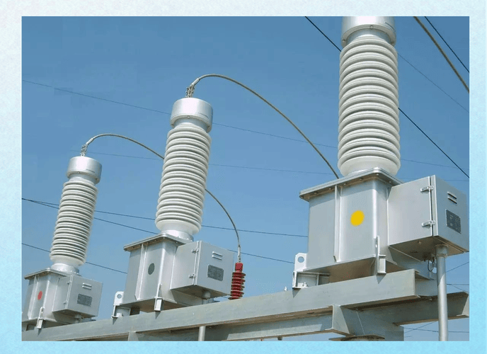
Practical examples: power vs distribution transformers (U.S. use cases)
1. Small pole-mounted distribution transformer (25–50 kVA, 13.2 kV / 240 V)
Rated HV current: a few amps
Exciting current: maybe 0.1–0.3 A on the HV side
You’ll see a brief inrush spike when a fuse cutout or recloser closes, then it settles into a small, steady exciting current.
2. Medium power transformer in a substation (10–40 MVA)
Rated HV current: hundreds to a few thousand amps
Steady exciting current: still just 1–3% of rated current
Inrush current on energization can be 10× rated current for a few cycles, which is why utilities pair these with properly set vacuum circuit breakers and auto-reclosers (for example, a pole-mounted auto-recloser) to ride through inrush without false trips.
If you’re specifying or troubleshooting transformers in the U.S., you always treat:
Exciting current as a continuous, efficiency and loss issue
Inrush current as a protection, breaker, and coordination issue