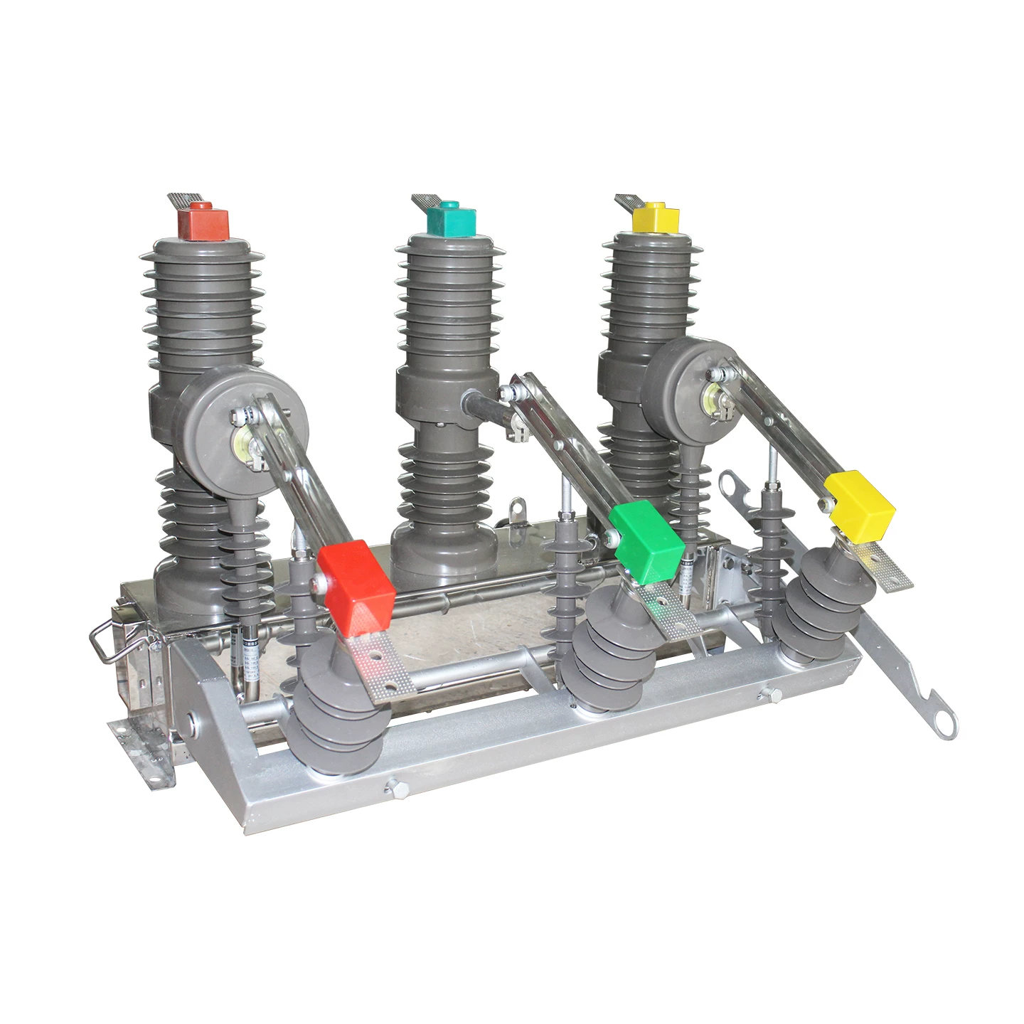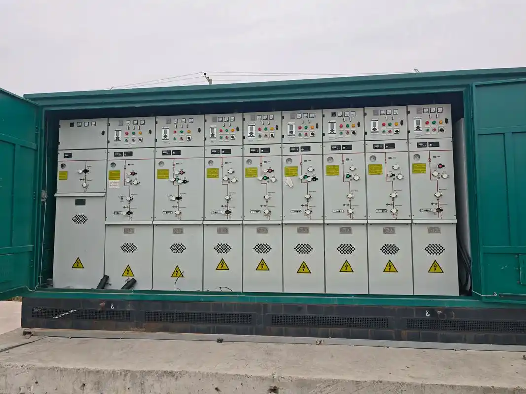
A ring main unit (RMU) is a metal-enclosed medium voltage switchgear system that integrates switching, protection, control, and monitoring into one compact assembly for ring network power distribution. In plain engineering terms, it is the equipment that lets two power sources support the same distribution area with high reliability, and if you read this article carefully, you will know how to judge an RMU layout, identify its key parts, and analyze its fault logic by yourself.
One correction is necessary at the start: RMUs are not only 10kV equipment. The most common field class is 10kV/12kV, but 24kV, 33kV, and 35kV/36kV RMUs are also widely used in industrial projects, renewables, export markets, and utility applications. By contrast, 0.4kV low-voltage systems are not called RMUs; they are called distribution boards, switchboards, motor control centers, or power cabinets.
I have spent years walking distribution rooms, substation basements, and compact prefabricated transformer stations where the nameplate looked clean but the cable trench told the real story. In practice, engineers do not judge an RMU by brochures alone. They judge it by whether the open point is clear, whether the PT cabinet is alive, whether the DTU is actually communicating, whether the three-position switch interlock feels trustworthy, and whether the cable terminations stay dry through one humid summer.
Why Ring Main Units Matter in Electrical Distribution
The core problem an RMU solves is simple: radial feeders fail badly when one point goes wrong. If a single cable section, joint, or upstream switch fails in a radial arrangement, everyone downstream can lose supply.
RMU in power distribution improves continuity because the network is built as a ring. Even though it is usually operated with one normal open point, the loop structure allows operators to isolate a bad section and restore healthy sections from the alternate source much faster than in a pure radial design.
This is why utilities, industrial owners, and facility operators choose ring main unit electrical distribution when outage cost is high. The true value is not just compactness. The true value is controlled switching, selective isolation, and restoration speed.
Where RMUs Are Used in the Real World
RMUs are common in urban distribution loops, especially where underground cable networks dominate, and land is expensive. City utilities prefer compact, enclosed, low-footprint switching points that fit into basements, roadside kiosks, and package substations.
They are also standard in commercial buildings, industrial parks, data centers, renewable energy collection points, and transformer substations. In these settings, the RMU often acts as the switching node between incoming utility feeders and outgoing transformer feeders.
One practical note from site work: in data centers and premium commercial campuses, the discussion is rarely about whether an RMU can switch. The real discussion is whether the complete chain—PT supply, DC backup, communication gateway, protection setting, and cable accessory quality—can support reliable remote restoration under pressure.
RMU Voltage Classes: Not Only 10kV
A persistent misunderstanding in the field is that “RMU” means only 10kV. That is wrong. The term describes a switching concept and equipment form within medium-voltage distribution, not a single voltage class.
Mainstream Common Voltage Class: 10kV (12kV)
In many domestic utility and facility networks, more than 90% of commonly seen RMUs are 12kV-class equipment, usually referred to in daily engineering language as “10kV RMUs.” These are widely used in residential communities, municipal feeders, factories, commercial estates, and public infrastructure.
The equipment insulation level, switching duty, and protection arrangement are standardized enough that 10kV/12kV RMUs have become the default mental model for most technicians. This is why many low-voltage electricians first encounter medium-voltage practice through RMU operation and transformer feeder work.
High-Voltage RMUs Also Exist: 35kV (36kV)
35kV/36kV RMUs are very real and widely used. They appear in industrial parks, photovoltaic projects, wind power collector systems, and supporting roles around substations where a higher distribution voltage reduces current and feeder losses over distance.
In renewable projects, 35kV ring arrangements are especially common because multiple collection points must be linked with practical switching flexibility. Engineers who only work in municipal 10kV systems often underestimate how normal 35kV RMUs are in these sectors.
24kV RMUs
24kV RMUs are common in overseas projects, selected industrial applications, and markets where 24kV distribution standards are established. Export-oriented manufacturers often treat 24kV as a standard product line rather than a special order.
In mining, process plants, and international EPC projects, 24kV can be the practical compromise between feeder reach, equipment cost, and local grid standards.
33kV RMUs
33kV is a mainstream utility distribution voltage in many overseas regions, including parts of Africa, Southeast Asia, and the Middle East. As a result, 33kV RMUs are used in very large quantities and should never be treated as rare or exotic equipment.
Anyone involved in export power systems, utility consulting, or renewable evacuation projects sees this quickly. The misconception that RMUs only exist at 10kV mostly comes from people whose experience is limited to one national distribution standard.
No Low-Voltage RMU Concept at 0.4kV
At 0.4kV, the term RMU is generally not used. The correct terms are low-voltage distribution cabinet, switchboard, power cabinet, or motor control center.
This distinction matters because low-voltage switching philosophy, interrupting devices, enclosure design, and protection coordination are different. Calling a 0.4kV board an RMU is a terminology error and often signals confusion about voltage class and system architecture.
RMU at a Glance: Key Functions and Benefits
The value of ring main unit electrical distribution can be reduced to four practical advantages:
Compact footprint for dense installations
Safer enclosed operation than open arrangements
Faster fault isolation through sectional switching
Higher supply reliability than simple radial feeders
Compared with a broad medium voltage switchgear system, the RMU is purpose-built for compact distribution nodes, especially where ring-feeder logic and quick transfer matter more than elaborate busbar architectures.
Typical 10kV Ring Main Unit Configuration: 9-Panel Example
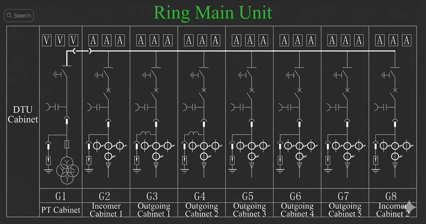
To explain the structure clearly, use a practical reference layout: one complete RMU lineup with 9 panels. This is not the only configuration in the field, but it is a very effective model for learning cabinet roles and switching logic.
DTU Cabinet on the Side
On one side sits the DTU cabinet. DTU means Distribution Terminal Unit, and this cabinet handles feeder automation, remote signaling, status acquisition, fault indication, and remote control.
In theory, the DTU is the brain that connects the RMU to SCADA or feeder automation systems. In reality, its usefulness depends completely on stable auxiliary power, working communication channels, correct point mapping, and disciplined commissioning.
Front Row: 1 PT Cabinet and 8 Main Cabinets
On the front are 8 main cabinets plus 1 PT cabinet. The PT cabinet provides voltage reference and control support, while the main cabinets carry the incoming and outgoing feeder functions.
A common arrangement is one PT cabinet and seven feeder-related cabinets, but in many practical lineups the exact order changes based on site cable direction, transformer position, and room geometry.
Two Incoming Feeders and Five Outgoing Feeders
A typical arrangement is two incoming feeders and five outgoing feeders, commonly called a two-in, five-out RMU. The two incomers handle the ring supply path, and the five outgoing feeders supply downstream loads such as transformers, buildings, pump stations, or process areas.
This arrangement is extremely common because it balances reliability with compactness. It is large enough to support local distribution branching but still small enough to fit into space-constrained distribution rooms.
Cable Routing and Panel Arrangement Principles
Good panel arrangement follows one field principle: make cable routing natural. Cables should not cross unnecessarily, bend excessively, or create impossible maintenance access.
The best installations are not just electrically correct. They are physically readable. When panel order follows actual feeder direction, fault tracing and future expansion become much easier.
How a Ring Network Is Formed
A standard ring network can be formed when two separate 110kV substations each provide one 10kV source into different RMU points. For example, one source enters RMU position 1, and another enters RMU position 6.
The intermediate RMUs are linked by cables, forming a loop. That is the physical ring. It does not mean every switch is closed all the time. The ring exists in topology first, operation second.
Ring Network Operation: Closed-Loop Topology, Open-Point Operation
The most important operating concept is this: the network is physically ring-connected but normally operated with one open point. Many non-specialists hear “ring network” and assume all switches are closed in normal service. That is usually incorrect.
Normal Operating Condition
Under normal operation, one switch in the ring remains open. This normal open point prevents unwanted parallel closure between sources, simplifies protection coordination, and limits fault current complexity.
The ring therefore behaves like two radial feeders back-to-back, while retaining the ability to transfer load later. This is one of the most misunderstood features of RMU systems.
Fault Condition and Supply Restoration
If a cable or feeder section faults, operators open the switches at both ends of the faulty section to isolate it. Then they close the normal open point so healthy sections can be fed from the alternate source.
This is the practical beauty of the RMU. A fault in one section does not automatically black out everyone else. Proper sectionalizing and transfer restore most loads quickly.
Why This Greatly Improves Reliability
The chief reliability advantage is selective continuity. One faulty segment can be sacrificed so the rest of the loop survives.
In utility terms, this improves service continuity indices. In factory terms, it prevents one cable failure from stopping every production line downstream. In data center terms, it can be the difference between a manageable switching event and a major outage escalation.
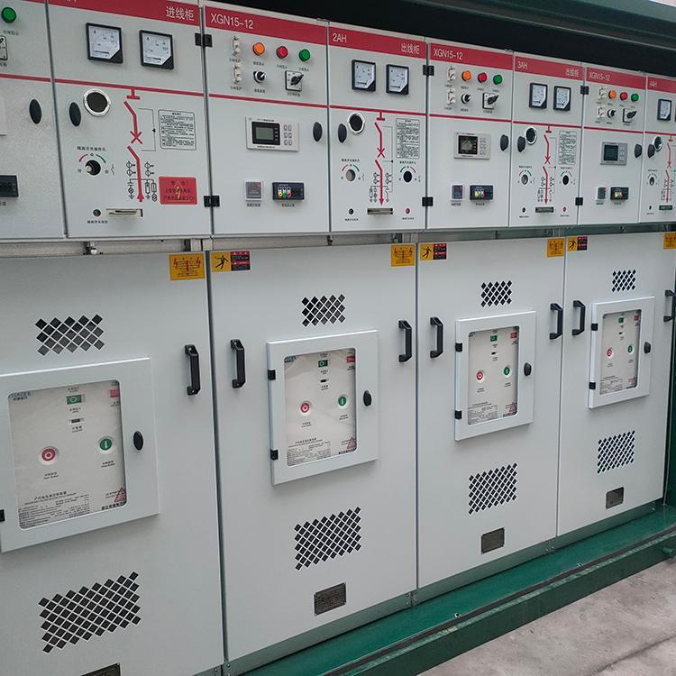
Core Components Inside a Ring Main Unit
To analyze an RMU like a technician, you must know what to identify on drawings and on site. Most troubleshooting mistakes happen because people know the cabinet label but do not understand the internal functional chain.
Gas Insulated Ring Main Unit
A gas-insulated ring main unit seals the switching devices inside a gas tank filled with insulating gas. Depending on design and environmental compliance strategy, manufacturers may use SF6 or alternative insulation technologies aligned with newer decarbonization pressures.
The advantages are compact size, strong environmental protection, reduced exposure of live parts, and easier installation in constrained spaces. In crowded urban substations, basement electrical rooms, and packaged transformer stations, this design is often the only practical choice.
From field experience, gas insulation reduces many contamination issues but does not magically eliminate maintenance risk. The weak points often move outward to operating mechanisms, cable accessories, interlocks, and auxiliary circuits.
Three-Position Switch: Isolate, Service, and Earth
The three-position switch is one of the most important compact mechanisms in an RMU. It combines the roles of isolation and earthing in a coordinated arrangement that saves space and helps prevent misoperation.
The three positions are:
Middle: fully disconnected, neither service nor earth engaged
Service position: isolator closed for energization
Earth position: earthing switch closed for safe maintenance
On many practical units, technicians describe this by handle direction: middle for full separation, right for service, left for earth. The exact physical indication varies by manufacturer, so never trust habit over the position diagram.
Safe Maintenance Switching Sequence
The standard safety sequence is straightforward and must be respected: open the circuit breaker, open the isolator, close the earthing switch, then begin maintenance only after verification.
This sequence is consistent with established medium-voltage safety principles and aligns with the spirit of IEC 62271 series requirements for high-voltage switchgear and controlgear, as well as widely adopted utility safe isolation procedures. A live-line indicator is useful, but it is never a substitute for approved test-before-touch practice.
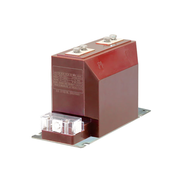
Current Transformers (CTs)
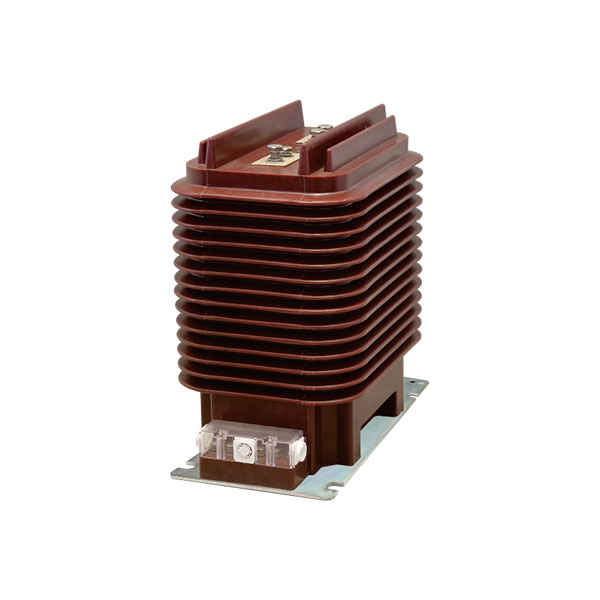
Modern 10kV RMUs commonly use three-phase CTs. Two-phase CT arrangements still exist in older systems, but three-phase configurations are now the practical norm for protection, measurement, and metering integration.
CTs provide the current signals needed by relays, indicators, meters, and automation functions. In many installations, one CT set serves multiple functions through separate cores or accuracy classes.
Typical CT Accuracy Classes
Two common field references are:
0.5S class for feeder assessment and technical management
0.2S class for trade metering or billing-grade applications
Where billing or settlement is involved, CT performance must be treated as a commercial issue, not only a technical issue. That is why ring main unit transformer connection schemes feeding user transformers often receive closer scrutiny when metering boundaries are involved.
Zero-Sequence Current Transformer
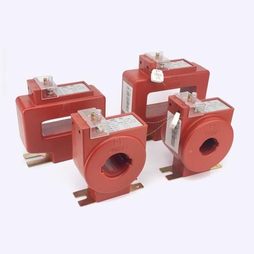
A zero-sequence CT is usually installed around the cable to detect single-line-to-ground faults. This is a standard feature on many cable outgoing feeders because ground faults are among the most common real-world distribution problems.
Ground fault detection quality depends not only on the CT itself, but also on cable routing through the core, shielding arrangement, wiring correctness, and relay logic. I have seen excellent relays made useless by one careless retrofit of secondary wiring.
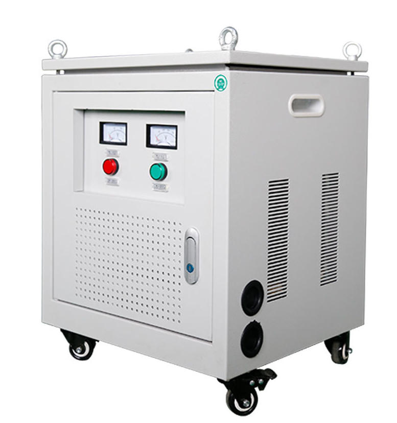
PT Cabinet and Its Four Main Functions
The PT cabinet performs four critical functions:
Voltage measurement
Protection voltage input
220V control power support
Open-delta zero-sequence voltage detection
Without the PT cabinet, the RMU loses much of its system awareness. In practice, a cabinet with no PT support and no battery backup feels electrically alive but operationally half-blind.
Why PT and Backup Power Matter for Automation
Field operators often complain that “the DTU is installed, but automation still fails.” The reason is usually not the DTU itself. It is the loss of auxiliary power, dead battery strings, poor charger health, failed PT-derived supply, or unstable communication devices.
In other words, remote control is only as good as the weakest support circuit. A modern automation-ready RMU with dead DC backup is like a smart phone with a cracked battery and no signal: impressive on paper, unreliable in a storm.
Standard Auxiliary Components
Most RMUs also include the following standard devices:
Surge arrester for lightning and overvoltage protection
Live-line indicator on the door to indicate energized condition
European separable cable connectors for insulated compact cable interfaces
Cable fault monitoring for current and temperature observation
Anti-condensation heaters to limit moisture risk
These are not minor accessories. In humid, coastal, dusty, or poorly ventilated sites, these auxiliary features often determine whether the installation remains dependable after five years.
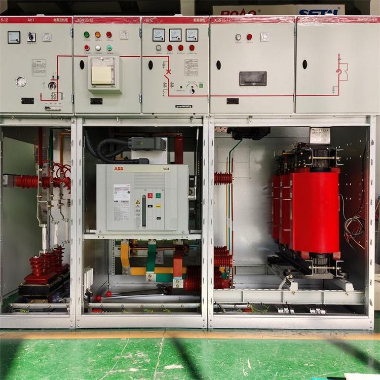
Ring Main Unit and Transformer Connection
The ring main unit transformer connection concept is simple but important. The ring feeders pass through the RMU as incomers, and selected outgoing feeders connect to local transformers that step medium voltage down to low-voltage utilization systems.
In many package substations, the RMU and transformer are physically close, but functionally distinct. The RMU manages medium-voltage switching and network sectionalizing, while the transformer provides local supply conversion to 0.4kV or another utilization level.
When analyzing transformer feeders, check not only the outgoing switch and relay settings, but also the CT/PT arrangement, fault passage indication, cable termination quality, and whether metering responsibility lies on the medium-voltage side or low-voltage side.
Typical 9-Panel RMU Arrangement and Function
| Panel Position | Typical Name | Main Function | Inspection Focus |
|---|---|---|---|
| Side | DTU Cabinet | Remote signaling, control, feeder automation, communication | Power supply, battery, SCADA link, SOE/event records |
| Front 1 | PT Cabinet | Voltage measurement, protection input, control power, zero-sequence voltage | Fuse condition, PT health, control voltage output |
| Front 2 | Incoming Feeder 1 | Source entry from upstream ring section | Switch status, relay logic, cable termination |
| Front 3 | Outgoing Feeder 1 | Load supply | CT ratio, zero-sequence CT, cable sealing |
| Front 4 | Outgoing Feeder 2 | Load supply | Interlock, indicator, heater operation |
| Front 5 | Outgoing Feeder 3 | Load supply | Protection setting, connector temperature |
| Front 6 | Outgoing Feeder 4 | Load supply | Secondary wiring, fault indicator |
| Front 7 | Outgoing Feeder 5 | Load supply | Earthing continuity, cable identification |
| Front 8 | Incoming Feeder 2 | Alternate source entry from other ring side | Open-point logic, synchronism policy, labeling |
Main RMU Components, Purpose, and Inspection Focus
| Component | Purpose | Common Failure Point | What Technicians Should Verify |
|---|---|---|---|
| Gas Tank | Insulation and enclosure of switching parts | Gas leakage or pressure alarm | Pressure indication, sealing integrity, alarm contacts |
| Circuit Breaker / Load Break Switch | Make/break load or fault current depending on design | Mechanism wear, incomplete operation | Operation counter, travel, manual/remote switching |
| Three-Position Switch | Service, isolation, earthing | Interlock defects, wrong position indication | Mechanical locking, position linkage, safe sequence |
| CT | Protection, measurement, metering | Ratio mismatch, secondary circuit issues | Polarity, burden, terminal tightness, ratio records |
| Zero-Sequence CT | Ground fault detection | Incorrect cable passing or wiring errors | Core installation, sensitivity setting, relay pickup |
| PT | Voltage reference and control support | Fuse operation, secondary loss | Voltage output, open-delta wiring, control circuit supply |
| Surge Arrester | Overvoltage protection | Aging after repeated surges | Condition indication, grounding path, installation spacing |
| Live-Line Indicator | Visual energized indication | False confidence from failed indicator | Functional test, never use as sole safety proof |
| Cable Connector | Insulated cable termination | Moisture ingress, poor workmanship, overheating | Torque, sealing, partial discharge signs, thermal scan |
| Heater | Anti-condensation | Heater burnout or thermostat failure | Current draw, thermostat action, cabinet humidity signs |
Normal Operation vs Fault Restoration in an RMU
| Scenario | Switching State | Open Point | Operator Action | Service Impact |
|---|---|---|---|---|
| Normal Operation | Ring physically complete, one designated switch open | Fixed normal open point | Monitor load flow and feeder status | All healthy loads supplied |
| Fault on One Cable Section | Protection detects abnormal current or fault passage | Still open initially at normal point | Identify faulty section boundaries | Part of feeder may lose supply temporarily |
| Fault Isolation | Both ends of faulty section opened | Normal open point unchanged during isolation | Sectionalize damaged cable/feeder | Only faulted section remains out |
| Supply Restoration | Healthy sections reconfigured from alternate source | Original open point may be closed and moved elsewhere | Close transfer path after checks | Most customers restored quickly |
Common RMU Voltage Classes and Typical Applications
| Voltage Class | Typical Applications | Regional Prevalence | Mainstream in Domestic or Overseas Projects |
|---|---|---|---|
| 12kV class (10kV level) | Urban feeders, residential communities, factories, municipal distribution | Very high in many domestic distribution systems | Mainstream domestic |
| 24kV class | Industrial plants, mining, export EPC projects | Moderate to high in selected international markets | Common overseas and specialized industrial |
| 33kV class | Utility distribution, renewables, regional substations | Very high in Africa, Southeast Asia, Middle East | Mainstream overseas |
| 36kV class (35kV level) | Industrial parks, PV, wind power, substation support | High in renewable and industrial applications | Mainstream in selected sectors |
How to Read and Analyze an RMU Like a Technician
If you want to analyze an RMU competently, use this five-step framework:
1. Identify both power sources. Know which feeders are incomers and where they originate.
2. Locate the normal open point. This tells you the intended operational split.
3. Distinguish incomers from outgoers. Do not assume by position alone; verify with diagrams and cable tagging.
4. Check CT and PT functions. Protection and automation are only as trustworthy as their instrument transformers and secondary circuits.
5. Trace the fault isolation path. Ask which two switches isolate a given cable fault and how healthy sections are restored.
When I train junior technicians, I tell them not to start with the nameplate. Start with the one-line diagram, then the cable routes, then the interlocks, then the auxiliary power. The cabinet door may look sophisticated, but the system truth lies in the operating logic.
Common Failure Modes and Field Pain Points
In actual service, RMU failures are rarely mysterious. They tend to follow recurring patterns:
Moisture ingress causing insulation degradation or condensation-related tracking
Mechanism wear leading to stiff operation or incomplete switch travel
Gas pressure issues in sealed compartments
Cable termination faults from poor workmanship or sealing failure
Incomplete interlocks or damaged position linkages
Poor labeling that confuses maintenance and restoration actions
The most underrated pain point is not the switchgear body. It is documentation quality. I have seen excellent equipment become dangerous because feeder tags, schematic revisions, and open-point identification were not updated after one expansion project.
From a standards perspective, asset owners should align inspection and maintenance programs with the intent of IEC 62271 equipment requirements, relevant IEEE practices for switchgear maintenance and system reliability, and local utility operating rules. Standards do not prevent every failure, but they sharply reduce preventable ones.
What Real Practitioners Discuss on Reddit, Quora, and Industry Forums
Across technician forums, Q&A sites, and practitioner communities, the same themes keep appearing. People ask basic definition questions, but the deeper discussions are about restoration practicality, cable termination reliability, and whether remote automation really works when things get ugly.
I reviewed recurring community discussions and compared them with field experience. The patterns are surprisingly consistent: the equipment concept is well understood on paper, but site reality depends on workmanship, auxiliary systems, and operational discipline.
Frequent Field Detail: The “Ring” Is Often Not Fully Closed in Normal Service
A very common discussion topic is the confusion between ring-connected and ring-operated. Many users assume a ring means both sources feed simultaneously in a closed loop during normal service.
Practitioners repeatedly clarify that many networks are physically looped but electrically open at one point. This matters for fault current control, directional protection coordination, and practical utility operation.
Hidden Pain Point: Cable Terminations Cause More Trouble Than the Cabinet
This is one of the most valuable real-world themes. In many user reports, the RMU enclosure itself remains healthy while the real outages come from separable connectors, stress control errors, moisture sealing failures, or poor cable preparation.
I strongly agree with this. In several fault reviews I participated in, the cabinet was initially blamed because it was the visible asset, but thermal imaging, insulation testing, and disassembly showed the root cause at the cable head, not inside the switch tank.
Automation Reality Check: Remote Control Depends on Auxiliary Power Health
Another repeated complaint is that the DTU, RTU, or feeder automation package exists but is unreliable in actual outage events. The reason is almost always upstream of software glamour: PT supply loss, weak batteries, charger failure, communication dropouts, or bad SCADA integration.
This is where glossy sales language and operational reality separate. A remotely operable RMU is only remotely useful if the auxiliary ecosystem survives disturbance.
Safety Lesson from Real Users: Live Indicators Help, but Test-Before-Touch Still Rules
Operators consistently repeat one safety lesson: live-line indicators are helpful, but they are not permission to touch. Isolation, earthing, absence-of-voltage verification, and lockout procedures still rule.
This aligns with every serious safety doctrine in medium-voltage work. A glowing indicator on a door is information, not proof.
Voltage-Class Misconception: Many Users Assume RMU Means Only 10kV
Field discussions also reveal a terminology trap. Many users casually use “RMU” as a synonym for 10kV gas cabinet because that is what they see most often.
But engineers in industrial parks, renewable projects, and overseas utility work regularly discuss 24kV, 33kV, and 36kV RMUs. This is not a niche exception. It is normal practice in many markets.
Real-World Example: Two-Source, Five-Load RMU Fault Scenario
Consider a two-in, five-out arrangement supplied from Source A and Source B. Five downstream loads are connected through five outgoing feeder cabinets.
Under normal conditions, the ring is physically complete, but one designated point is open. Loads 1 to 3 are mainly supplied from Source A, and Loads 4 to 5 from Source B.
Now assume the cable section between the two middle cabinets fails due to an insulation breakdown. A fault indication appears, the affected feeder trips, and operators confirm the faulted segment boundaries.
The two switches on both sides of the failed section are opened to isolate that cable. Then the normal open point is closed after verification, allowing the healthy feeders previously depending on the lost side to be backfed from the alternate source.
Result: the faulty segment remains isolated, but all five downstream loads can often be restored except the section directly tied to the damaged cable. This is the practical reason RMUs are so valuable in urban and industrial distribution.

How RMUs Compare with Other Medium Voltage Switchgear Systems
An RMU is one category within the wider world of medium voltage switchgear systems. It is not the answer to every switching problem, but it excels in a specific niche.
Compared with large metal-clad switchgear: RMUs are more compact but usually less flexible in complex busbar arrangements.
Compared with simple radial cabinets: RMUs offer much better fault isolation and restoration capability.
Compared with open-air or less enclosed arrangements: RMUs improve safety and environmental protection.
Compared with highly customized substation switchgear: RMUs are better for compact distribution nodes, not major transmission switching duties.
In short, if your problem is compact distribution switching with continuity requirements, RMUs are often the right answer. If your problem is high-complexity bus management or large-scale protection zoning, broader switchgear solutions may fit better.
Selection Criteria: How to Choose the Right RMU
Choosing the right RMU means matching equipment to system reality, not buying the most familiar cabinet shape. Key selection factors include:
Voltage level: 12kV, 24kV, 33kV, or 36kV as required
Rated current and expected load growth
Fault level and short-circuit withstand duty
Insulation type: gas-insulated, solid-insulated, or hybrid design
Automation needs: DTU, remote control, communication protocol
Metering accuracy: CT/PT class and commercial metering requirements
Expansion space: future feeders and panel extension possibility
Maintenance strategy: sealed-for-life claims versus actual service access
Ask one hard question during procurement: what is the maintenance truth after five to ten years? Many projects focus on initial compactness and ignore long-term support, spare parts, communication obsolescence, and cable interface serviceability.
Installation and Maintenance Checklist
Use the following practical checklist for installation and periodic inspection:
Foundation: level, vibration-free, with proper room drainage
Cable routing: no crushing, no excessive bend radius, clear identification
Earthing: continuous, low-resistance, correctly bonded
Gas status: pressure or density indication normal
Interlocks: mechanical and electrical interlocks verified
Secondary wiring: correct terminations, labeled, tested
PT/CT verification: ratio, polarity, output, fuse condition
Heater function: thermostat and anti-condensation function confirmed
Communication: DTU/SCADA points checked end-to-end
Inspection interval: aligned with manufacturer recommendation, IEC practice, and site environment
Where possible, combine periodic visual inspection with thermal imaging, insulation testing, event log review, and a disciplined labeling audit. A surprising number of outages become hard to restore only because panel and feeder identification were allowed to drift over time.
FAQ
What is a ring main unit in simple terms?
A ring main unit is a compact medium-voltage switching cabinet that connects, protects, and controls feeders in a ring-type distribution network so power can be supplied more reliably from more than one direction.
How does an RMU improve power supply reliability?
It improves reliability by allowing operators to isolate only the faulted cable or feeder section while restoring healthy sections from an alternate supply path through the ring. This reduces the outage area compared with a single radial feeder.
Is a ring main unit only for 10kV systems?
No. The 10kV/12kV class is the most common in many domestic systems, but RMUs are also widely used at 24kV, 33kV, and 35kV/36kV depending on industry, project type, and region.
Is there such a thing as a low-voltage RMU at 0.4kV?
Normally no. At 0.4kV, the correct terms are low-voltage distribution cabinet, switchboard, power cabinet, or motor control center, not RMU.
Is a ring main unit normally operated in a closed loop?
Usually, the network is physically ring-connected but operated open at one designated point during normal conditions. This keeps operational flexibility while avoiding full parallel closure.
What is the difference between an RMU and general switchgear?
An RMU is a specialized form of medium-voltage switchgear focused on compact ring-feeder distribution, fast fault isolation, and local automation. General switchgear is a broader category that includes many other designs for substations, industrial plants, and busbar systems.
What is inside a gas-insulated ring main unit?
It typically contains sealed switching components such as load-break switches or circuit breakers, a gas tank, cable interfaces, instrument transformers, position indicators, interlocks, and auxiliary circuits for control and monitoring.
How is a ring main unit connected to a transformer?
The RMU receives incoming ring feeders and uses one or more outgoing feeder ways to supply local transformers. The transformer then steps the medium voltage down to the utilization voltage for building or process loads.
What is the purpose of the PT cabinet in an RMU?
The PT cabinet provides voltage measurement, protection reference signals, control power support such as a 220V supply, and open-delta zero-sequence voltage detection for fault-related functions.
What does the three-position switch do in an RMU?
It provides three controlled states: service, isolation, and earthing. This helps combine compactness with safer maintenance procedures and reduces the chance of incorrect switching sequences.
What faults can an RMU detect?
Depending on its configuration, an RMU can detect feeder overcurrent, earth faults, single-line-to-ground faults, cable abnormalities, voltage loss, and other protection or alarm events through relays, CTs, PTs, and automation devices.
What should be checked during RMU maintenance?
Key checks include gas pressure or density status, switch mechanism condition, interlocks, insulation condition, CT/PT health, cable terminations, heater operation, communication status, battery or control power condition, and earthing continuity.
The Fastest Way to Understand and Judge an RMU
If you understand five things, you can judge most RMU installations with confidence: the cabinet lineup, how the ring is formed, where the normal open point is, what the key components do, and which voltage class the project actually uses.
Once these are clear, the RMU stops being a mysterious box and becomes a logical system. You can analyze incomers and outgoers, evaluate ring main unit transformer connection schemes, check whether the gas-insulated ring main unit is suitable for the site, and understand how fault restoration should work in the real network.
That is the real learning threshold. When you can look at a lineup and immediately identify source paths, PT support, CT roles, earthing logic, cable risk points, and transfer possibilities, you have moved from recognition to engineering judgment.
Evaluate Your Distribution Network Before the Next Fault
Do not wait for the next outage to discover weak points in your RMU in power distribution. Review your current medium voltage switchgear system, map your actual ring topology, confirm the normal open point, verify PT and DTU readiness, check whether your selected voltage class is correct, and inspect cable terminations with the same seriousness you give the cabinet itself.
If you are planning a new installation or upgrade, consult a qualified engineer or supplier and demand evidence of compliance with relevant IEC and IEEE practices, realistic maintenance support, and field-proven automation reliability. A well-selected RMU does not just save space. It protects continuity, safety, and operational credibility when the fault finally comes.