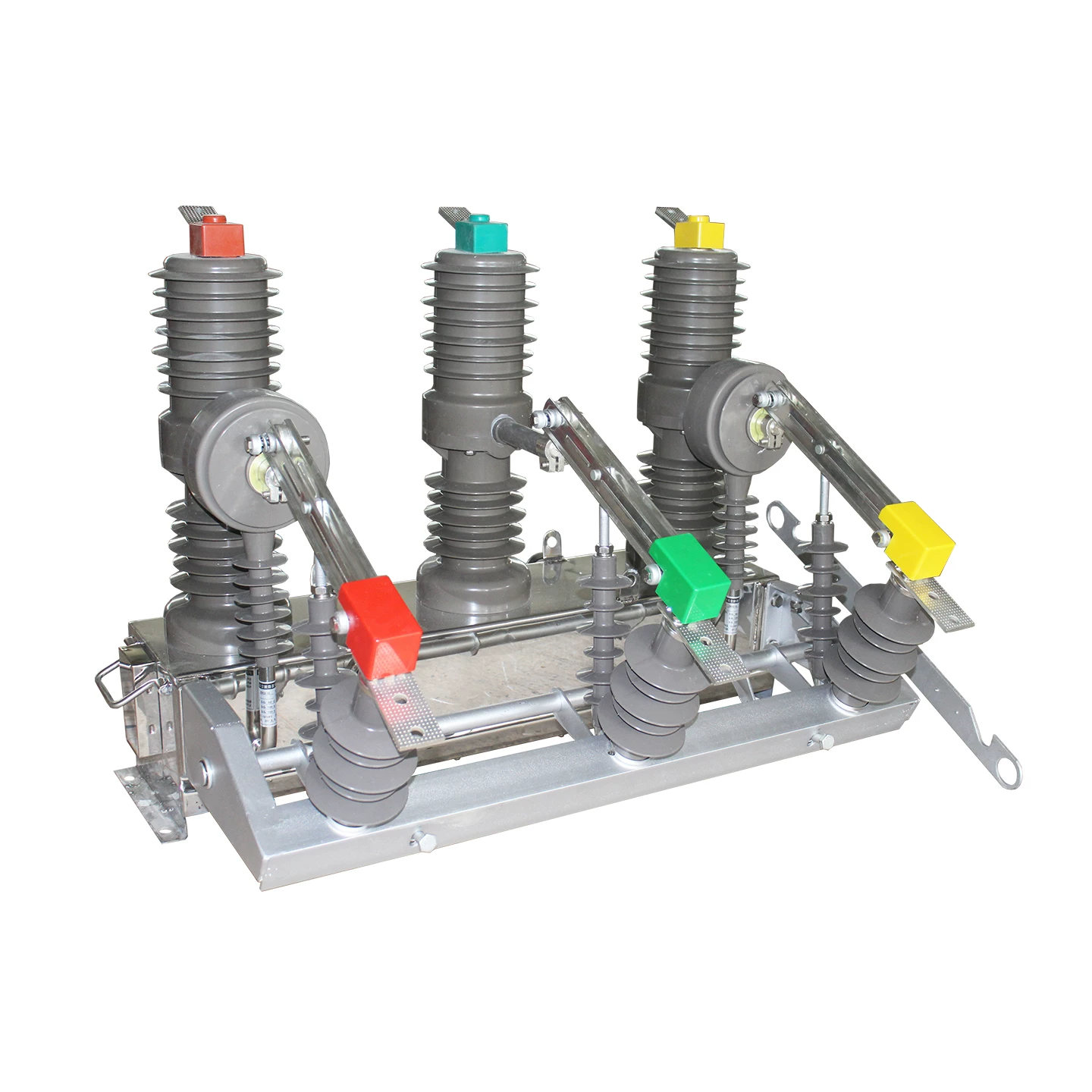
"surge arrester" and "lightning arrester" are not synonyms. Under modern IEC 60099-4 and IEEE C62.11 practice, surge arrester is the umbrella term for gapless metal-oxide devices that clamp transient overvoltages of any origin — lightning, switching, or temporary. Lightning arrester is the legacy label for gapped silicon carbide devices built specifically for lightning transients on overhead lines. Every lightning arrester is a subset of surge arresters, but not every surge arrester is optimized for the energy signature of a direct lightning stroke.
That distinction is not academic. Terminology drift across bid documents, single-line diagrams, and maintenance procedures routinely causes engineers to specify or install the wrong device class — an error that surfaces later as transformer failures, cascading outages, and coordination violations against equipment BIL. Across utility and industrial sectors, transient-related equipment losses conservatively account for billions in unplanned outages annually, and a meaningful share of them traces back to the comfortable assumption that "the two terms are used interchangeably."
This guide is written for design engineers, protection specialists, and asset managers who need to close that ambiguity gap. It resolves the terminology, dissects the physics, maps devices to protection zones, and provides a defensible selection framework grounded in IEC and IEEE standards.
Terminology Clarified — Why "Surge Arrester" and "Lightning Arrester" Are Not Synonyms
Before comparing hardware, the vocabulary itself must be pinned down. The two terms occupy overlapping but non-identical technical territory, and modern standards have deliberately moved toward one preferred label.
The Historical Evolution of the Terminology
The phrase "lightning arrester" originated in the early 20th century, when the dominant technology was the gapped silicon carbide (SiC) block. These devices were built specifically to divert lightning-induced surges on overhead lines, and the name reflected that narrow purpose.
The 1970s and 1980s brought a step change: the introduction of gapless metal-oxide varistor (MOV) technology based on zinc oxide ceramics. MOV devices could suppress not just lightning transients but also switching surges and temporary overvoltages — a much broader mission that demanded a broader name.
Modern standards — IEC 60099-4 and IEEE C62.11 — accordingly adopted "surge arrester" as the umbrella term. Regional linguistic drift persists, however. North American utilities still occasionally reference "lightning arresters" in legacy drawings; European and Asia-Pacific procurement documents have largely migrated to "surge arrester." Field engineers must read both dialects fluently.
The Functional Definition Difference
The clean functional split is straightforward once stated plainly.
Lightning arrester (traditional sense): A device designed primarily to divert direct or induced lightning transients on overhead conductors to ground.
Surge arrester (modern sense): A device designed to limit transient overvoltages of any origin — lightning electromagnetic pulses (LEMP), switching electromagnetic pulses (SEMP), or temporary overvoltages (TOV).
The overlap zone is instructive: every lightning arrester performs a subset of surge arrester duties, but not every surge arrester is optimized for the energy signature of a direct lightning stroke. This is where the surge protection device vs lightning arrester debate becomes an engineering decision, not a semantic one.
Standards Governing Each Term
| Standard | Scope | Preferred Term |
|---|---|---|
| IEC 60099-4 | Metal-oxide arresters without gaps for AC systems | Surge arrester |
| IEEE C62.11 | Metal-oxide surge arresters for AC power circuits (>1 kV) | Surge arrester |
| IEC 61643-11 | Low-voltage surge protective devices | SPD |
| IEC 62305 | Lightning protection systems (external and internal) | Lightning protection / LPS |
| IEC 60099-8 | Externally gapped line arresters (EGLA) for overhead lines | Line arrester |
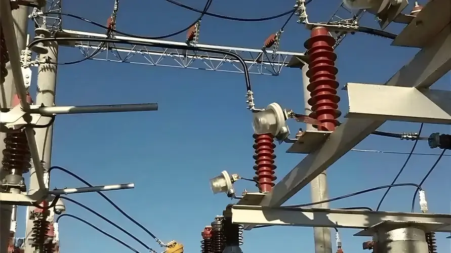
Working Principles — Inside the Physics of Overvoltage Diversion
The two device families operate on fundamentally different material physics. Understanding those differences explains almost every downstream performance gap.
How a Traditional Lightning Arrester Works (Gapped SiC Design)
A gapped SiC arrester sits electrically dormant under normal system voltage. When an incoming surge exceeds the spark gap's breakdown threshold, the air gap ionizes and conducts the transient current through a stack of silicon carbide valve blocks to ground.
SiC provides a nonlinear resistance that limits — but does not clamp aggressively — the residual voltage. Once the surge passes, the gap must interrupt the power-frequency follow current, a duty that depends on gap geometry and system fault levels. Limitations are well documented: slower response, higher residual voltage, gradual degradation with each operation, and — in older porcelain designs — a genuine risk of explosive failure.
How a Modern MOV Surge Arrester Works
The zinc oxide (ZnO) MOV disc is a doped polycrystalline ceramic. Each grain boundary behaves as a microscopic back-to-back diode junction with a well-defined breakdown voltage. Under nominal service voltage, only microampere-range leakage current flows. When a transient drives the voltage past the boundary threshold, conduction becomes massively nonlinear.
Sub-nanosecond intrinsic response, with practical clamping under 25 ns
Nonlinear V-I coefficient (α) typically 30–50, versus 5–7 for SiC
Energy absorption ratings commonly 4–15 kJ/kV of rated voltage
Negligible follow current — the disc reverts to its high-impedance state as voltage recovers
The MOV Surge Arrester Function in Detail
Three engineering realities shape MOV design. First, the grain-boundary breakdown voltage sets the clamping level and is temperature-sensitive, which is why MCOV must be specified conservatively. Second, sustained energy dissipation can drive the disc into thermal runaway if the heat generated by leakage current exceeds heat rejected to the housing — hence the criticality of pressure-relief and disconnector design.
Third, MOVs age. Leakage current drifts upward over decades due to grain-boundary diffusion, and moisture ingress through compromised seals accelerates the process. Modern polymer-housed units mitigate both mechanisms through hermetic silicone rubber overmolding directly onto the MOV column.
Response Time and Voltage Clamping Comparison
| Parameter | Gapped SiC Lightning Arrester | Modern MOV Surge Arrester |
|---|---|---|
| Response time | 1–5 μs | <25 ns |
| Residual voltage (10 kA, 8/20 μs) | ~3.5 × Ur | ~2.3 × Ur |
| Follow current | Present, requires interruption | Negligible |
| Nonlinearity coefficient α | 5–7 | 30–50 |
| Service life | 15–20 years | 25–30 years |
| Failure mode | Explosive (older designs) | Controlled pressure relief |
Physical Construction and Component Anatomy
Internal build quality determines field reliability at least as much as electrical rating. The mechanical divergence between legacy and modern arresters is significant.
Lightning Arrester Construction (Legacy and Line-Type)
Traditional units are built inside porcelain housings sealed at each end with metal fittings and organic gaskets. Internally, series spark gaps alternate with SiC valve blocks stacked axially. Grading rings equalize voltage distribution along the stack, and a pressure-relief vent — typically a diaphragm — provides a controlled failure path.
Line-type expulsion arresters, still deployed on some rural distribution systems, use a different principle: the surge current ionizes an arc-quenching tube (often boric acid or gas-filled), and the escaping gas extinguishes the follow-current arc through blast action.

Surge Arrester Construction (Modern Station, Distribution, and DC Classes)
Contemporary MOV arresters are built in one of two mechanical philosophies. In the wrapped design, the MOV column is wound with fiberglass-reinforced composite and overmolded with silicone rubber sheds. In the cage design, MOVs are held between end fittings by external composite rods, with the silicone housing applied over the assembly.
Polymer housings tolerate seismic events and vandalism far better than porcelain
Silicone hydrophobicity maintains creepage performance in polluted or coastal environments
Distribution-class units integrate a ground-lead disconnector that isolates a failed arrester from the network
Grading capacitors are used on tall EHV stacks to linearize voltage distribution
Class Categorization Under IEC 60099-4
| Arrester Class | Nominal Discharge Current | Typical Application |
|---|---|---|
| Station Class (SH, SM, SL) | 10–20 kA | HV/EHV substations, transformer protection |
| Distribution Class (DH, DM, DL) | 5–10 kA | 11–33 kV feeders and pole-mount transformers |
| Line Discharge Class 1–5 | Graded by energy handling | Transmission lines and shunt reactors |
| Low-voltage SPD (Type 1/2/3) | 12.5–100 kA (10/350 or 8/20) | Buildings, panels, terminal equipment |
| DC arrester | Application-specific | HVDC converter stations, PV plants |
Application Zones — Where Each Device Belongs in the Protection Hierarchy
The IEC 62305 lightning protection zone (LPZ) concept remains the cleanest framework for placing devices in an installation. Each LPZ boundary imposes a specific overvoltage protection equipment requirement.
External Protection: Where "Lightning Arrester" Terminology Still Applies
The external lightning protection system (LPS) consists of air terminals, down conductors, and an earth termination network. Its job is interception — providing a preferred termination point for the strike so that the discharge current bypasses the structure.
Design is governed by the rolling sphere method, protection angle calculation, or mesh method depending on structure geometry. In this context — the physical rod on the roof — the "lightning arrester" or "lightning rod" terminology is technically accurate and universally understood.
Internal Protection: The Domain of the Surge Arrester / SPD
Inside the LPZ hierarchy, coordinated cascade protection drives the design.
LPZ 0/1 boundary: Type 1 SPD (low-voltage) or station-class surge arrester (medium/high voltage)
LPZ 1/2 boundary: Type 2 SPD at sub-distribution panels
LPZ 2/3 boundary: Type 3 SPD at sensitive equipment terminals
Each stage progressively reduces the let-through voltage. Skipping stages, or placing an under-rated device at an outer boundary, is a leading root cause of equipment damage even when the "protection" nameplate is present.
Lightning Rod vs Surge Arrester — A Frequently Confused Pair
The lightning rod vs surge arrester distinction is the most common conceptual error in facility protection design. The two devices do not substitute for one another.
A lightning rod intercepts the strike and controls where the discharge current enters the earthing system. It does nothing about the resulting conducted and induced transients propagating along power, data, and signal cables. A surge arrester (or SPD) has no interception role; it clamps those conducted transients at the boundary of protected equipment. IEC 62305 requires both for a complete protection scheme against direct strikes.
Transient Voltage Suppression Across Voltage Levels
| System Voltage | Primary Device | Typical Location |
|---|---|---|
| ≤1 kV LV | SPD Type 1/2/3 | Main panel, sub-panel, socket outlet |
| 11–36 kV MV | Distribution surge arrester | Pole-top, transformer terminals |
| 66–245 kV HV | Station-class surge arrester | Substation bus, transformer bushings |
| 400–800 kV EHV | Line discharge class 4–5 | Line entrances, shunt reactors |
| HVDC | DC surge arrester | Converter station, DC bus, valve hall |

Selection Criteria — An Engineering Decision Framework
Correct selection is a six-parameter problem aligned with IEC 60099-5 application guidelines. Skipping any parameter creates a protection gap or a premature failure risk.
The Six Parameters Every Specifier Must Define
1. Continuous operating voltage (Uc / MCOV): The highest RMS voltage the arrester tolerates indefinitely without thermal instability
2. Rated voltage (Ur): The voltage on which TOV capability and duty tests are referenced
3. Nominal discharge current (In): The 8/20 μs current at which residual voltage is characterized
4. Line discharge class or energy absorption capability: Governs long-duration switching-surge duty
5. Temporary overvoltage (TOV) capability: Must exceed expected fault-condition overvoltages
6. Pressure relief / short-circuit withstand: Must exceed the maximum available fault current at the installation point
Insulation Coordination and Protective Margin
The arrester's protective level must sit safely below the basic insulation level (BIL) or lightning impulse withstand level (LIWL) of the protected equipment. Industry practice targets a protective ratio of at least 1.2, calculated as BIL divided by arrester residual voltage at the coordination current.
Separation distance matters too. Every meter of conductor between the arrester and the protected apparatus adds inductive voltage rise during a fast-front surge, typically 1 kV per meter for a 10 kA/μs current gradient. Tight coupling to the transformer bushing is not a cosmetic preference — it is a coordination requirement.
Environmental and Mechanical Considerations
Pollution class (IEC 60815): Determines minimum creepage distance from 16 mm/kV (very light) to 53.7 mm/kV (very heavy)
Seismic zone: High seismic areas favor polymer housings and cantilever-rated end fittings
Altitude derating: Above 1,000 m, external insulation must be derated per IEC 60071-2
Coastal and industrial atmospheres: Silicone polymer outperforms porcelain for hydrophobicity recovery and salt-fog endurance
Real-World Case Studies and Field Data
Case Study 1 — Wind Farm Collector Substation
A 200 MW onshore wind farm operating on a 34.5 kV collector network experienced repeated transformer failures during switching operations. Root cause analysis, published in an IEEE PES technical paper, identified that the legacy gapped SiC units originally installed could not handle the high-frequency multiple-restrike transients characteristic of vacuum breaker operations on inductive loads.
After retrofit to polymer MOV surge arresters with Class 3 energy rating and tightly coordinated MCOV, the transformer failure rate on the affected feeders dropped by roughly 76% over the following 24 months of monitoring.
Case Study 2 — Data Center Multi-Level SPD Coordination
A hyperscale data center operator instrumented one of its facilities to measure let-through voltages under simulated lightning current injection. A single-stage "lightning arrester" approach at the service entrance produced peak transients of approximately 2.4 kV at the server rack PDU. Introducing a cascaded Type 1 + Type 2 + Type 3 architecture reduced measured rack-level let-through to under 600 V — well within ITE equipment tolerance.
The retrofit cost was recovered in under 14 months through avoided PSU replacements and reduced unplanned reboots.
Case Study 3 — HV Transmission Line Retrofit
A 132 kV overhead transmission corridor in a keraunic-dense region documented an average of 4.8 lightning-induced outages per 100 km per year. Installation of externally gapped line arresters (EGLA) per IEC 60099-8 on the top phases reduced the outage rate to 0.9 per 100 km per year over three subsequent monitoring seasons.
Industry Reliability Data Snapshot
| Equipment Type | Typical MTBF | Common Failure Cause |
|---|---|---|
| Legacy SiC lightning arrester | 15–20 years | Moisture ingress, gap deterioration |
| Polymer MOV surge arrester | 25–30 years | End-of-life MOV aging |
| Porcelain MOV surge arrester | 30+ years | Housing damage, seal failure |
| Low-voltage SPD Type 2 | 5–10 years | Repeated surge exhaustion |
| EGLA on transmission lines | 20–25 years | Series gap degradation, mechanical fatigue |
Testing, Maintenance, and Condition Monitoring
Specification without lifecycle management is incomplete engineering. A well-selected arrester still requires structured testing at manufacture and periodic condition assessment in service.
Factory and Type Tests Per IEC 60099-4
Residual voltage test: Characterizes clamping at steep-front, lightning, and switching impulse currents
Operating duty test: Simulates repeated surge exposure combined with power-frequency voltage
Accelerated aging test: Verifies long-term stability at elevated temperature and voltage
Short-circuit / pressure-relief test: Confirms safe failure behavior at maximum system fault current
Field Monitoring Techniques
Modern asset management programs move beyond time-based replacement toward condition-based intervention. Four techniques dominate practice.
Leakage current monitoring: The resistive component (Ir) is the diagnostic value, not total leakage. A rising Ir trend signals MOV aging
Surge counters and event recorders: Track cumulative operations and correlate with lightning flash density data
Thermographic inspection: Hot spots during peak load indicate elevated resistive losses in a specific unit
Insulation resistance and power factor testing: Baseline against factory acceptance values
End-of-Life Indicators and Replacement Criteria
Three signals justify proactive replacement independent of chronological age: resistive leakage current exceeding manufacturer thresholds (commonly a doubling from baseline), visible housing degradation or persistent corona activity, and cumulative energy absorption approaching rated capability based on recorded events. Any two of the three in combination warrants immediate replacement planning.

Common Misconceptions in Procurement and Design Documents
"Any Arrester Will Do" — Why Class Matters
Substituting a distribution-class unit for a station-class specification is not a cost optimization — it is a coordination violation. Distribution units have lower energy absorption, coarser residual voltage tolerance, and different TOV curves. On a system with resonant-grounded or ungrounded neutrals, an under-specified TOV rating drives the unit into thermal runaway during single-phase faults.
"Lightning Arrester" on Modern Substation Drawings
The label sometimes reflects legacy nomenclature carried forward from decades-old drawing templates. In other cases it reflects an actual specification error where a procurement engineer copied a distribution-line term into a station application. The recommended engineering practice is to migrate all new drawings to "surge arrester" and to annotate the specific IEC 60099-4 class designation directly on the symbol.
SPD vs. Surge Arrester in Low-Voltage Systems
Low-voltage distribution boards need SPDs per IEC 61643-11, not MV surge arresters. The two device families are separated by voltage domain, discharge waveform (10/350 μs versus 8/20 μs), and mechanical form factor. Mixing them in a specification signals that the designer has not internalized the standards structure.
Frequently Asked Questions (FAQ)
Is a lightning arrester the same as a surge arrester?
Not exactly. "Lightning arrester" historically referred to gapped silicon carbide devices built specifically for lightning transients on overhead lines. "Surge arrester" is the modern umbrella term used by IEC 60099-4 and IEEE C62.11, covering gapless metal-oxide devices that clamp lightning, switching, and temporary overvoltages. Every lightning arrester is a form of surge arrester, but the reverse is not always true.
Can a surge arrester protect against a direct lightning strike?
A surge arrester handles the conducted transient that follows a strike, but it is not designed to be the primary interception point for a direct stroke on a structure. Direct-strike protection requires an external lightning protection system — air terminals, down conductors, and an earth termination network — per IEC 62305. The surge arrester then limits the resulting overvoltage on power and signal conductors entering the protected zone.
What is the difference between a surge protection device (SPD) and a surge arrester?
The terms occupy different voltage domains and standards. SPDs are governed by IEC 61643-11 and are used in low-voltage systems below 1 kV, categorized as Type 1, 2, or 3 depending on their position in the cascaded protection scheme. Surge arresters are governed by IEC 60099-4 and are used above 1 kV in distribution, transmission, and substation applications. The underlying MOV technology is similar, but ratings, testing, and form factor differ substantially.
How often should surge arresters be replaced?
Replacement is condition-based, not calendar-based, for well-designed installations. Polymer MOV units typically deliver 25–30 years of service life, and porcelain MOV units can exceed 30 years. Trigger replacement when resistive leakage current exceeds manufacturer thresholds, when surge counters indicate cumulative energy near the rated limit, or when visual inspection reveals housing damage or corona traces.
What happens when a surge arrester fails?
A well-designed modern arrester fails safely. Internal pressure from the fault arc vents through pre-engineered relief paths — either diaphragm vents in porcelain designs or the composite housing rupture pattern in polymer designs. Distribution-class units include a ground-lead disconnector that physically separates the failed unit from the network, providing visual indication and allowing the feeder to remain in service until scheduled replacement.
Do I need both a lightning rod and a surge arrester?
Yes, for structures with direct-strike exposure. The two devices address different aspects of the same event. The lightning rod intercepts the strike and controls the discharge path to earth; the surge arrester limits the induced and conducted voltage transients on internal power and signal conductors. IEC 62305 codifies this as complementary external and internal protection.
What is MCOV and why is it critical?
MCOV (Maximum Continuous Operating Voltage), designated Uc in IEC terminology, is the highest RMS power-frequency voltage the arrester can withstand indefinitely without thermal instability. It must exceed the actual continuous voltage stress at the installation point, which on ungrounded or resonant-grounded systems can be line-to-line during single-phase faults. An MCOV set too low guarantees eventual thermal runaway; set too high, the residual voltage during a surge event may exceed the protected equipment's BIL.

Key Takeaways for Engineers and Specifiers
The modern industry term is surge arrester; "lightning arrester" refers either to a legacy gapped SiC subset or to the external interception system (rods and conductors)
MOV technology has replaced gapped SiC in nearly all new medium- and high-voltage installations
Selection is governed by Uc, Ur, In, TOV capability, energy class, and pollution level — never by generic naming on a drawing
Complete lightning protection requires both an external LPS and internal surge arresters or SPDs at LPZ boundaries
Coordinated cascade design across LPZ 0/1, 1/2, and 2/3 boundaries delivers the lowest let-through voltage at sensitive equipment
Condition-based monitoring using resistive leakage current and surge counters outperforms fixed-interval replacement
Take Action on Your Protection Strategy
Terminology precision is not academic — it is the foundation of insulation coordination, procurement accuracy, and operational reliability. If your organization has not audited its protection specifications recently, three concrete steps deliver disproportionate value.
Audit existing substation and facility drawings for terminology and class specification accuracy. Flag every legacy "lightning arrester" callout for engineering review against the current IEC 60099-4 class designation.
Request a coordinated insulation study review from a qualified protection engineer. Validate BIL margins, separation distances, and TOV capability against your actual system grounding and fault levels.
Download the companion selection worksheet aligned with IEC 60099-5 application guidelines, and subscribe for further deep-dive technical guides on protection coordination, HVDC arrester design, and renewable plant transient studies.
Rebuilding a substation after a transient-related transformer failure takes months. The specification review that would have prevented the failure takes hours. Choose the hours.