A 220 kV substation cannot be measured directly by ordinary meters or relays. The voltage is simply too high, too dangerous, and far beyond the input limits of standard control and protection devices.
That is exactly why substations use potential transformers. These instrument transformers reduce high system voltage to a safe, proportional, and standardized value that meters, relays, and automation systems can actually use.
Why a 220 kV Substation Cannot Be Measured Directly
High-voltage substations operate at levels such as 33 kV, 66 kV, 132 kV, 220 kV, and above. Directly connecting measuring instruments to these voltages would create severe insulation, safety, and equipment damage risks.
Even if direct measurement were attempted, conventional meters and protection relays are not designed to accept transmission voltage at their terminals. They require a much lower and standardized input.
This is the core reason a potential transformer in electrical substation practice is indispensable. It makes high voltage measurable without exposing personnel or equipment to the actual line voltage.
The Core Problem: Why Voltage Must Be Stepped Down in a Substation
Substation voltage must be stepped down for safety, accuracy, and practical system operation. High voltage cannot be fed directly into metering panels, relay terminals, or SCADA input cards.
Protection equipment also depends on stable, predictable secondary values. Without voltage transformation, relay coordination, event recording, synchronization, and billing-grade metering would be unreliable or impossible.
Safety: isolates personnel and low-voltage equipment from dangerous primary voltage
Standardization: supplies relay and meter inputs at common secondary levels
Accuracy: allows precise voltage measurement under defined burden and accuracy class
Protection: enables undervoltage, overvoltage, distance, directional, and synchronizing functions
What Is a Potential Transformer in an Electrical Substation?
A potential transformer, also called a voltage transformer, is an instrument transformer used in substations to step down high primary voltage to a low, proportional secondary voltage.
Its main purpose is to provide an accurate voltage signal for measurement, protection, monitoring, and control. In simple terms, it lets engineers and devices “see” a high-voltage system safely.
In a typical potential transformer in an electrical substation installation, the primary side is connected to the high-voltage network, while the secondary side supplies standardized values such as 110 V or 63.5 V.

Potential Transformer Working Principle
The PT transformer working principle is based on electromagnetic induction. When AC voltage is applied to the primary winding, it creates alternating magnetic flux in the magnetic core.
That flux induces a proportional voltage in the secondary winding. Because the number of turns in the secondary is much lower than the effective primary ratio arrangement, the output voltage becomes a reduced but accurately scaled version of the system voltage.
As long as the transformer operates within its rated burden and accuracy class, the secondary voltage remains closely proportional to the primary voltage. This is essential for precision metering and dependable relay operation.
Voltage Transformer Function in Substation
The voltage transformer function in substation systems goes far beyond simple voltage indication. It is a central source of voltage information for nearly every intelligent electrical function.
Metering: supports voltmeters, energy meters, power meters, and transducers
Protection relays: feeds overvoltage, undervoltage, distance, directional, and frequency relays
Synchronization: helps compare bus and incoming line voltage before breaker closing
Indication: provides voltage presence signals for operators and annunciation systems
Control and automation: supplies SCADA, RTUs, disturbance recorders, and bay controllers
In modern substations, PTs are part of the information backbone. Without them, digital protection and automation systems would not receive the voltage reference they need.
Main Components of a Potential Transformer
A potential transformer contains several essential parts that ensure accurate and insulated operation in substation environments.
Primary winding: connected to the high-voltage system
Secondary winding: supplies reduced voltage to meters and relays
Magnetic core: provides the flux path for electromagnetic induction
Insulation system: separates high-voltage and low-voltage sections safely
Terminals: provide primary and secondary connection points
Grounding arrangement: ensures safe reference and fault protection on the secondary side
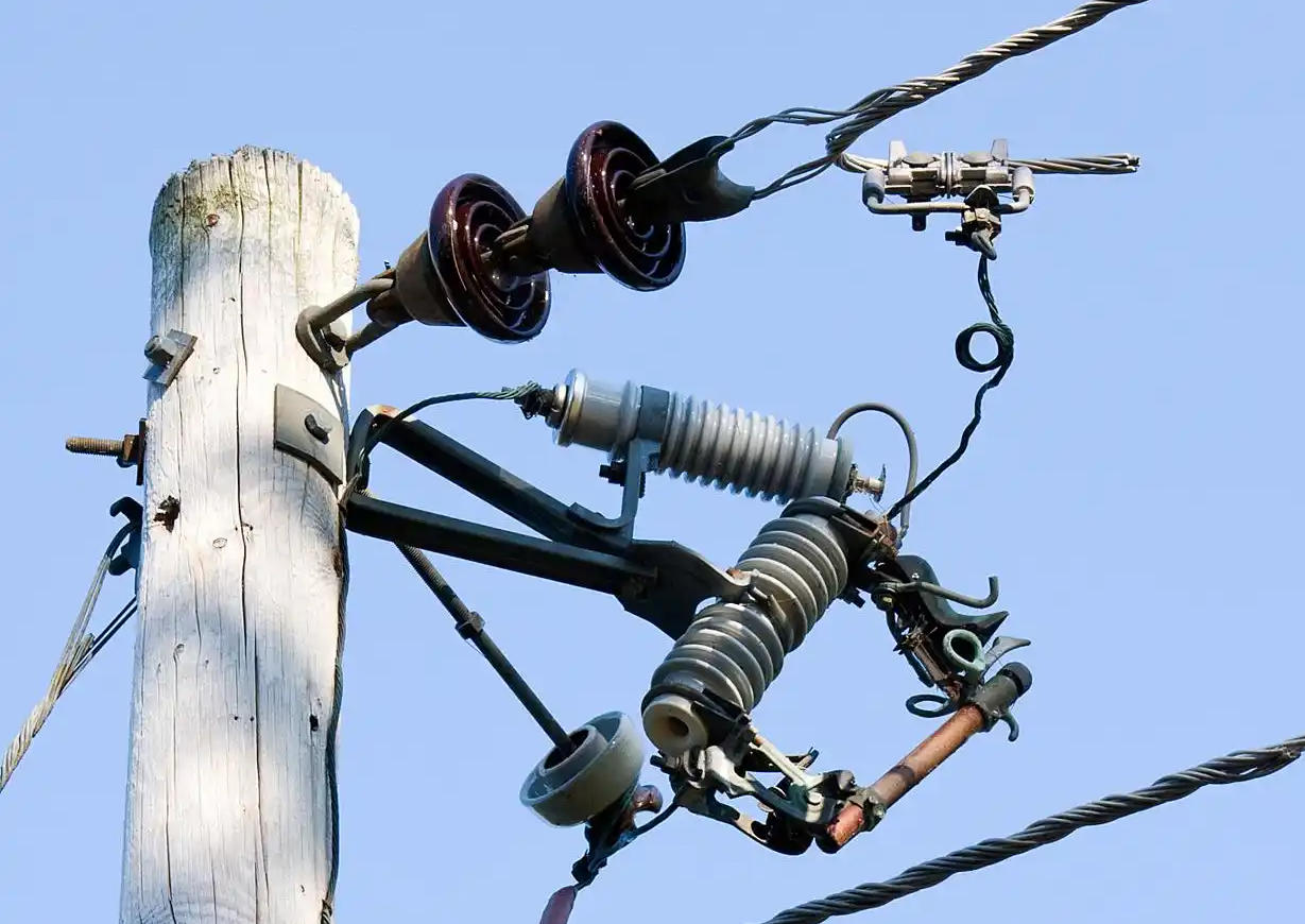
In outdoor high-voltage applications, additional construction features may include porcelain or composite housings, oil or gas insulation, and weather-resistant terminal boxes.
How a Potential Transformer Works in a Substation Step by Step
1. The PT primary is connected to the busbar, feeder, or line voltage to be monitored.
2. The primary voltage produces magnetic flux in the transformer core.
3. The changing flux induces a reduced AC voltage in the secondary winding.
4. The secondary voltage is delivered to connected devices such as meters, relays, and SCADA inputs.
5. Protection and control systems use that scaled voltage to measure, compare, alarm, and trip when necessary.
This process happens continuously and in real time. It allows the substation to monitor system conditions without exposing low-voltage equipment to dangerous primary voltage.
Standard Output Voltage of Potential Transformers
If you ask what is a standard output voltage of potential transformers, the most common answer is that PT secondary voltages are standardized to practical values such as 110 V, 63.5 V, and in some systems 100 V or 115 V.
The exact value depends on regional standards, system grounding method, relay design, and intended application. In three-phase systems, 63.5 V is often used where the phase-to-neutral value corresponds to a 110 V line-to-line secondary.
Utilities choose standardized secondary voltages so protection panels, energy meters, and automation devices can be designed around known inputs. That improves compatibility and reduces engineering complexity.
Table: Common Potential Transformer Ratios and Standard Secondary Voltages
| Primary System Voltage | Typical PT Ratio | Common Secondary Voltage | Application Purpose |
|---|---|---|---|
| 11 kV | 11000 / 110 | 110 V | Metering, protection, indication |
| 33 kV | 33000 / 110 | 110 V | Feeder protection and billing metering |
| 66 kV | 66000 / 110 | 110 V | Bus voltage measurement and relay input |
| 132 kV | 132000 / 110 | 110 V | Transmission metering, distance protection, SCADA |
| 220 kV | 220000 / 110 | 110 V | High-voltage protection and synchronizing |
| Three-phase secondary reference | System dependent | 63.5 V phase-to-neutral | Relay and metering circuits in grounded systems |

Potential Transformer Applications in Power System
The potential transformer applications in power system operation are extensive. PTs are used wherever system voltage must be monitored, recorded, or used for protection logic.
Energy metering: revenue and operational metering in substations and switchyards
Protective relaying: distance, directional, undervoltage, overvoltage, and frequency functions
Fault detection: identifies abnormal voltage conditions during system disturbances
SCADA and automation: feeds remote monitoring and control systems
Synchronizing panels: compares phase angle and magnitude before connecting sources
Power quality analysis: supplies voltage signals to analyzers and disturbance recorders
In real utility practice, PTs are found in transmission substations, distribution substations, generator switchyards, industrial substations, and renewable energy interconnection points.
Types of Potential Transformer Used in Substations
Several PT types are used depending on voltage level, installation environment, and application purpose.
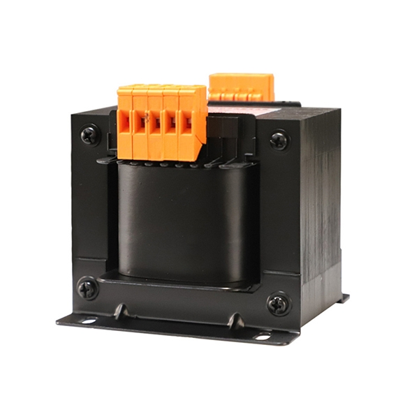
Electromagnetic PT: conventional magnetic-core voltage transformer used widely at medium and high voltage levels
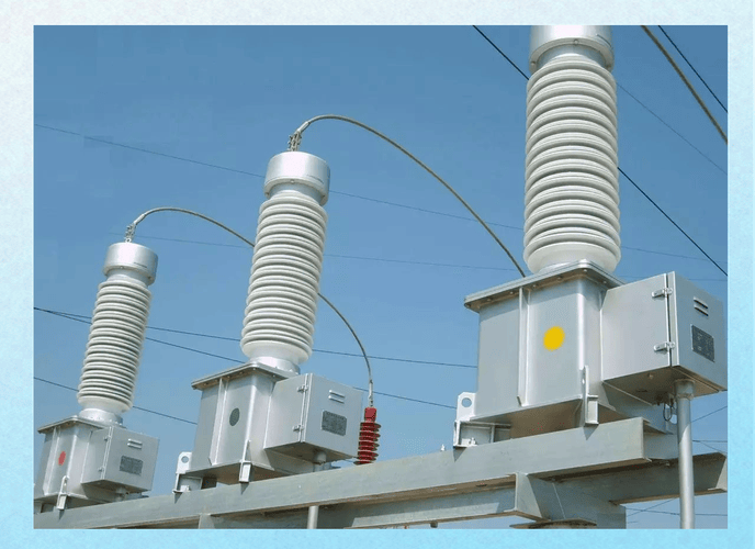
Capacitor Voltage Transformer (CVT): common at higher transmission voltages, especially for protection, metering, and carrier communication coupling functions
Indoor PT: used in metal-clad switchgear and indoor substations
Outdoor PT: designed for open switchyards with weatherproof insulation systems
For EHV applications, CVTs are often chosen because they are economically attractive at high voltages compared with fully electromagnetic designs.
Table: Types of Potential Transformers and Their Typical Substation Uses
| PT Type | Typical Voltage Range | Installation Area | Most Common Use Case |
|---|---|---|---|
| Electromagnetic PT | Low to high voltage | Indoor and outdoor | Accurate metering and protection voltage supply |
| Capacitor Voltage Transformer (CVT) | High to extra-high voltage | Outdoor switchyard | Transmission line protection, metering, and PLCC-related use |
| Indoor PT | Typically medium voltage | Switchgear rooms and panels | Distribution switchgear voltage sensing |
| Outdoor PT | Medium to extra-high voltage | Open substations | Busbar and line voltage measurement in substations |
Potential Transformer vs Current Transformer
The difference between a current transformer and a potential transformer is fundamental. A current transformer measures and scales current, while a potential transformer measures and scales voltage.
They also connect differently in the primary circuit. A CT is connected in series with the line, while a PT is connected in parallel across the voltage to be measured.
Table: Difference Between Current Transformer and Potential Transformer
| Parameter | Current Transformer (CT) | Potential Transformer (PT) |
|---|---|---|
| Primary purpose | Measures and reduces current | Measures and reduces voltage |
| Primary connection | Series with the circuit | Parallel across the circuit |
| Secondary quantity | Typically 1 A or 5 A | Typically 110 V or 63.5 V |
| Typical burden nature | Low impedance secondary circuit | Defined voltage burden for meters and relays |
| Safety concern | Secondary should not be open-circuited under load | Secondary should be properly fused and grounded as designed |
| Common applications | Current metering, overcurrent protection, differential relays | Voltage metering, distance relays, synchronizing, SCADA |
Real-World Example: How PTs Support 132 kV and 220 kV Substations
Consider a 132 kV substation with bus voltage monitoring for protection and metering. A PT with ratio 132000/110 reduces the primary voltage to a secondary value suitable for relay panels and revenue meters.
Now consider a 220 kV transmission substation. Protection relays for distance protection, synchronism check, undervoltage logic, and event recording commonly require a standardized low-voltage signal, often 110 V secondary.
Without the PT, these devices could not be connected directly to the 220 kV bus. With the PT, they receive an isolated and proportional signal that allows safe real-time operation.
This is not a theoretical convenience. It is standard utility practice across transmission networks worldwide.
Real-World Data: Typical Accuracy Classes and Substation Use Cases
Utilities choose PT specifications based on whether the application is metering or protection. Metering generally demands tighter accuracy, while protection emphasizes dependable performance during abnormal system conditions.
Common metering accuracy classes include 0.1, 0.2, and 0.5. Protection classes often include 3P and 6P, depending on standard and utility specifications.
Typical burdens may range from 25 VA to 200 VA or more, depending on the number of connected devices and wiring length. Frequencies are commonly 50 Hz or 60 Hz.
For example, a billing metering PT in a utility substation may use class 0.2 for better billing precision. A relay PT feeding distance or directional protection may use a dedicated protection winding with a class such as 3P.

Table: Sample Substation PT Data for Metering and Protection
| System Voltage | PT Ratio | Accuracy Class | Burden | Frequency | Installation Type | Main Use |
|---|---|---|---|---|---|---|
| 33 kV | 33000 / 110 | 0.5 | 50 VA | 50 Hz | Indoor | Feeder metering |
| 66 kV | 66000 / 110 | 0.2 | 100 VA | 50 Hz | Outdoor | Revenue metering |
| 132 kV | 132000 / 110 | 3P | 100 VA | 50 Hz | Outdoor | Protection relays |
| 220 kV | 220000 / 110 | 0.2 / 3P | 100 VA / 200 VA | 50 Hz | Outdoor CVT | Metering and distance protection |
| 110 kV | 110000 / 63.5 | 0.5 | 50 VA | 60 Hz | Outdoor | SCADA and indication |
Benefits of Using Potential Transformers in Substations
Potential transformers provide major technical and safety advantages in modern substations.
Electrical isolation: separates high-voltage systems from low-voltage instruments
Personnel safety: reduces exposure risk during measurement and control
Standardized outputs: supports interoperable relay and meter design
Measurement accuracy: enables dependable voltage monitoring and billing
Protection compatibility: supplies precise voltage inputs to protective relays
System control support: helps automation, SCADA, and synchronization functions
In short, PTs make high-voltage information usable. They turn a hazardous primary quantity into a practical engineering signal.
Limitations and Common Errors of Potential Transformers
Like any instrument transformer, PTs are not perfect. Their performance can be affected by design limitations, operating conditions, and aging.
Ratio error: actual secondary voltage may differ slightly from ideal proportional value
Phase angle error: phase displacement can affect metering and relay calculations
Insulation aging: thermal, electrical, and environmental stress degrade insulation over time
Ferroresonance risk: especially relevant in some PT and CVT configurations under abnormal switching conditions
Installation issues: wrong burden, poor grounding, or incorrect wiring can reduce accuracy
These limitations are managed through correct selection, testing, maintenance, and adherence to utility standards.
How to Select the Right Potential Transformer for a Substation
Choosing the correct PT requires more than just matching the system voltage. The device must fit the protection, metering, insulation, and installation requirements of the project.
System voltage: match rated primary voltage to the network
Insulation level: verify BIL and insulation coordination requirements
Secondary voltage: choose standard values such as 110 V or 63.5 V
Accuracy class: select metering or protection class based on use case
Burden: ensure the PT can supply the connected load accurately
Frequency: match 50 Hz or 60 Hz system requirements
Indoor or outdoor installation: choose suitable enclosure and insulation design
Relay requirements: confirm the needs of distance, directional, and synchronizing functions
Type selection: evaluate electromagnetic PT versus CVT for higher voltages
For large substation projects, engineers also review utility specifications, IEC or IEEE standards, fault studies, and panel loading calculations before finalizing a PT selection.
Installation and Safety Best Practices for PTs in Substations
Correct installation is essential for both performance and safety. A well-specified PT can still fail operationally if installed or maintained poorly.
Ground the secondary correctly: maintain a clear reference point and reduce shock risk
Use proper fuse protection: protect secondary circuits against faults
Verify terminal identification: avoid polarity and wiring mistakes
Check insulation condition: perform routine insulation resistance and diagnostic testing
Control burden: do not overload the secondary with excessive connected devices
Inspect connections regularly: loose terminals create errors and reliability issues
Follow commissioning procedures: confirm ratio, polarity, phasing, and grounding before energization
Utilities typically include PT testing in commissioning and maintenance programs. Common checks include ratio verification, insulation tests, winding resistance checks, and secondary circuit continuity.
FAQ
What is a potential transformer in a substation?
A potential transformer in a substation is an instrument transformer that reduces high system voltage to a low, proportional, standardized secondary voltage for measurement, protection, control, and monitoring.
What is the function of a voltage transformer in a substation?
The voltage transformer function in substation applications includes supplying accurate voltage signals for metering, protection relays, monitoring systems, synchronization, indication, and SCADA automation.
What is the working principle of a PT transformer?
The PT transformer working principle is based on electromagnetic induction, where AC voltage applied to the primary winding creates magnetic flux in the core and induces a proportional reduced voltage in the secondary winding.
What is a standard output voltage of potential transformers?
Common standard output voltages of potential transformers include 110 V, 63.5 V, 100 V, and 115 V, depending on regional standards, system configuration, and application requirements.
What is the difference between current transformer and potential transformer?
The difference between current transformer and potential transformer is that a current transformer scales current and connects in series, while a potential transformer scales voltage and connects in parallel across the circuit.
Where are potential transformers used in power systems?
Potential transformers are used in substations, switchyards, metering circuits, protection relay panels, synchronizing schemes, SCADA systems, and other locations where safe voltage measurement and control are required.
Why is a PT important in high-voltage substations?
A PT is important in high-voltage substations because it provides safe isolation, standardized voltage for instruments, accurate system monitoring, and reliable input signals for protective relays and control systems.
Conclusion: Why Potential Transformers Are Essential in Modern Substations
Potential transformers are one of the most important enabling devices in substation engineering. They make high-voltage networks measurable, safe, and usable for modern metering, protection, automation, and control.
From a simple 33 kV feeder panel to a 220 kV transmission yard, the role remains the same: convert dangerous primary voltage into a precise, standardized secondary signal. That is why PTs remain fundamental to reliable power system operation.
Compare PT Specifications Before Your Next Substation Project
Before selecting equipment, compare PT ratios, secondary voltage standards, accuracy classes, burden ratings, and installation conditions carefully. The right choice improves relay performance, metering accuracy, and long-term substation reliability.
Review your potential transformer applications in power system design now, verify the difference between current transformer and potential transformer for your scheme, and choose specifications that match your exact substation requirements.