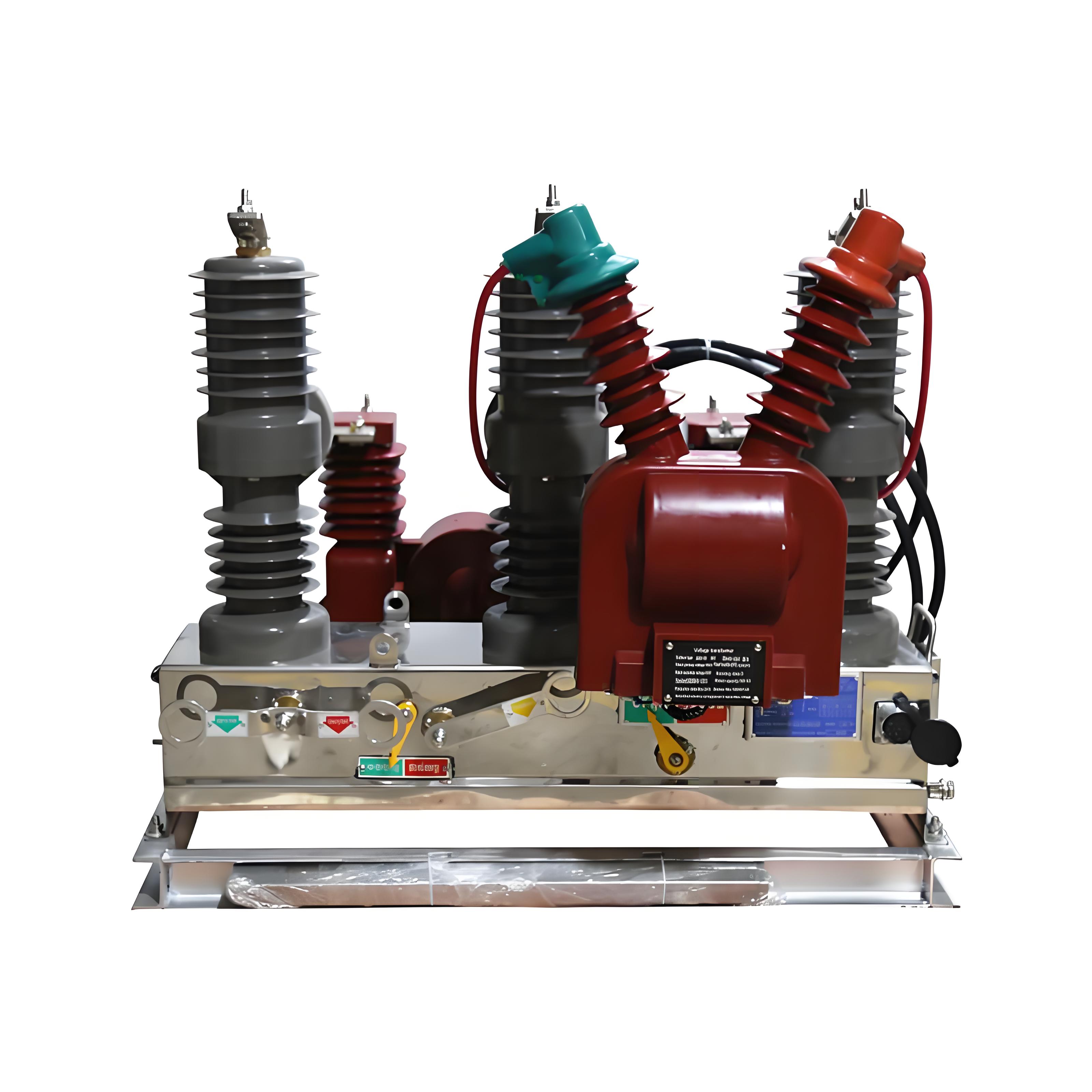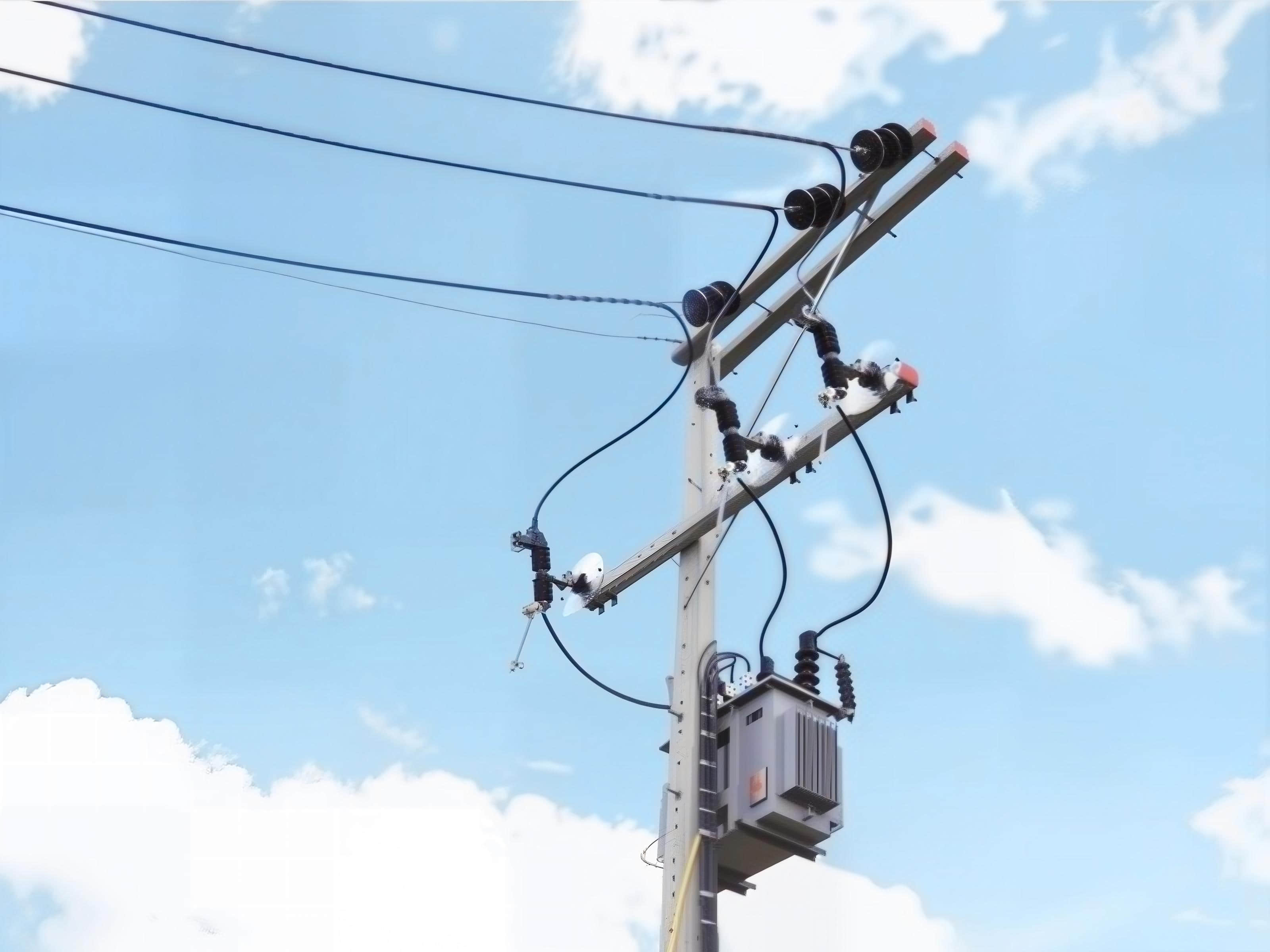
In medium-voltage distribution, a drop out fuse looks simple. In practice, it is one of the most consequential protection components on the pole.
Choose it well, and you prevent transformer burnouts, shorten outage duration, and control field maintenance costs. Choose it poorly, and you create nuisance operations, weak coordination, and expensive equipment losses that travel straight to the operating budget.
This guide is written for utility engineers, EPC teams, industrial power managers, distributors, and field maintenance supervisors who need a practical, business-first reference. It focuses on how to select, size, apply, inspect, and replace a transformer drop out fuse with real-world decision logic rather than textbook abstraction.
What Is a Drop Out Fuse and Why It Matters in Transformer Protection
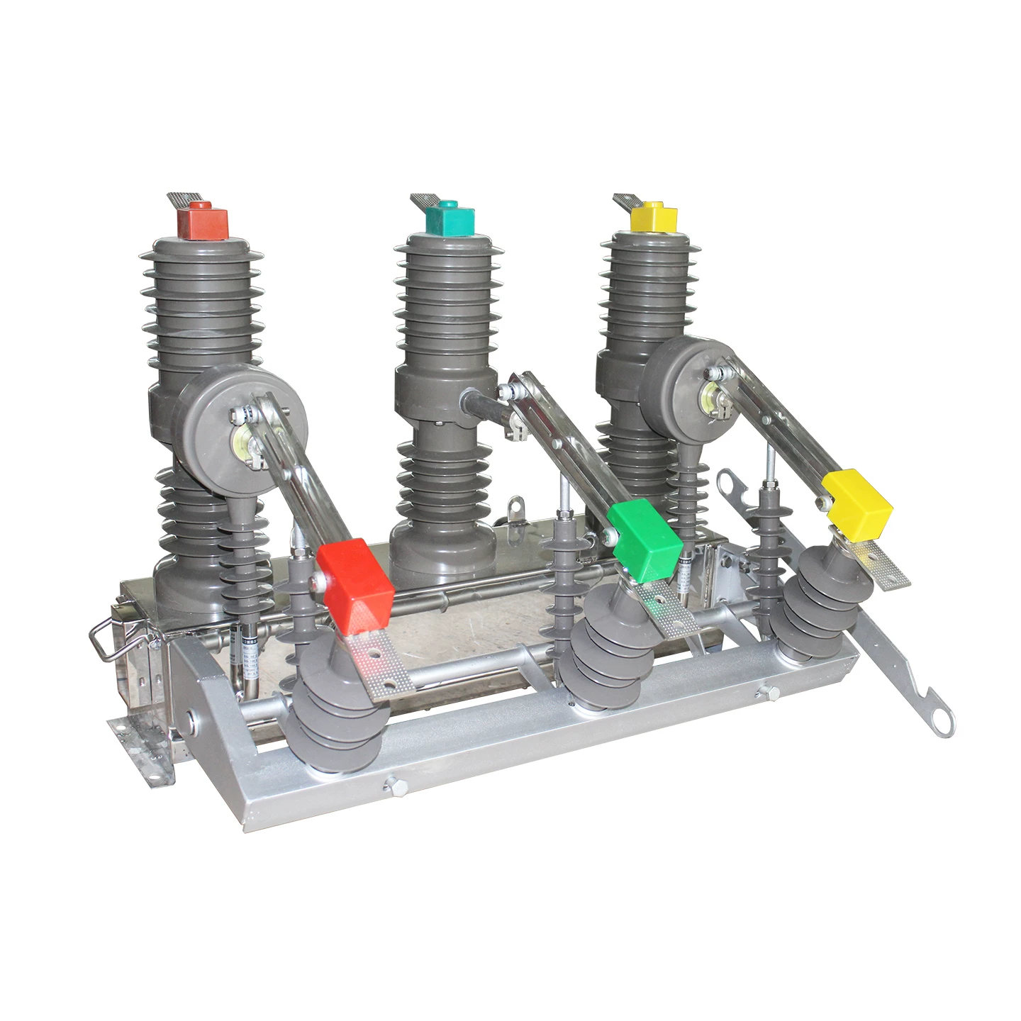
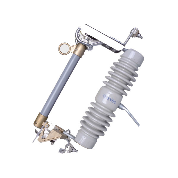
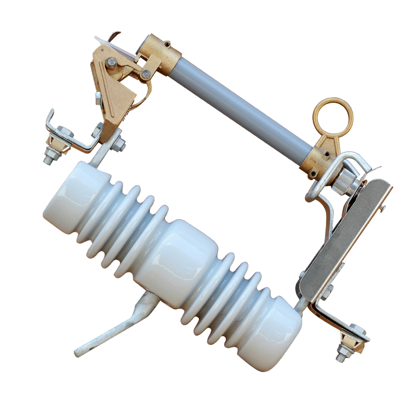
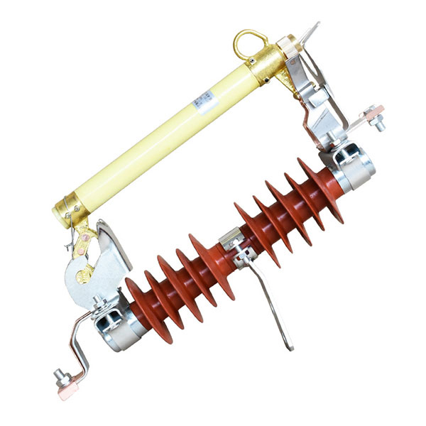
A drop out fuse is an outdoor medium-voltage protective device that combines a fuse link and a hinged fuse tube. When fault current exceeds the fuse link capability, the link melts, the tube releases, and the lower end drops open visibly.
That visible open position is not a small detail. It gives line crews immediate confirmation that the protected branch or transformer has been isolated.
In transformer protection, the transformer dropout fuse function is to interrupt overcurrent conditions before thermal and mechanical damage spreads into the transformer windings, bushings, or upstream line section. This is the core of distribution transformer fuse protection in overhead networks.
The drop out fuse purpose is straightforward: protect assets, localize faults, and simplify restoration. That is exactly why dropout fuses are used on power lines across utility, industrial, and rural distribution systems worldwide.
They remain popular because they are cost-effective, visible, easy to coordinate, and practical in overhead service. For pole-mounted transformers, lateral taps, and capacitor banks, they often provide the best balance between performance and lifecycle cost.
The Cost of Wrong Fuse Selection in Distribution Transformer Systems
Wrong fuse selection rarely fails quietly. It shows up as repeated service calls, customer complaints, transformer overheating, and protection miscoordination.
One common error is oversizing the fuse link to avoid nuisance operations. That may reduce temporary trips, but it also weakens true fault protection and can allow damaging energy to reach the transformer.
The opposite mistake is undersizing. That often causes operations during transformer energization, cold load pickup, or temporary downstream disturbances.
From a business perspective, poor transformer primary fuse selection creates five direct cost channels:
Unplanned outage cost: lost production, SLA penalties, and customer dissatisfaction.
Asset damage: transformer replacement, pole hardware replacement, and secondary equipment damage.
Emergency labor: overtime dispatches, traffic control, switching coordination, and contractor callouts.
Safety exposure: repeat live-line interventions and increased field risk during fault response.
Inventory inefficiency: carrying the wrong fuse ratings and emergency buying at premium prices.
In utility practice, nuisance operations are not just an inconvenience. They consume crew hours, lengthen SAIDI and SAIFI exposure, and distort maintenance planning.
For example, a 100 kVA to 315 kVA pole-mounted transformer bank serving mixed agricultural loads may experience frequent magnetizing inrush, motor starts, and seasonal current swings. If fuse sizing ignores inrush and coordination, operations may spike during restoration after storms, even when no permanent fault exists.
That is why transformer overcurrent protection fuse sizing must be treated as a reliability decision, not just a purchasing line item.
How a Transformer Drop Out Fuse Works
The dropout fuse working principle is simple in appearance and precise in function.
Current flows through the upper contact, fuse tube, fuse link, and lower hinge contact. Under normal load, the fuse carries the rated current without operation.
When a short circuit or sustained overcurrent occurs, the fuse link element melts. The arc produced inside the fuse tube is extinguished by the tube’s arc-quenching action, typically using expulsion principles in many common designs.
Once the fuse link separates and mechanical tension is released, the fuse tube drops open by gravity. This produces visible isolation, helping crews identify the operated cutout from the ground.
In overhead distribution systems, that visible status is operationally valuable. Crews do not waste time second-guessing which transformer branch isolated during a feeder event.
In practical terms, the transformer dropout fuse function includes three linked actions:
Detect and interrupt fault current through fuse melting.
Separate visibly to confirm isolation.
Protect the transformer and local branch from prolonged fault exposure.
This is a major reason dropout fuses are used on power lines despite the rise of more advanced automation devices. They remain easy to understand, easy to inspect, and highly effective when properly coordinated.
Core Functions of a Transformer Drop Out Fuse
The field value of a transformer drop out fuse is best understood through its actual protection roles.
1. Overcurrent interruption
The primary role is fault clearing during line-to-ground, line-to-line, or transformer internal faults. This limits heat and mechanical stress on the protected equipment.
2. Transformer isolation
When the fuse operates, the transformer is visibly separated from the energized primary system. This speeds up fault identification and controlled restoration.
3. Line section protection
On laterals and taps, a drop out fuse can isolate a faulted branch without requiring the entire upstream feeder to remain out of service for long.
4. Backup protection for downstream equipment
In some configurations, it supports coordinated protection for secondary faults or downstream equipment, though this depends on the time-current relationship with upstream devices.
5. Practical electrical protection in outdoor networks
Electrical protection with dropout fuse is valued because it is simple, rugged, and visible. In harsh outdoor conditions, fewer moving parts often means more predictable service life.
Where transformers are pole-mounted and geographically dispersed, the ability to protect each unit economically matters. That is exactly where the advantages of drop out fuse in distribution systems become obvious.
Where Drop Out Fuses Are Used on Power Lines and Distribution Networks
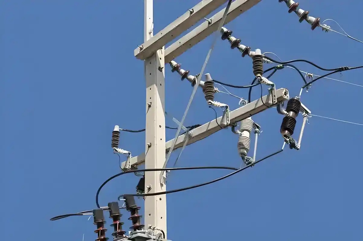
If you walk a typical overhead distribution feeder, you will find drop out fuse applications in several recurring locations.
Pole-mounted distribution transformers: the most common use case.
Lateral taps: to sectionalize branches and reduce outage spread.
Capacitor banks: for local protection and isolation.
Rural feeder branches: where low-cost visible protection is essential.
Industrial outdoor transformer yards: especially where simple medium-voltage protection is preferred.
Small substations or switching points: as part of backup or localized protection schemes.
In many emerging and mature utility markets, dropout cutouts remain standard for 11 kV and 33 kV overhead transformer protection. The reason is not tradition alone.
They solve a practical problem: how to protect many distributed assets without installing expensive interrupting devices at every point.
That is also why dropout fuses are used on power lines in large volumes even today. Their economics scale well in broad rural and suburban networks.
Drop Out Fuse vs Other Transformer Protection Devices
No single protection device is ideal for every location. A clear comparison helps avoid over-specifying one site and under-protecting another.
| DEVICE | MAIN STRENGTH | MAIN LIMITATION | TYPICAL BEST USE |
|---|---|---|---|
| Drop out fuse | Low cost, visible isolation, simple maintenance | Single-operation device, manual replacement required | Pole-mounted transformers, laterals, rural overhead networks |
| Expulsion fuse | Effective fault interruption in outdoor service | May not provide the same operational convenience as cutout format | General outdoor overcurrent protection |
| Circuit breaker | Resettable, high control capability, remote operation possible | High capital and maintenance cost | Substations, critical industrial feeders |
| Recloser | Automatic restoration for temporary faults | More complex coordination and higher cost | Main feeder and important lateral automation |
| Load break switch | Switching under load, operational flexibility | Not a fault-clearing substitute unless paired appropriately | Sectionalizing and switching duty |
The advantages of drop out fuse in distribution systems are strongest when you need low capital cost, visual status, and straightforward field servicing. That is why it remains dominant for large numbers of individual distribution transformers.
However, a drop out fuse is not a magic device. It must be coordinated with upstream breakers or reclosers, and it must suit the transformer inrush and fault profile.
How to Select the Right Transformer Primary Fuse
Good transformer primary fuse selection balances two competing goals. The fuse must survive normal energization and temporary current phenomena, but it must still clear damaging faults before the transformer is compromised.
A practical selection process should follow this sequence:
Confirm system voltage and equipment insulation class.
Determine transformer kVA and primary full-load current.
Review expected inrush current and duration.
Check available fault current at the installation point.
Coordinate with upstream recloser or breaker curves.
Review downstream protective devices and secondary fault exposure.
Select cutout current frame and fuse link rating.
Verify mechanical and environmental suitability.
This is the heart of transformer overcurrent protection fuse sizing. The process is technical, but the objective is commercial: fewer outages, lower replacement cost, and cleaner protection coordination.
Key Inputs Needed Before Fuse Selection
Before selecting a fuse link, gather the following data. Missing even one item can lead to an expensive mismatch.
Voltage class: 11 kV, 22 kV, 27 kV, 33 kV, or local nominal system class.
BIL: basic insulation level must match network and environmental requirement.
Transformer rating: kVA, cooling class, impedance if available.
Primary full-load current: calculate from transformer rating and system voltage.
Ambient conditions: pollution, altitude, temperature, coastal contamination, UV exposure.
Upstream protection devices: breaker, recloser, sectionalizer, relay settings.
Downstream protection devices: LV breaker/fuse arrangement and fault behavior.
System grounding method: affects fault magnitude and protection response.
Load pattern: motor starts, cold load pickup, seasonal demand swings.
Professional buyers increasingly require documented test reports, type test compliance, and interchangeability evidence. In actual sourcing work, teams often compare suppliers on details that only show up after installation: whether the hinge seats cleanly, whether the contacts hold pressure after a hot summer, and whether replacement parts arrive on time. That is where manufacturers such as Weisho Electric tend to be judged in the real world, not just on the datasheet.
Fuse Sizing Rules for Typical Distribution Transformers
There is no universal one-line rule for all utilities, because coordination philosophies differ. Still, field practice follows several workable principles.
Start with transformer primary full-load current.
Select a fuse link above normal full-load current.
Allow margin for magnetizing inrush and cold load pickup.
Check that the selected link will still clear internal transformer faults fast enough.
Verify coordination with upstream recloser fast and delayed curves.
Avoid using nuisance-operation history as the only reason to jump multiple fuse sizes upward.
As a rough reference, many utilities size primary fuse links in a practical band above calculated full-load current, then validate against time-current curves. For example, a transformer with a primary full-load current of around 5 A may use a larger fuse link than 5 A because energization inrush can be many times full-load current for a short duration.
Typical inrush can reach 8 to 12 times rated current, and in some cases higher, depending on switching angle, residual flux, transformer design, and system conditions. That is exactly why spreadsheet-only selection fails when time-current coordination is ignored.
Drop Out Fuse Sizing Table for Common Transformer Ratings
The table below provides practical, real-world style examples for quick evaluation. These are not substitutes for utility standards or manufacturer time-current curves, but they are useful starting points for common outdoor distribution applications.
Typical Primary Fuse Ratings by Transformer kVA and Voltage
| TRANSFORMER RATING | VOLTAGE CLASS | APPROX. PRIMARY FULL-LOAD CURRENT | TYPICAL FUSE LINK RANGE | COMMON APPLICATION NOTE |
|---|---|---|---|---|
| 25 kVA | 11 kV | 1.31 A | 2 A to 3 A | Small rural service transformer, light diversified load |
| 50 kVA | 11 kV | 2.62 A | 3 A to 5 A | Residential or farm service with moderate inrush tolerance |
| 100 kVA | 11 kV | 5.25 A | 6 A to 8 A | Common pole-mounted transformer for village or commercial cluster |
| 200 kVA | 11 kV | 10.50 A | 10 A to 15 A | Mixed commercial/agricultural load, check motor starting profile |
| 315 kVA | 11 kV | 16.53 A | 20 A to 25 A | Frequent industrial branch use, coordination critical |
| 100 kVA | 22 kV | 2.62 A | 3 A to 5 A | Higher voltage class reduces primary current |
| 200 kVA | 22 kV | 5.25 A | 6 A to 8 A | Useful for compact overhead distribution points |
| 315 kVA | 22 kV | 8.27 A | 10 A to 12 A | Check upstream recloser coordination carefully |
| 500 kVA | 27 kV | 10.69 A | 12 A to 20 A | Typical medium-duty branch transformer application |
| 750 kVA | 27 kV | 16.04 A | 20 A to 25 A | Industrial or feeder support transformer |
| 500 kVA | 33 kV | 8.75 A | 10 A to 15 A | Common utility outdoor installation |
| 1000 kVA | 33 kV | 17.50 A | 20 A to 30 A | Higher fault studies required before final selection |
These values assume three-phase transformer current based on standard formula and typical field practice. Final sizing must be confirmed against the transformer maker’s recommendations, utility coordination philosophy, and the specific drop out fuse time-current characteristics.
11kV Drop Out Fuse Selection and Specification
The 11kv drop out fuse is one of the most commonly sourced configurations in medium-voltage overhead distribution. It is widely used for pole-mounted transformers, line taps, and capacitor bank protection.
When buyers search for 11kv drop out fuse specification, they usually need more than voltage class. They need a combination of mechanical, dielectric, thermal, and interruption data.
In commercial tenders, the most important checkpoints usually include:
Rated maximum voltage
Rated continuous current of the cutout base
Interrupting capacity
BIL level
Creepage distance
Fuse link compatibility range
Porcelain or polymer insulation type
Mounting details and interchangeability
For utilities operating in polluted coastal or industrial zones, creepage distance and insulator material deserve more attention than buyers sometimes give them. A cheap unit that tracks, cracks, or loses contact pressure early is not cheap after the second truck roll.
Typical 11kV Drop Out Fuse Specifications
| PARAMETER | TYPICAL VALUE RANGE | FIELD RELEVANCE |
|---|---|---|
| Rated voltage | 12 kV to 15 kV class | Suitable for nominal 11 kV systems depending on standard |
| Rated continuous current | 100 A or 200 A | Defines the cutout frame capability, not just fuse link size |
| Fuse link ratings | 1 A to 40 A commonly used | Selected based on transformer size and coordination |
| Interrupting capacity | 8 kA to 12.5 kA typical | Must exceed available fault current at installation point |
| BIL | 95 kV to 110 kV typical | Critical for insulation performance during surges |
| Creepage distance | 300 mm to 500 mm or more | Important for pollution and humidity performance |
| Insulator material | Porcelain or polymer | Affects contamination resistance, weight, and handling |
| Mounting | Pole bracket / cross-arm mounting | Check retrofit compatibility with existing hardware |
For 11 kV applications, it is common to see 100 A frames used with much smaller fuse links for transformer protection. Buyers should not confuse the cutout frame current rating with the selected fuse link operating rating.
27kV and 33kV Drop Out Fuse Applications
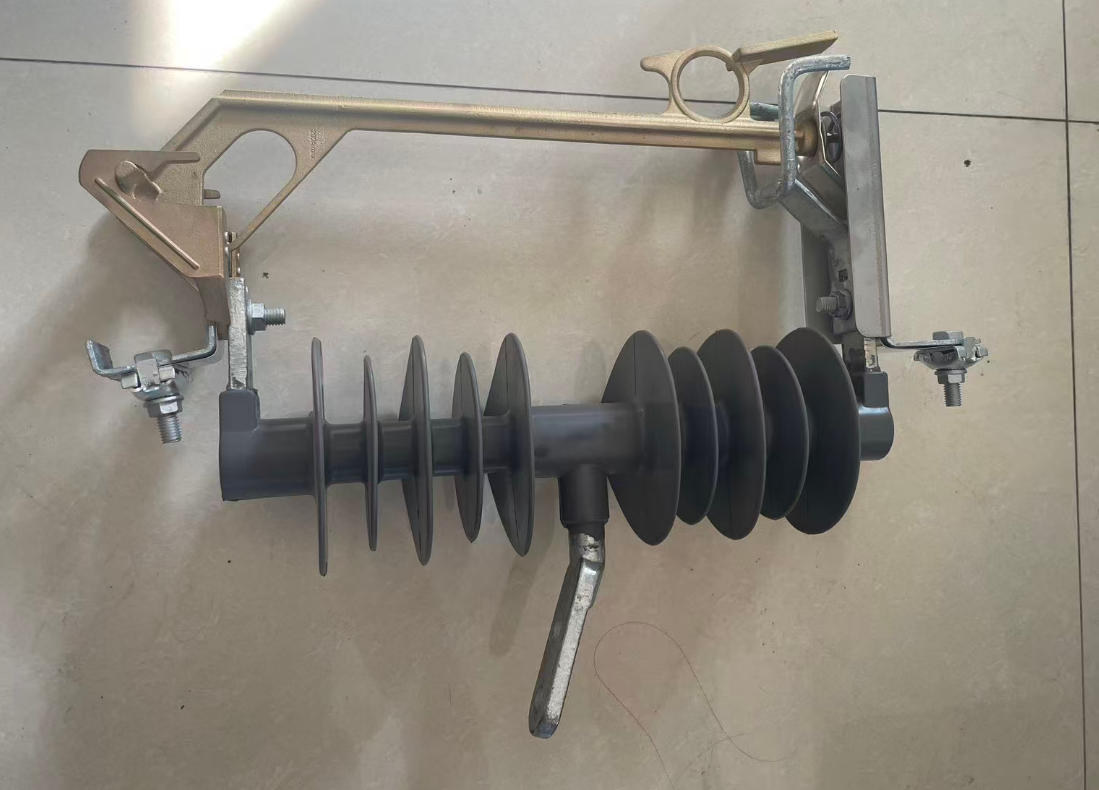
Higher voltage distribution systems demand more attention to insulation, arc interruption, and environmental margin. That is especially true for drop out fuse 27kv 100a and 33kv drop out fuse applications.
A drop out fuse 27kv 100a usually refers to a 27 kV class cutout with a 100 A continuous current frame. It does not mean the fuse link must be 100 A. In transformer protection, the actual link may be much lower.
For 33kv drop out fuse installations, BIL, creepage distance, line hardware geometry, and altitude can become more decisive. In exposed terrain, the consequences of under-specifying insulation margins can be severe.
These higher voltage cutouts are often used in:
Utility overhead transformer protection
Feeder branch sectionalizing support
Outdoor substations for auxiliary transformer protection
Industrial estates with overhead medium-voltage distribution
Typical 27kV 100A and 33kV Drop Out Fuse Data
| PARAMETER | 27KV 100A CLASS | 33KV CLASS | APPLICATION NOTE |
|---|---|---|---|
| Rated voltage class | 27 kV | 33 kV to 38 kV class | Match local system standard and maximum operating voltage |
| Continuous current frame | 100 A | 100 A or 200 A | Frame rating is not the same as fuse link rating |
| Common fuse link options | 3 A to 40 A | 3 A to 50 A | Actual link based on transformer and coordination study |
| BIL typical | 125 kV to 150 kV | 150 kV to 170 kV | Higher insulation withstand for surge exposure |
| Interrupting capacity | 10 kA to 12.5 kA typical | 10 kA to 12.5 kA or higher | Check available fault level carefully |
| Creepage distance | 600 mm and above typical | 900 mm and above typical | Pollution severity may require longer creepage |
| Typical use | Medium-size transformer or branch protection | Higher voltage rural/utility transformer protection | Environmental fit is as important as electrical fit |
For projects sourcing across multiple voltage levels, consistency matters. Buyers usually notice very practical things first: whether the catalog data matches the delivered unit, whether mounting dimensions are consistent from batch to batch, and whether test documents are easy to verify during approval. Suppliers such as Weisho Electric are often shortlisted because those details make field replacement and project delivery far less painful.
Real-World Example: Distribution Transformer Fuse Protection in the Field
Let’s look at a practical scenario drawn from typical utility experience.
A regional distribution operator serving mixed rural-commercial loads had recurring nuisance operations on 11 kV pole-mounted transformers after feeder restoration. The area included irrigation motors, small workshops, and long laterals with storm exposure.
The original protection setup used aggressively small primary fuse links chosen mainly from steady-state transformer current. Magnetizing inrush and cold load pickup were not adequately considered.
After a review, the utility updated distribution transformer fuse protection through three actions:
Recalculated transformer full-load current by kVA and voltage class.
Adjusted fuse link ratings using inrush-tolerant coordination logic.
Verified coordination with upstream recloser fast and delayed curves.
Over the next 12 months, nuisance operations dropped materially. Crews reported fewer unnecessary dispatches, and outage restoration became more targeted because fuse operation better aligned with actual faulted equipment.
Before-and-After Results from Correct Fuse Coordination
| METRIC | BEFORE COORDINATION UPDATE | AFTER COORDINATION UPDATE | BUSINESS IMPACT |
|---|---|---|---|
| Annual nuisance fuse operations | 29 | 8 | Reduced truck rolls and customer complaints |
| Transformer failures linked to prolonged fault stress | 6 | 2 | Lower capital replacement cost |
| Average restoration time per event | 142 minutes | 79 minutes | Improved service continuity |
| Emergency maintenance dispatches | 41 | 17 | Lower overtime and contractor exposure |
| Estimated annual direct maintenance cost | US$48,000 | US$26,500 | Meaningful operating cost reduction |
The lesson is simple. Better transformer primary fuse selection is not theoretical engineering hygiene. It has measurable financial return.
Common Failure Modes and Troubleshooting for Drop Out Fuses
Even a correctly selected drop out fuse can underperform if field conditions or hardware condition are poor.
The most common failure modes include:
Blown fuse links: due to real faults, inrush mis-sizing, or poor coordination.
Poor contact tension: leads to heating, oxidation, and erratic operation.
Contamination: dust, salt, and industrial pollution causing tracking or flashover risk.
Miscoordination: upstream device trips before the local cutout, or the cutout operates too often for temporary events.
Wildlife events: birds, snakes, and squirrels causing transient or permanent faults.
Aging hardware: weakened hinges, eroded contacts, cracked insulators, or degraded fuse tubes.
Incorrect replacement parts: non-matching links, tubes, or hardware reducing interrupting performance.
Troubleshooting should not stop at “the link blew.” That is a symptom, not the root cause.
Ask these questions:
Was there a confirmed downstream or transformer fault?
Did operation happen during energization or restoration?
Is there visible arc damage on contacts or tube ends?
Are there signs of moisture ingress, pollution tracking, or animal contact?
Did upstream recloser operation stress the fuse unnecessarily?
Was the installed fuse link actually the intended rating?
Teams that document these findings consistently build better replacement strategy and better stocking plans.
Transformer Cutout Fuse Replacement Best Practices
Transformer cutout fuse replacement should be treated as a controlled maintenance task, not a quick swap done on habit. Many repeat failures come from replacing the link but ignoring the degraded cutout around it.
A business-focused replacement process should include the following steps:
Verify isolation and safety status according to utility or plant switching procedures.
Inspect the operated cutout visually before removing evidence of failure.
Confirm fault cause if possible before re-energization.
Check fuse tube condition for cracking, carbonization, or severe arc wear.
Inspect upper and lower contacts for erosion, loss of spring pressure, and discoloration.
Confirm insulator integrity including tracking, chipping, and contamination.
Install the correct fuse link rating per protection coordination record.
Check mechanical seating and hinge alignment carefully.
Re-energize under controlled conditions and observe system response.
Record the event for asset history and reliability analysis.
One of the most common field errors is replacing a blown link with the next larger size “to keep it from blowing again.” That shortcut often turns a coordination problem into a transformer loss.
Replacement Inspection Checklist
| INSPECTION ITEM | WHAT TO CHECK | WHY IT MATTERS |
|---|---|---|
| Insulator condition | Cracks, chips, contamination, tracking marks | Prevents flashover and insulation failure |
| Hinge alignment | Straight seating, free movement, proper engagement | Ensures reliable dropout action and contact fit |
| Fuse tube wear | Carbonization, cracking, moisture damage, end fitting wear | Affects interruption and mechanical reliability |
| Upper/lower contacts | Erosion, pitting, oxidation, contact pressure | Reduces hot spots and nuisance failure risk |
| Terminal torque | Secure line and equipment connections | Loose joints create heating and voltage stress |
| Arc damage | Metal spatter, burn marks, structural distortion | Identifies severe fault energy or poor interruption |
| Fuse link rating | Correct part number and ampere rating | Maintains coordination integrity |
| Mounting hardware | Corrosion, bracket strength, fastener integrity | Supports long-term mechanical stability |
Installation, Maintenance, and Safety Standards to Follow
Installation quality has a direct effect on service life. A premium cutout installed with poor alignment or weak connections will still fail early.
Best practice areas include:
Inspection interval planning: more frequent checks in coastal, polluted, or high-lightning regions.
Cleaning and contamination control: especially where salt fog or industrial dust is present.
Torque and connection checks: loose primary connections are a hidden source of heating.
Live-line work procedures: only where approved tools, methods, and trained personnel are in place.
Fuse link compatibility control: avoid mixed components without qualification.
Post-fault assessment: do not assume a replaced link means the equipment is ready for normal service.
Applicable standards depend on jurisdiction and buyer practice, but teams commonly reference IEC, IEEE, ANSI, and local utility standards for cutout design, test performance, insulation coordination, and safe operation. The exact standard set should be specified in procurement documents.
For international projects, ask suppliers to provide:
Type test reports
Routine test records
Material specifications
Dimensional drawings
Installation instructions
Recommended maintenance practices
That paperwork is not bureaucracy. It is part of operating discipline.
Buying Checklist: How to Evaluate a Drop Out Fuse Supplier
Buying a drop out fuse purely by price is a common procurement mistake. Medium-voltage outdoor protection should be evaluated on total lifecycle value.
Use this supplier checklist:
Compliance: Are there valid test certificates for the offered voltage and current class?
Design consistency: Are dimensions and mounting interfaces stable across batches?
Material quality: What insulator material, contact plating, and tube construction are used?
Interrupting performance: Is the published fault interrupting capability adequate?
Lead time reliability: Can the supplier meet emergency and project schedules?
Interchangeability: Can the product retrofit existing utility hardware where required?
Lifecycle cost: What is the expected field life versus the purchase price?
Technical support: Will the supplier help with selection sheets, drawings, and troubleshooting?
After-sales responsiveness: Are claims and technical questions handled quickly?
The best suppliers act like technical partners, not carton shippers. They help verify application data, clarify fuse link compatibility, and support replacement planning across voltage classes.
FAQ
What is the purpose of a transformer drop out fuse?
The purpose of a transformer drop out fuse is to protect a distribution transformer from overcurrent and fault conditions by interrupting damaging current on the primary side. It also provides visible isolation after operation, which helps crews identify and safely manage the faulted transformer branch.
How does a drop out fuse work on a power line?
The dropout fuse working principle is that current passes through a fuse link inside the fuse tube during normal operation. When fault current exceeds the fuse capability, the link melts, the arc is interrupted inside the tube, and the tube drops open visibly, which is one key reason dropout fuses are used on power lines.
How do I choose the correct transformer primary fuse size?
Start with transformer kVA and system voltage to calculate primary full-load current. Then account for magnetizing inrush, available fault current, and coordination with upstream and downstream protective devices before selecting the final fuse link rating for proper transformer primary fuse selection.
What is the difference between an 11kV drop out fuse and a 33kV drop out fuse?
An 11kv drop out fuse and a 33kv drop out fuse differ mainly in voltage class, insulation level, BIL, creepage distance, and often physical size. The 33 kV unit must withstand higher electrical stress and is typically designed for more demanding insulation and environmental requirements.
What does drop out fuse 27kV 100A mean?
Drop out fuse 27kV 100A usually means the cutout is built for a 27 kV class system and has a 100 A continuous current frame rating. It does not mean the installed fuse link must be 100 A, because the actual link is selected separately based on transformer protection needs.
When should a transformer cutout fuse be replaced?
Transformer cutout fuse replacement is required after a fault operation and also when inspection shows visible damage, contact erosion, cracked insulators, weakened hinges, severe contamination tracking, or aged hardware that could compromise safe performance. Replacement should include inspection of the whole assembly, not just the fuse link.
What are the advantages of drop out fuse in distribution systems?
The main advantages of drop out fuse in distribution systems are low cost, simple construction, visible isolation, easy field maintenance, and effective transformer overcurrent protection. They are especially valuable for overhead distribution transformers and lateral branches where utilities need dependable protection at scale.
Conclusion: Turn Fuse Selection into a Reliability and Cost-Control Advantage
A drop out fuse is not a commodity in the real operating sense. It is a frontline protection device that directly influences outage frequency, transformer life, field labor, and safety exposure.
When transformer overcurrent protection fuse sizing is done correctly, the benefits compound. You get fewer nuisance outages, better coordination with upstream devices, lower transformer damage risk, and more disciplined maintenance planning.
When it is done poorly, the losses are predictable: repeat callouts, asset failure, customer dissatisfaction, and hidden maintenance cost inflation.
The smartest operators treat distribution transformer fuse protection as both an engineering issue and a business control point. That mindset separates reactive maintenance organizations from reliable ones.
CTA: Request a Drop Out Fuse Selection Sheet or Expert Quote
If you are evaluating a new drop out fuse, upgrading an existing transformer protection scheme, or planning transformer cutout fuse replacement, now is the time to get the sizing right.
Send your transformer kVA, system voltage, installation environment, and application details to request a recommended specification, practical sizing table, or replacement plan.
Contact us today for an expert quote and a tailored drop out fuse selection sheet that helps you reduce outages, protect transformers, and control lifecycle cost.