A potential transformer scheme chosen only for metering can leave a feeder with no single-phase ground-fault alarm. On a cable-heavy busbar, the same scheme can also leave PTs burning out from ferroresonance. The four potential transformer connection methods differ in which voltages reach the relay and in how each behaves when the neutral shifts.
The four schemes are a single-phase connection (one PT across A–C), the V-V or Open Delta connection (two PTs), the YNyn+d connection with three PTs, and a four-PT scheme with a neutral anti-resonance PT. V-V suits line-voltage metering. YNyn+d adds ground-fault detection. Four PTs are the safer choice where cable capacitance invites resonance.
Voltage Transformer Connection Types and What Each Measures
Voltage transformer connection types fall into two groups. Phase-to-phase schemes deliver line voltages only, and star schemes with a grounded primary neutral also deliver phase and zero-sequence voltages. The scheme sets the ceiling on what any downstream meter or relay can see, so settle it before you look at winding ratings or accuracy classes.
The comparison below shows each scheme against the quantities it can actually supply to secondary equipment.
| Scheme | Number of PTs | Primary connection | Secondary connection | Measured quantities |
|---|---|---|---|---|
| Single-phase connection | 1 | Across phases A and C | Single-phase output | Uac only |
| V-V connection (Open Delta) | 2 | AB and BC | V-shaped | Uab, Ubc, Uca |
| YNyn+d connection (Star-Star with Open Delta) | 3 | Star, neutral grounded | Star main, open-delta auxiliary | Line, phase, zero-sequence voltages |
| 4-PT anti-resonance scheme | 4 | Star, fourth PT neutral-to-ground | Star, grounded via compensation winding | Line, phase, zero-sequence voltages |
Only the bottom two rows can report zero-sequence voltage. In practice, that one column decides most specifications.
Terms you will see on drawings and datasheets
A line voltage is the voltage measured between two phases, such as Uab. A phase voltage is the voltage from one phase to neutral or ground, such as Ua. Zero-sequence voltage is the component common to all three phases. It is close to zero in a balanced system and rises sharply when one phase touches ground. An open-delta winding is a set of three auxiliary secondary windings connected head-to-tail with one corner left open. The voltage across that gap is the residual voltage, which is the vector sum of the three phase voltages and is proportional to the zero-sequence voltage. Ferroresonance is a sustained oscillation between the nonlinear inductance of a PT core and the system capacitance. It can drive overvoltages and heavy PT primary currents, which is the usual cause of blown PT fuses and burnt windings.
PT Wiring Diagram V-V vs Y-Y: Where the Two Families Split
On paper, a V-V diagram and a Y-Y diagram both feed three wires to a voltmeter, and both show three line voltages on the panel display. That surface similarity hides the real difference, which is that one family can see the system's relationship to ground and the other cannot.
Single-phase and open delta potential transformer connection on one or two PTs
The single-phase connection uses one PT with its primary across two phase conductors, usually A and C. The secondary gives one line voltage, Uac. It is the usual choice for voltage sampling on an incoming-feeder panel, where the signal is used for live-line indication, synchronism or a simple undervoltage check.
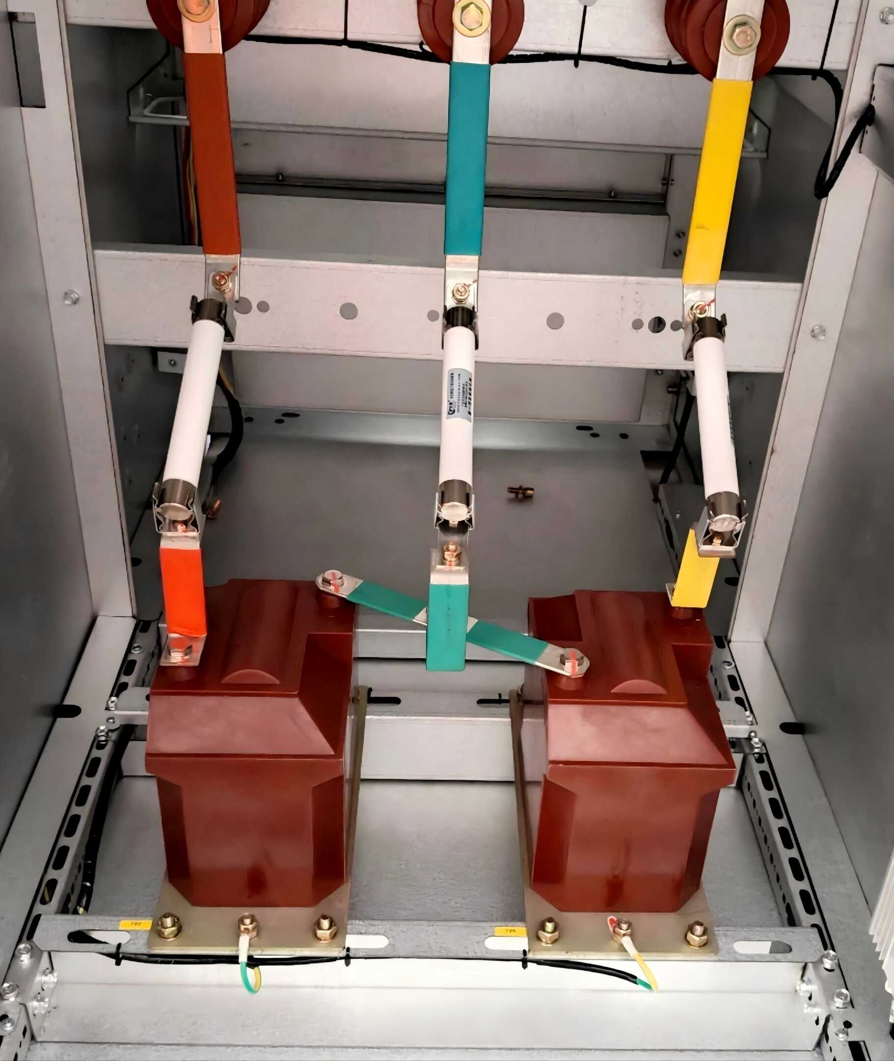
The open delta potential transformer connection, also called V-V, adds a second unit. One PT sits on AB and the other on BC, and the secondaries form a V. Uab and Ubc are measured directly, and Uca is derived from their vector sum, so the panel gets all three line voltages from two PTs. That makes V-V a common choice for busbar three-phase voltage measurement and for energy metering on three-wire systems. The secondary is normally grounded on the shared phase, often phase B.
Both schemes keep the unit count low. That means less panel space, fewer fuses and a smaller bill of materials. But neither has a primary connection to ground. A single-phase fault to earth shifts the neutral point, and the line voltages stay almost unchanged. The V-V secondary therefore reports a healthy system while one phase is grounded.
Yyn and YNyn+d on three PTs
The Yyn connection (Star-Star) uses three single-pole PTs with the primaries in star and the neutral grounded. The secondary main windings are also in star, which gives three phase voltages alongside the three line voltages. The YNyn+d connection adds a second, auxiliary winding on each PT. These auxiliary windings are connected head-to-tail into an open delta. In a balanced system the three voltages around that delta cancel, and the output is close to zero. When one phase goes to ground, the cancellation fails and the delta outputs a residual voltage. That signal drives insulation monitoring and single-phase ground-fault alarms.
In many IEC-market specifications, the main winding is rated 100/√3 V. For ungrounded systems the open-delta winding is typically rated 100/3 V, so a solid ground fault produces roughly 100 V across the delta. Check the rating against the relay input rather than assuming it.
Zero-sequence detection as the real dividing line
Medium-voltage networks with an ungrounded neutral, or with a neutral grounded through an arc-suppression coil (resonant grounding), can keep running for a while with one phase on ground. That is the reason the fault must be found and alarmed rather than tripped instantly. A phase-to-phase scheme cannot do that job. Any bus in such a system that needs insulation monitoring therefore usually gets the star-plus-open-delta scheme. A point that only needs line voltage for metering or synchronism can often stay on V-V and save one unit.
"Open delta" is used for two different things. It can mean the two-PT V-V primary scheme, or it can mean the auxiliary winding that produces residual voltage in a YNyn+d set. A quote for one when the drawing means the other gets the PT count, the winding count and the price wrong. Confirm which one the drawing means before you quote.
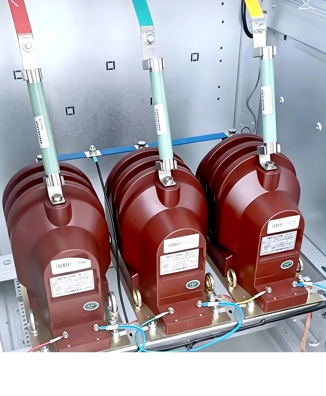
The 4-PT Anti-Resonance Scheme for Cable-Heavy Systems
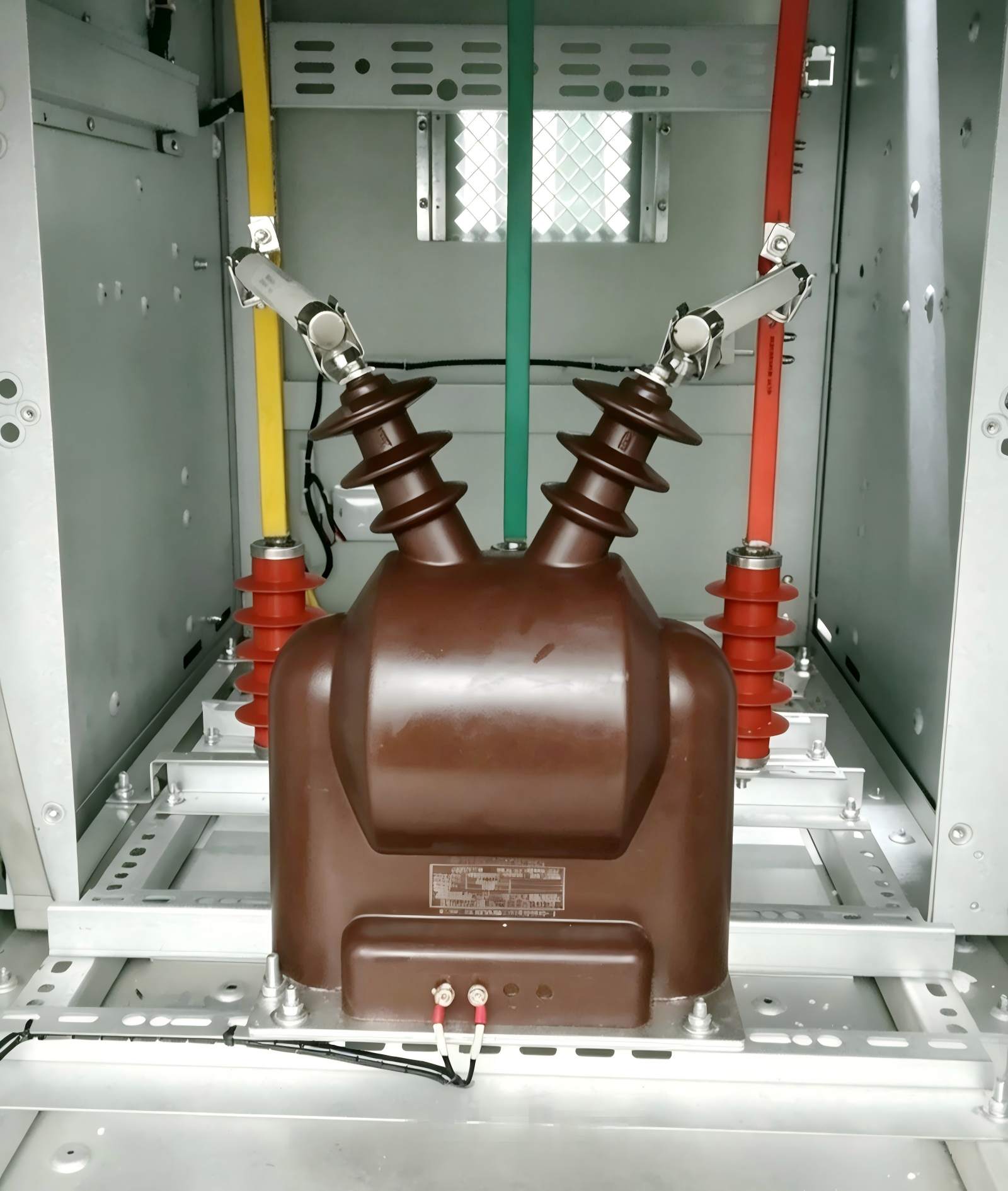
The fourth PT does the damping work. Phases A, B and C each have their own PT. Instead of grounding the common primary neutral directly, a fourth PT, often called a zero-sequence or anti-resonance PT, is connected in series between that neutral and ground. On the secondary side, the star neutral is grounded at a single point through the fourth PT's compensation winding.
The measurement capability matches YNyn+d: line voltages, phase voltages and zero-sequence voltage are all available. The difference shows during a ground fault or an intermittent arcing fault. Most of the zero-sequence voltage then appears across the neutral PT and not across the three-phase PTs. The phase PT cores are therefore less likely to be driven into saturation, and saturation is what starts the ferroresonance loop. The fourth unit absorbs resonance energy at its source instead of letting it build between the PT inductance and the network capacitance.
Where ferroresonance risk is highest
Three situations call for the 4-PT scheme first. The first is busbars with a history of resonance. The second is substations with long cable feeders. The third is any system with high capacitance to ground, which cable networks usually have. In these cases the 4-PT arrangement replaces the external damping resistor that would otherwise be wired across the open delta. That resistor only acts on the secondary side and must be sized to the right value to work.
PT secondary grounding in the 4-PT arrangement
PT secondary grounding has one rule here: one point, through the compensation winding. If someone adds a second ground, for example a direct neutral bond in the relay panel, the compensation winding is bypassed. Currents can then circulate between the two ground points. The zero-sequence reading becomes wrong, and the scheme loses its compensation. This is an easy commissioning mistake, because a second ground looks like extra safety to anyone used to conventional star PT wiring. Check the drawing and the panel wiring together.
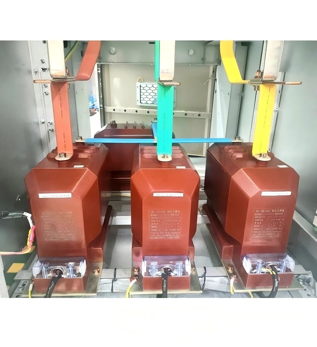
Which Potential Transformer Connection Methods Fit Your Switchgear?
The criteria below are listed in the order they most often settle the choice between potential transformer connection methods.
The first criterion is the set of quantities the downstream devices need. If the relay or multifunction meter requires phase or zero-sequence voltage, a phase-to-phase scheme is ruled out. The second is the system grounding method. Ungrounded and resonant-grounded networks need residual voltage for fault indication. A solidly grounded network clears ground faults through current-based protection, so it relies less on the open delta. The third is whether the specification or the utility explicitly requires a ground-fault or insulation alarm on that bus. The fourth is resonance risk, which depends on cable length and capacitance to ground. Panel space and unit count come last. They matter in compact switchgear but rarely override the first four.
This table maps common panel positions to the scheme usually specified.
| Application | Recommended scheme | Reason |
|---|---|---|
| Incoming-feeder voltage sampling | Single-phase, 1 PT | One line voltage is enough |
| Busbar three-phase metering | V-V, 2 PTs | Three line voltages, fewer units |
| Insulation monitoring, ungrounded system | YNyn+d, 3 PTs | Open delta gives residual voltage |
| Resonance-prone cable networks | 4-PT anti-resonance scheme | Suppresses ferroresonance at the source |
Rule of thumb: if the bus needs to know where ground is, use star with open delta. If it also feeds long cables, add the fourth PT.
Ordering Details to Confirm Before You Send an RFQ
Two quotes for "three PTs" can describe quite different equipment. Line these items up so that every supplier, including Weisho Electric, prices the same specification.
| Item | Why it matters | Applies to |
|---|---|---|
| Rated primary and secondary voltages | Phase-to-ground units carry √3 ratings | All schemes |
| Accuracy class per winding | Metering and protection classes differ | All schemes |
| Number of secondary windings | Open delta needs an auxiliary winding | YNyn+d, 4-PT |
| Open-delta winding rating | Must match residual relay input | YNyn+d, 4-PT |
| Insulation level | Sets the PT for the system voltage | All schemes |
| Applicable standard | IEC 61869-3 or IEEE C57.13 | All schemes |
The open-delta rating and the winding count cause most mismatched quotes. For a 4-PT set, also ask for the neutral PT ratio and its compensation winding data on the same datasheet as the phase units. Weisho Electric and other vendors can only quote a matched anti-resonance set if the four units are specified as one package.
FAQ
Can a V-V connection detect a single-phase ground fault?
No. The V-V primary connects phase to phase with no path to ground, so the line voltages barely change during a ground fault. For fault detection, you need star PTs with a grounded neutral and an open-delta winding.
How do you connect potential transformers in a three-phase system that has an ungrounded neutral?
Use three single-pole PTs in YNyn+d, or four PTs if resonance is a risk. The grounded star primary provides phase voltages. The open-delta auxiliary winding supplies residual voltage to the insulation-monitoring relay.
Does the 4-PT scheme fully replace an external damping resistor?
In most designs, yes. The neutral PT suppresses ferroresonance at the primary side, so a separate resistor across the open delta is usually not required. Confirm with the PT manufacturer's application data for your network capacitance.
Why should a PT secondary be grounded at only one point?
Two ground points create a loop for circulating current. That distorts voltage readings and can cause protection to misoperate. In the 4-PT scheme, a second ground also bypasses the compensation winding and defeats the anti-resonance function.
Choosing Between Two, Three and Four PTs
The choice comes down to how much the bus needs to know about ground. Line-voltage metering can run on two units, but fault awareness and resonance protection require the star family. The next question on most projects is fuse selection and fuse-blowing diagnosis on the PT primary, because that is where a wrong scheme usually shows up first.