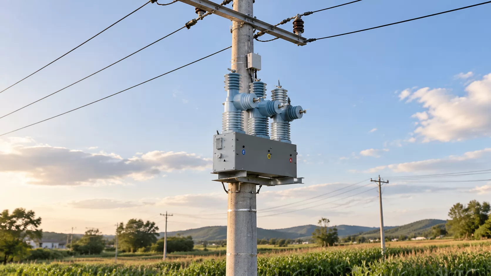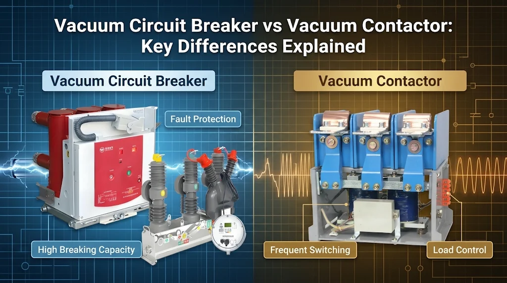
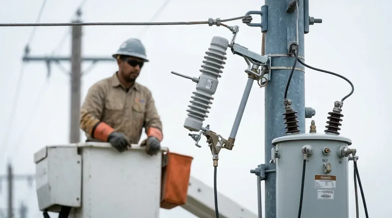
Most people assume a fuse cutout shields a transformer from every kind of overload. The job is narrower than that: it clears short circuits and severe overloads, and it leaves a visible open point on the line. This guide covers how to specify, size, coordinate, and replace the device so it does that narrow job reliably.
A fuse cutout is a fuse-and-switch assembly mounted on the high-voltage side of a distribution transformer. When a short circuit or heavy overload melts the fuse link, the tube drops open, the arc is blown out, and the open point can be seen from the ground. Size the link from the transformer's rated primary current, then check it against the time-current curve.
Key Takeaways
Scope of protection: the device clears transformer internal faults, low-voltage side short circuits and severe overload. It is not a thermal overload relay.
Operation: fault current melts the fuse link, the tube loses tension and drops under its own weight, and gas from the tube lining extinguishes the arc.
Link sizing: start from rated primary current, apply a multiplier for inrush and normal load swings, pick the nearest standard rating, then verify against the curve.
Two separate ratings: the cutout body (voltage, continuous current, interrupting capacity) and the fuse link are different choices and both must be right.
Replacement: isolate per the utility's switching procedure, use a hot stick and rated PPE, and never fit a new link without finding out why the old one blew.
What Is a Drop-Out Fuse, and Where Does It Sit on the Line?
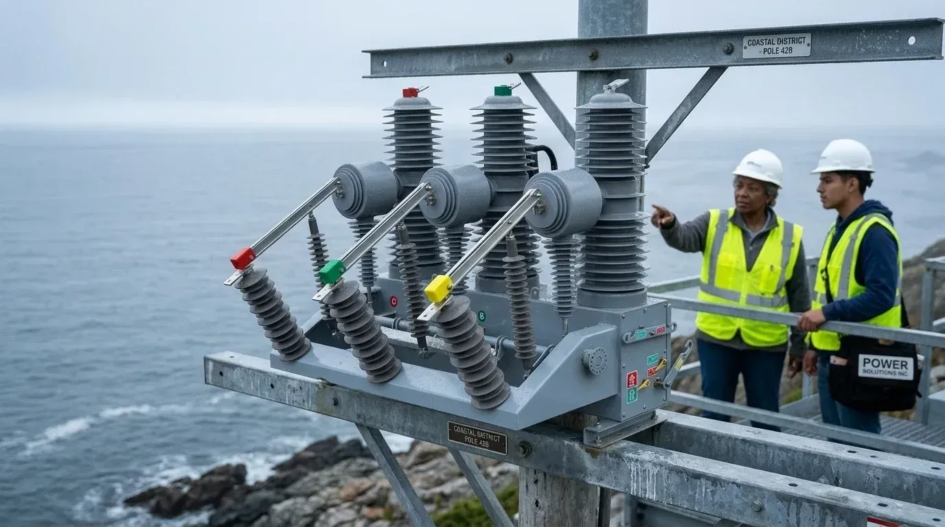
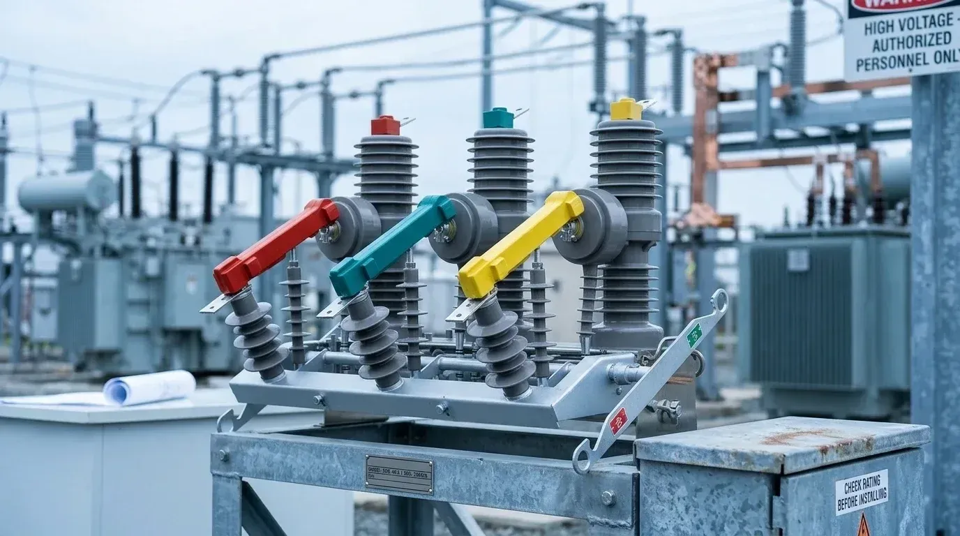
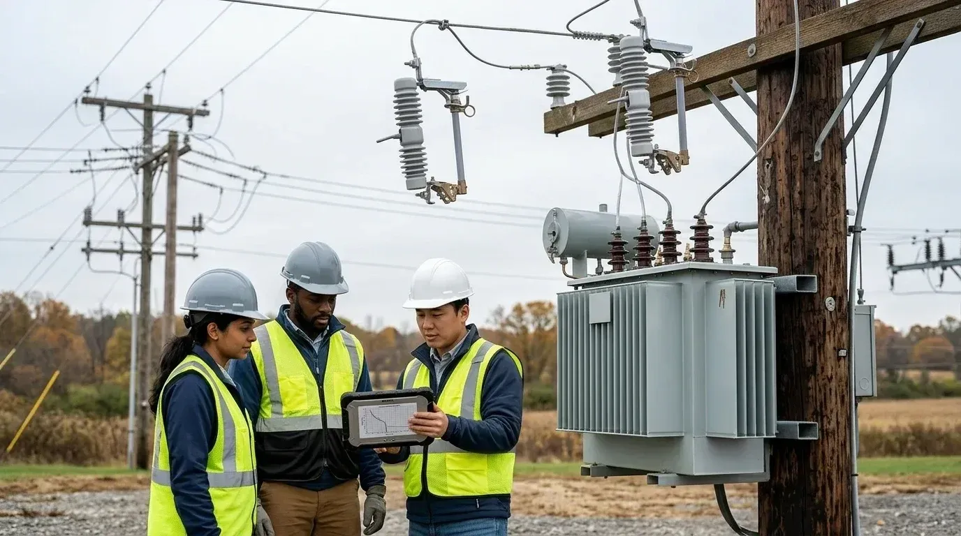
Picture a pole-mounted transformer at the end of a rural 11kV or 33kV branch. Above the transformer, on the crossarm, sit three porcelain or polymer assemblies, one per phase, each with a hinged tube angled downward. Those are the drop-out fuses. A drop-out fuse is a combined protection and switching device that sits on the high-voltage incoming side of a distribution transformer and opens the circuit when its fuse link melts.
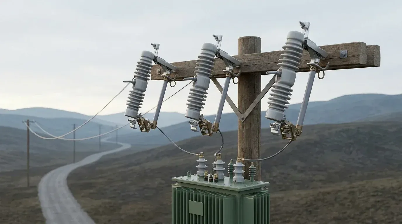
You find them on overhead distribution lines, typically in the 11kV–36kV class, both at transformer tees and at the head of branch lines. They are the common short-circuit protection for branch lines and for the transformers fed from them.
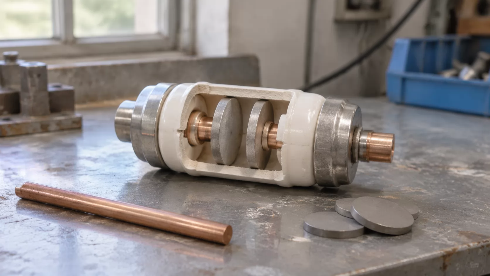
Three parts do the work. The fuse link is the calibrated element that melts. The fuse tube holds the link and carries a gas-producing lining. The insulator supports the whole assembly and keeps it isolated from the crossarm. Contacts at each end of the tube carry current when it is closed.
The protection function is deliberately simple: one inverse-time over-current characteristic, no adjustment, no auxiliary power. That simplicity is why it survives on remote lines for decades, and also why you must get the link choice right. Nothing downstream will correct a poor selection.
Many buyers specify the cutout from a catalogue number copied off an old pole, without checking whether line voltage or fault level has changed since. Weisho Electric supplies drop-out fuse cutouts for this duty, but whoever makes the unit, the match between the device and the line it sits on is the first thing to confirm.
How Does a Fuse Cutout Work When a Fault Hits?
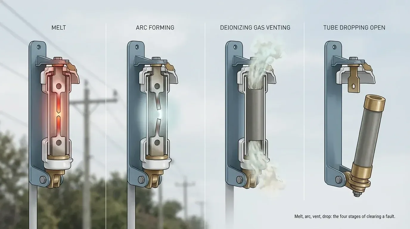
The sequence has four stages, and each one matters for a different reason. Understanding them tells you what to inspect when a unit misbehaves.
Normal operation: the link carries load current
With the tube latched closed, load current flows from the upper contact, through the fuse link, to the lower contact and on to the transformer. The link is held under tension by a spring or button-head arrangement, and that tension is what keeps the tube in its closed position. Under normal load the link runs warm but stays well below its melting point.
Fault: the link melts and the tube drops
A short circuit or severe overload sends current well above the link's rating. The element heats rapidly, reaches its melting temperature and parts. Once it breaks, the tension that held the latch is gone. The tube, free to rotate on its lower hinge, falls under its own weight and swings open.
Arc extinction and drop-out operation
When the element melts, an arc forms across the gap. The tube's inner lining, usually a fibre material, gives off deionizing gas under that heat. The gas builds pressure and vents out the tube ends, which stretches and cools the arc until it cannot sustain itself at the next current zero. This is the expulsion principle, and it is why the link is called an expulsion fuse link.
Why the visible break matters to line crews
A dropped tube hangs at an obvious angle. From the ground, a crew can see which phase has operated without climbing or opening anything. That visible open point also acts as isolation for the transformer side, which speeds fault location and gives maintenance staff a clear indication before work starts. It is not a substitute for the utility's own isolation and earthing procedure, though.
What Faults Does Transformer Fuse Cutout Protection Actually Cover?
Protection from a drop-out fuse cutout for transformer applications covers three situations well: internal short circuits in the transformer, short circuits on the low-voltage side, and severe sustained overload. It does not cover gradual overload, and it does not replace the tank-level protections found on larger units. Knowing where the edge sits is what keeps expectations realistic.
Compare it with a thermal overload device. A thermal device watches temperature and acts on moderate overload over a long time. A cutout link responds to current magnitude along an inverse-time curve, so a modest overload of, say, 120 to 150 percent of rating may sit on the link for a long time without melting it. The transformer insulation, meanwhile, ages quietly. If loading is the concern, you need load monitoring or a different protective scheme alongside the fuse.
Internal faults are a middle case. A winding-to-winding or turn-to-turn fault inside the tank may draw only a small increase in primary current at first. The link may not see enough current to operate quickly, or at all, until the fault develops. That limitation is well known with fuse protection of small distribution units, and it is accepted because the cost of a more sensitive scheme is out of proportion for pole-mounted transformers.
Low-voltage side faults are where the cutout does its best work. A short on the secondary reflects to the primary as a large current, and a correctly chosen link clears it in the time the curve promises.
Note: A fuse cutout is not an overload relay. If a transformer runs hot for hours at 130 percent load, the link may never operate. Track loading separately and replace undersized transformers before the insulation pays for it.
How Does a Fuse Protect an Electrical Circuit From Damage?
The common belief is that a fuse is a barrier that stops current. It is the opposite: a fuse is a deliberately weak point. It is built to fail before the transformer, conductors or switchgear do, and by failing it removes the energy source.
The link is made so its melting behavior is predictable. Too little current and nothing happens. A lot of current and the element heats faster than it can shed heat, so it melts quickly. This gives the characteristic called inverse time: the higher the current, the shorter the clearing time. A fault at ten times rating clears in a fraction of a second, while a mild overload may take minutes.
That shape is useful in two ways. First, it tolerates short harmless events, such as the inrush when a transformer is energized, because they are brief. Second, it clears dangerous events fast enough to limit damage. Let a short circuit sit on a transformer for seconds and you risk tank rupture, oil fire and heavy mechanical stress on windings.
A drop-out fuse adds a second layer to the idea. Besides interrupting, it physically separates. The open tube makes the circuit break visible, which a sealed fuse cannot do.
There is a cost to this approach. A fuse operates once, then needs replacing. Single-phase operation is also possible: if one link blows on a three-phase bank, the other two phases remain energized, and downstream three-phase motors may suffer. For installations with sensitive three-phase loads, that argues for added single-phasing protection on the low-voltage side.
How Do You Calculate the Fuse Size for a Transformer?
To calculate fuse size for a transformer, find its rated primary current from the kVA and line voltage, multiply by a factor that allows for inrush and normal load swings, and choose the nearest standard link rating. Then verify the result on the manufacturer's time-current curve. The multiplier is where judgment enters, so check what your utility standard prescribes.
Find rated primary current. For a three-phase transformer, divide kVA by (√3 × line voltage in kV). For a single-phase unit, divide kVA by the primary voltage in kV.
Apply a multiplier. Utilities commonly choose links rated at roughly 1.5 to 2 times full-load primary current for small units. Lower multipliers protect better but risk nuisance blowing on inrush.
Pick the nearest standard rating. Links come in preferred steps, so round to the closest available value, not a calculated figure that does not exist on the shelf.
Check the curve. Confirm the link survives transformer inrush (often modeled as about 10 to 12 times full-load current for roughly 0.1 second) and still clears a secondary fault before the transformer's through-fault withstand limit is exceeded.
A worked example for a typical pole-mounted unit
Take a 200 kVA three-phase transformer on an 11kV line. Rated primary current is 200 ÷ (1.732 × 11), which is about 10.5 A. Apply a multiplier of about 1.5 to 2 and the target falls roughly between 16 A and 21 A. A link in the 15 A to 25 A range would be the candidate, and the final pick depends on the curve family and the upstream device. Always confirm with the link maker's published curves, and where the utility has a standard fusing table, follow that instead.
What Size Fuse Cutout for a Transformer Is Right: Link Rating or Cutout Rating?
These are two separate choices, and mixing them up is a frequent specification error. The link rating sets when the fuse operates. The cutout body rating sets whether the assembly can safely carry and interrupt what the system throws at it. When asking what size fuse cutout for transformer applications is right, you need to get both ratings right.
Four criteria define the body selection:
System voltage. The cutout's rated voltage must sit above the line's maximum operating voltage, and the insulation level (BIL) must match the system's insulation coordination.
Continuous current. The body's rated current, commonly 100 A or 200 A on distribution cutouts, must exceed the link's rating. A 200 A body housing a 15 A link is normal and sensible.
Interrupting capacity. The cutout must be able to interrupt the maximum available fault current at the installation point, stated in kA symmetrical. Near a substation the fault level can be high enough to rule out lighter-duty units.
Link compatibility. The tube and link must be designed to work together. Not every link fits every tube, and an interrupting rating belongs to the combination, not to either part alone.
The body is selected once, for the pole position. The link is selected per transformer and may change if the transformer is upgraded. Keeping those two decisions apart on your purchase specification avoids a common ordering mistake, where a buyer asks for "a 25 A cutout" and receives a body rated 25 A that cannot handle the system's fault level.
Ask for the fault level at the pole from the network owner, not from memory of the substation size.
K-Type or T-Type Link: Which Time-Current Curve Fits Your Transformer?
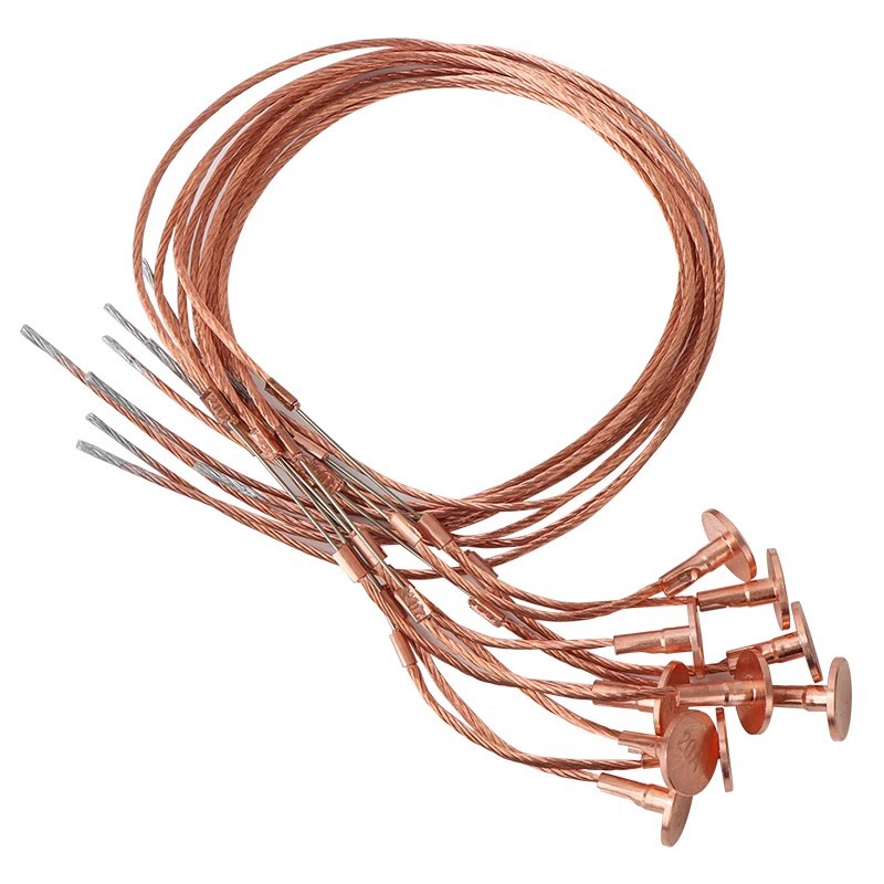
K links are fast; T links are slow. That is the whole distinction in short. A K-type link has a speed ratio of about 6 to 8, and a T-type about 10 to 13, so the T link tolerates more current for longer before it melts. Both are expulsion fuse links standardized in the same family of time-current characteristic curves.
Speed ratio is the ratio of the link's melting time at the 0.1 second point to its melting time at the 300 second point, expressed in current. A lower number means a flatter curve and a faster response to overcurrent.
K links suit transformer protection where you want the fuse to clear secondary faults quickly, and where the upstream device is a recloser or a larger fuse with its own coordination needs. They give the tighter protection but are less forgiving of inrush and cold-load pickup.
T links suit situations where tolerance matters more than speed. A transformer feeding a motor load, a line with long reenergization periods after outages, or a spot where surge currents are frequent will often do better with the slower link. The trade is that T links let more energy through during a fault and demand more care in coordinating with the upstream device.
For a pole-mounted distribution transformer on a lightly loaded rural feeder, a K link is the usual starting point, and moving to T is justified by nuisance blowing, not by habit. If both link types show up on the same feeder, document which was chosen and why. Mixing them within a three-phase bank is a poor idea, since the phases will not clear together under the same fault.
Tip: Overlay the link's minimum-melt and total-clearing curves on the same chart as the upstream device's curve. If the curves cross or touch at the fault level you expect, change the link before it goes on a pole.
How Do You Coordinate a Cutout With Lightning Arresters and Upstream Devices?
The rule of thumb: mount the surge arrester on the source side of the cutout where practical, and make sure the link clears before the upstream device operates without blowing on surge discharge current. This keeps the arrester's discharge path outside the fuse and protects the transformer bushing side as well.
The reasoning is about current paths. A lightning surge arrester diverts surge current to ground. If it sits on the load side of the fuse, a failed arrester draws a fault current through the link and takes the cutout out, which is a handy fault indicator, but a surge discharge can also stress the link. On the source side, a failed arrester trips the upstream device instead, so the cutout is not blamed for something it did not cause. Many utilities place the arrester right at the transformer bushings to keep lead length short, and accept the trade-off. Lead length matters because a long ground path raises the voltage the transformer actually sees.
Where the rule bends: short lead length at the transformer terminals often beats ideal electrical position. A source-side arrester with a long connection can give worse protection than a load-side arrester with a short one. Follow your utility's construction standard.
Coordination with upstream devices is the other half. The link should clear its fault before the upstream fuse or recloser fast operation reaches its melting or tripping point. The usual check is that the link's total clearing time sits below about 75 percent of the upstream device's minimum melt time at the maximum fault current, a margin that allows for preloading and ambient effects. Reclosers add a wrinkle: fast trips can heat links without melting them, so the cumulative effect of several shots has to be checked.
Which Standards and Construction Details Should You Check Before Buying?
Start with the standard. For North American style distribution cutouts, ANSI C37.41 sets the design tests, and ANSI C37.42 covers the specifications for distribution cutouts and fuse links. For IEC-aligned markets, IEC 60282-2 covers high-voltage fuses, expulsion and other types. Ask which one the model was tested against, and ask for the type test documentation for the exact model you are buying, not for a sister product.
Beyond the paperwork, three construction details separate a unit that lasts from one that does not.
Insulator material. Polymer silicone rubber insulators are lighter, resist vandalism and handle pollution well through hydrophobic surfaces. Porcelain has a long track record, takes UV well, and costs less in some classes, but is heavier and brittle.
Creepage distance. In coastal, industrial or dusty environments, a longer creepage path reduces flashover from surface contamination. Match it to the site's pollution level, not the catalogue minimum.
Contact quality. Look at the contact material, plating and spring design. Good contacts keep their pressure through years of thermal cycling. Poor ones run hot, oxidize and eventually cause the tube to stick or the link to overheat.
Also check the hardware: hinge materials, latch geometry and the mounting bracket. A cutout that does not drop reliably under its own weight, because of a stiff hinge or a bent latch, loses the very feature that makes it a drop-out device.
When comparing suppliers such as Weisho Electric, line up the type test reports, insulator material and rated values side by side. Marketing sheets rarely match test reports, and the difference tells you a lot.
How to Replace a Transformer Fuse Safely
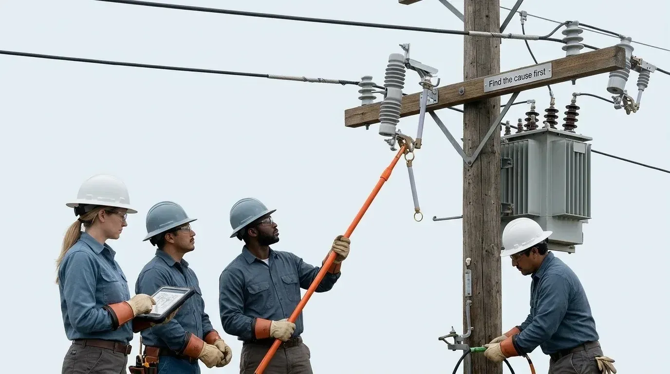
Never replace a blown link without finding the cause. A fuse that blew on a transformer fault will blow again, and re-energizing into a persistent short puts a crew, a pole and a transformer at risk. Treat replacement as a switching task, and follow your utility's procedure first, this guide second.
Before you touch anything
Confirm the job is authorized and that the switching order is in place. Inspect from the ground: which phases dropped, whether there is visible damage, tracking or burning on the transformer or bushings. Check the low-voltage side for a cause, such as a downed service or a failed customer installation. Wear the PPE the voltage class demands and use a properly rated hot stick that has been tested and cleaned.
Pulling the tube and fitting the new link
Isolate the transformer according to the switching procedure and confirm the open point on every phase.
Remove the dropped tube with the hot stick, lifting it off the hinge or the upper contact as the design allows.
Inspect the tube lining, ends and contacts for erosion, carbon tracking or deformation, and replace the tube if the lining is worn.
Fit the correct link, matching the rating and type (K or T) of the other phases, and set the tension as the manufacturer specifies.
Re-hang the tube and close it in firmly with a single positive motion, never slowly.
Closing in and confirming
Stand clear, close the tube fully and confirm the latch has seated. Check that all three phases are closed, then verify the secondary voltage and watch the transformer for abnormal noise. Record what was found and what was fitted.
Note: Closing a cutout onto a faulted transformer produces a severe arc at the contacts. If the cause of the first operation is unknown, do not re-energize on a hunch.
What Goes Wrong in the Field, and How Do You Avoid It?
Consider a typical rural feeder where one link blows every few months and the response each time is to fit a bigger one. Eventually the link is far too large for the transformer. A real internal fault then draws current that sits below the link's melting region, the fuse never operates, and the transformer fails with the oil heated past its limits. Oversizing is the quietest failure mode in this trade, because nothing seems wrong until the day it matters.
The reverse is just as common. An undersized link blows on inrush every time the line is re-energized after an outage, leaving customers out for no good reason. The practical check is to compare the link's curve with a realistic inrush figure for the transformer size, and to use a T link where cold-load pickup is routine.
Corroded contacts are the third. Salt, industrial deposits and thermal cycling raise contact resistance, which heats the link area, which ages the link, which then melts at a lower current than rated. Infrared scanning during routine patrols catches hot contacts early. Clean or replace the hardware, do not just swap the link.
Last, tubes that fail to drop. Causes include a stiff hinge, paint or debris on the latch, a bent mounting bracket and a worn lining that no longer gives the expected gas pressure. The tube must fall freely or the visible break is lost and the arc may not clear. Test the swing during maintenance and replace tubes on schedule.
FAQ
Why does my fuse link keep blowing when the transformer is energized?
Usually inrush current. A link sized too close to full-load current melts on the energizing surge. Check the multiplier used, consider a T link, and look for a real fault before changing size.
Can I mix K and T links on one three-phase bank?
No, avoid it. Different curves mean the phases clear at different times under the same fault, which invites single-phasing. Use one link type and rating across the bank.
Can I reuse a fuse tube after the link blows?
Often yes, if the lining is intact. Inspect for erosion, carbon tracking and distortion. A tube with a worn bore loses arc-extinguishing capacity and should be replaced.
How is a fuse cutout different from a circuit breaker?
A cutout is single-operation and replaced after tripping, while a breaker can reset. A cutout is simpler and cheaper but offers no adjustable settings and no reclosing.
Does a fuse cutout replace an overload relay?
No. It responds to current magnitude along a fixed curve and will not catch moderate sustained overload. Use load monitoring if thermal protection of the transformer is needed.
Summary
Size the link from the transformer's rated primary current with an allowance for inrush, choose the cutout body separately for voltage and fault level, and confirm both on the time-current curve. Before you re-energize after any operation, find the cause of the fault and verify the open point and the tube's free drop. For your next purchase, request the type test documentation for the exact cutout model and compare it to your feeder's fault level.