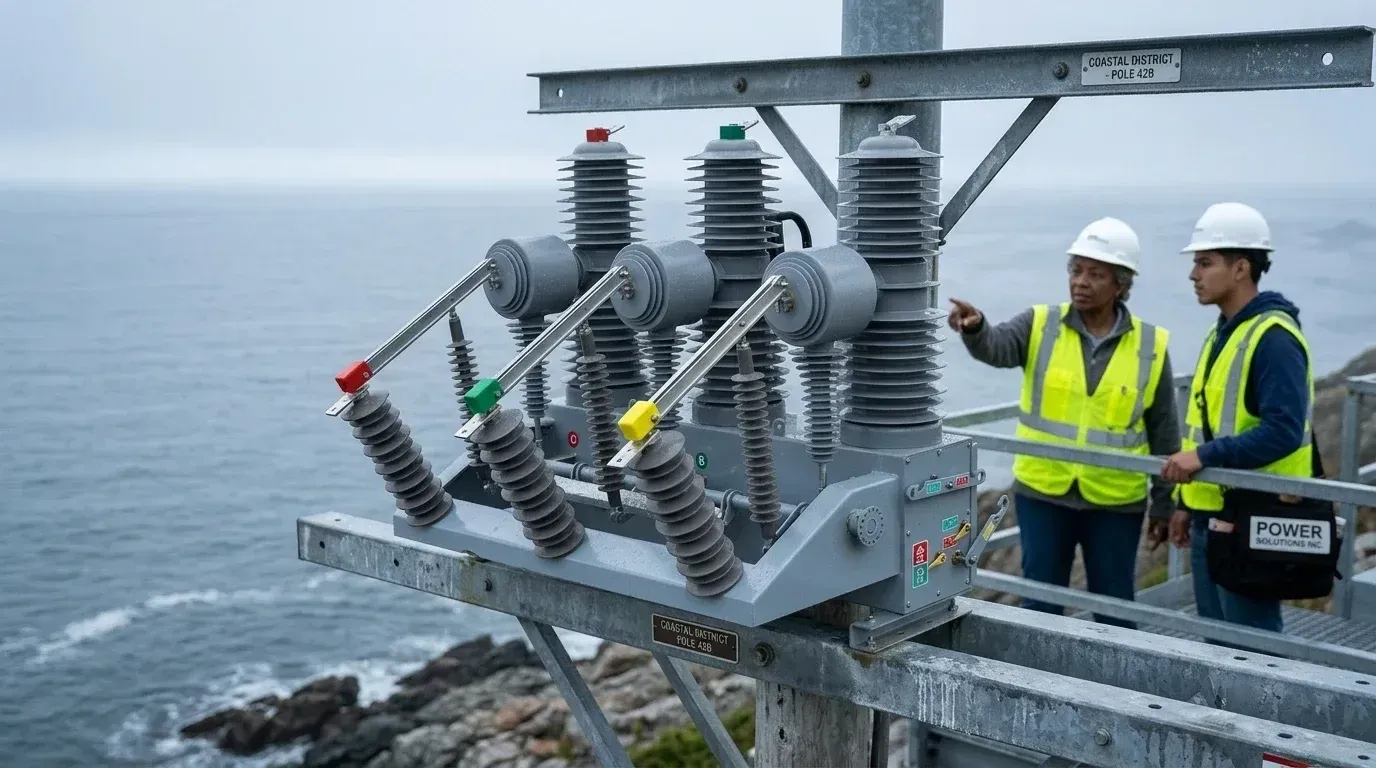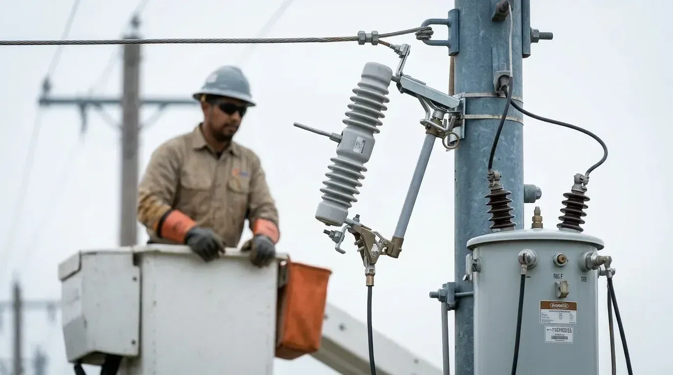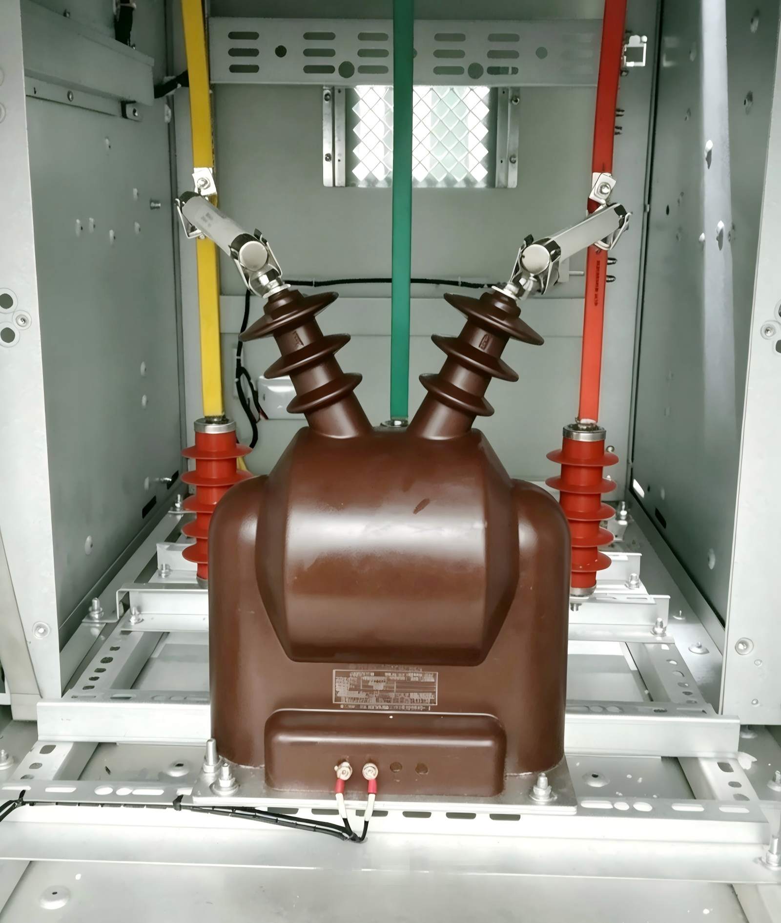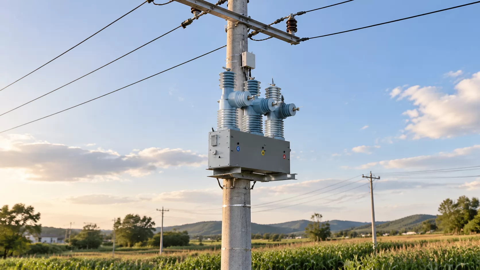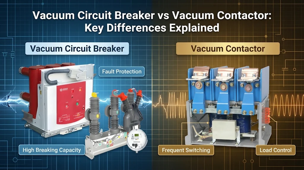
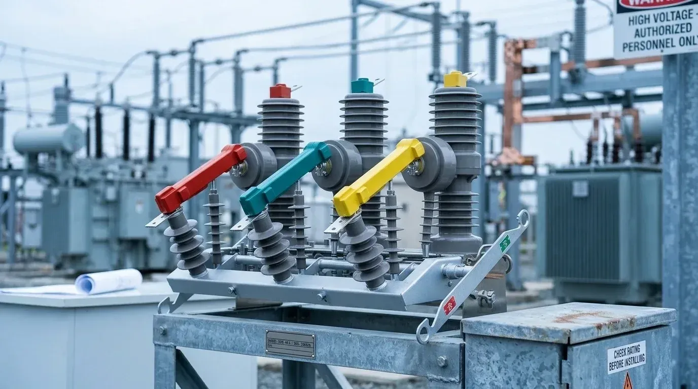
The question typically reaches the engineer in practical terms: which outdoor vacuum circuit breaker is appropriate for transformer protection at a given installation? The governing principle is that the breaker must first be rated for the prospective fault level at the point of installation, and only then for the characteristics of the transformer it protects. The selection process proceeds in four sequential phases: collection of site data; determination of ratings; definition of protection and enclosure requirements; and verification of applicable standards followed by preparation of the request for quotation (RFQ). The result is a complete technical specification that can be issued to suppliers for tender.
What Decides an Outdoor Vacuum Circuit Breaker for Transformer Protection?
Seven parameters decide an outdoor vacuum breaker for a distribution transformer, and they do not carry equal risk. Short-circuit breaking current comes first, because no relay setting or accessory can rescue an interrupter that is too small for the fault. The other six follow in order of what a mistake would cost you on site.
Specify breaking current above the prospective fault current at the installation point before you set anything else. That ranking shifts only when the utility fault level is low and well documented, in which case insulation and transient duty often become the harder calls.
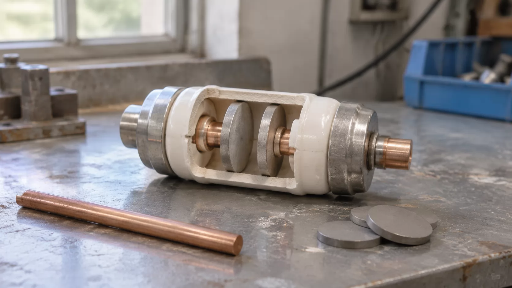
A vacuum circuit breaker (VCB) is a switching device that interrupts current inside a sealed vacuum interrupter, where the arc has no gas to sustain it and goes out at a natural current zero. Outdoors, that interrupter sits inside a housing that has to survive weather, dirt and years of temperature cycling. The ranking below puts the seven deciding parameters in order of consequence:
Rated short-circuit breaking current, set above the system fault current at the pole.
Rated voltage, matched to the transformer primary, with outdoor creepage for the site.
Rated current, sized from the transformer primary current plus a 20–25% margin.
Making capacity, able to withstand energizing inrush of up to 8–12 times rated current.
TRV duty, suited to faults on the transformer secondary side.
Relay coordination for instantaneous, overcurrent, zero-sequence and gas tripping.
Outdoor pole mounting that copes with temperature swings, condensation and dust.
Items five to seven are where transformer duty parts company with ordinary feeder switching. Most spec sheets handle the first four well; the last three are where tenders get vague.
The One Rating You Cannot Get Wrong
Breaking current is the largest fault current the breaker can interrupt and still remain serviceable. If the fault current at the pole exceeds it, the interrupter may fail to clear. The arc then keeps burning, the vacuum bottle can be damaged or rupture, and the fault has to be cleared by the next device upstream. That device is often a substation feeder breaker that takes a whole circuit down with it.
The rating has to be checked against the fault level at the installation point, not a general figure for the network. A pole close to a primary substation sees far more fault current than one at the end of a long rural line. And the figure is not fixed. When the utility adds a transformer, reinforces a line or ties in new generation, fault levels at existing points tend to rise. A breaker that was adequate on commissioning day can be under-rated a few years later with nothing on the pole having changed.
So ask for headroom. Pick the next standard breaking current value above the calculated fault level, and if the utility has published reinforcement plans, size to the future figure rather than today's.
Why Transformers Are a Special Load
Energizing a transformer drives its core toward saturation for a few cycles, producing an inrush current that, per the supplied engineering notes, can reach 8 to 12 times rated current. The breaker has to close into that without welding its contacts, and the relay has to ride through it without tripping. A feeder breaker spec rarely anticipates either.
Faults on the secondary side bring a second problem. The transformer's own inductance limits the fault current, which sounds benign, but it also produces a transient recovery voltage (TRV) that rises fast and high once the arc goes out. TRV is the voltage that appears across the open contacts in the first microseconds after interruption. If it climbs faster than the gap regains its dielectric strength, the arc restrikes.
The third is current chopping. Vacuum interrupters can force a small current to zero before its natural zero, typically at a few amperes with modern contact materials. When that current is the magnetizing current of an unloaded transformer, the energy trapped in the winding inductance turns into a voltage spike. Each of these three effects points to a specific line in your spec, which is why a generic feeder breaker template does not carry over.
Phase 1: Gather Site Data
The goal of this phase is simple: collect every input before any rating is chosen. Breakers get mis-specified less often through bad engineering than through a single number someone guessed, usually the fault level, and a single number like that can sit unnoticed in a spec for years. The steps are three, and the phase is finished when nothing in your rating sheet rests on an assumption.
The table maps each data item to its source and to the rating it ends up driving. Use it as the request list for the utility and the site team.
| DATA ITEM | WHERE TO GET IT | RATING IT DRIVES |
|---|---|---|
| Prospective fault current at the pole | Utility network study | Breaking current |
| Planned network reinforcement | Utility planning department | Breaking current headroom |
| Transformer kVA | Nameplate | Rated current, CT ratio |
| Primary voltage | Nameplate | Rated voltage |
| Impedance (%) | Nameplate or test report | Secondary fault level, relay settings |
| Pollution and humidity level | Site survey | Creepage distance, enclosure sealing |
| Altitude | Site survey | Insulation correction |
The utility rows usually take the longest to come back, so request them on day one and build the rest of the sheet while you wait.
Fault Level at the Pole
Ask the utility for the prospective three-phase short-circuit current at the exact installation point. A figure at the substation busbar overstates it for a distant pole, which costs you money, and a figure from a different feeder can understate it, which is a safety problem. Request the earth fault current as well, since zero-sequence protection depends on it.
Ask in writing whether reinforcement, new substations or generation connections are planned for that feeder. Note the answer and the date. If the utility declines to commit, record that too, because it justifies a higher breaking rating in the tender.
Transformer Nameplate Essentials
Record the kVA rating, the primary voltage (10 kV, 35 kV and so on), the vector group and the percentage impedance. Confirm the construction: an oil-immersed unit with a conservator usually carries a Buchholz relay, while a hermetically sealed tank typically uses a pressure relief device and a different trip contact. That one detail changes the protection wiring in Phase 3.
Impedance matters more than people expect. It sets the fault current a secondary-side short can push back through the primary, which feeds both the relay settings and the TRV discussion later.
Site Environment Survey
Log the daily temperature swing, condensation risk, dust or industrial pollution, salt from coastal air, and altitude. Night-time cooling after hot days is the condition that pulls moisture into enclosures, so note it explicitly rather than only recording minimum and maximum temperatures.
Altitude above roughly 1,000 m needs flagging, because IEC 62271-1 calls for an insulation correction above that level as thinner air reduces external dielectric strength. These entries become the creepage and sealing decisions in Phase 2.
Voltage and Creepage Ratings
Phase 2 turns site data into ratings, and outdoor VCB rating selection starts with voltage. Match the breaker's rated voltage to the transformer primary system. The rated voltage of switchgear is the highest system voltage it is designed for, so it sits above the nominal value: under IEC practice a 10 kV system normally takes 12 kV equipment, and a 35 kV system in China is usually served by 40.5 kV equipment.
If you buy for IEC-region networks outside China, the counterpart class is 33 kV nominal, and 33kV outdoor vacuum circuit breaker specifications are typically written around a 36 kV rated voltage. Do not assume a 36 kV unit can stand in for a 40.5 kV one on a 35 kV network. The insulation levels differ, and a utility inspector will check the nameplate against the system.
External insulation is the next check. Creepage distance is the shortest path along the surface of an insulator between conductive parts; dirt and moisture on that surface form a conducting film, and if the path is too short, flashover follows. IEC 60815 sets out how to classify site pollution severity and select a matching specific creepage distance, with requirements rising from very light to very heavy sites. Take the pollution class from your Phase 1 survey, apply the IEC 60815 method, and state the minimum creepage in millimetres in the spec rather than writing "suitable for outdoor use".
Bushing and post insulator material belongs here too. Silicone rubber housings shed water better than porcelain on dirty sites and tend to hold up well under pollution, but ask for UV ageing data if the site is high and sunny. For altitude above the IEC 62271-1 threshold, the supplier should show the corrected insulation level, not just the sea-level rating.
Vacuum Circuit Breaker Sizing for Distribution Transformer
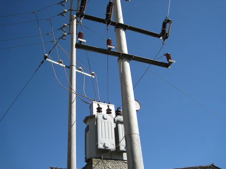
Start from the transformer, not from anything else on the pole. Primary rated current for a three-phase transformer is kVA divided by (√3 × primary kV). For a 1,000 kVA unit on a 10 kV system that gives roughly 57.7 A. The supplied engineering guidance adds a 20–25% margin so the breaker and its protection ride through inrush, which takes the design figure to about 69–72 A.
Do not size the breaker off the fuse it replaces or the cable feeding it. Fuse and cable ratings carry their own margins and history; stacking a breaker margin on top of them pushes CT ratios and relay pickups far above what the transformer needs, and small faults go undetected. Size off the transformer primary current.
Here is the part that surprises people the first time. Standard outdoor VCB frames usually start at 630 A rated current, so the continuous rating is almost never the limit for a distribution transformer. Where the 20–25% margin actually earns its keep is the current transformer ratio and the overcurrent pickup. A 630 A breaker with a 600/5 CT protecting a 57.7 A transformer has relays working at the bottom of their range, where accuracy drops. Specify the CT ratio from the margined transformer current, for example something in the region of 75/5 or 100/5 for the 1,000 kVA case, and confirm the CT will not saturate on the highest fault level from Phase 1.
For a 35 kV transformer of the same rating, primary current falls to roughly 16.5 A, so the CT question becomes sharper still. Low-ratio CTs at that voltage can be harder to source with adequate accuracy class, which is worth raising early with the supplier.
Breaking and Making Capacity
Breaking current comes back here as a hard number. Take the prospective fault current from Phase 1, include any planned growth, and choose the next standard value above it. IEC 62271-100 uses a series of preferred values such as 16 kA, 20 kA, 25 kA and 31.5 kA for medium-voltage breakers. Choosing the next step up typically costs little compared with replacing a breaker after a network upgrade.
Making capacity is the peak current the breaker can close onto and latch without damage. Under IEC 62271-100 the rated short-circuit making current is 2.5 times the rated breaking current for 50 Hz systems and 2.6 times for 60 Hz. A 20 kA breaker therefore carries a making rating of about 50 kA peak, which comfortably covers the inrush of a distribution transformer even at 8–12 times rated current.
Covered on paper, though, is not the whole story. Inrush recurs every time the transformer is energized, and frequent switching wears contacts and mechanisms. If the unit will be switched often, for seasonal loads or load shedding, ask for mechanical endurance class M2 and electrical endurance class E2 under IEC 62271-100, which are the higher endurance classes in that standard.
The table sets out each capacity parameter with its rule and the Phase 1 input it depends on.
| PARAMETER | SELECTION RULE | SOURCE INPUT |
|---|---|---|
| Rated breaking current | Next standard value above site fault level | Utility fault study |
| Breaking current headroom | Cover planned network reinforcement | Utility planning answer |
| Rated making current | 2.5× breaking at 50 Hz, 2.6× at 60 Hz | IEC 62271-100 |
| Inrush withstand | Above 8–12× transformer rated current | Transformer nameplate kVA |
| Endurance class | M2 and E2 for frequent switching | Expected switching duty |
In practice the breaking current row decides the frame; the others are confirmations that rarely change the selection but often expose a weak quote.
TRV and Chopping Control
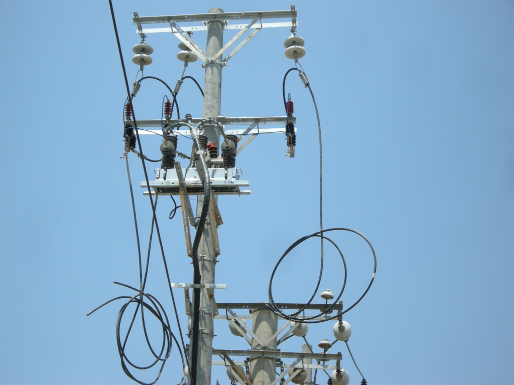
A short circuit on the transformer secondary is limited by the transformer's impedance, so the current through the primary breaker is modest compared with a line fault. The recovery voltage, however, is not. The inductance and small stray capacitance of the winding produce a TRV with a steep rate of rise, and the interrupter has to withstand it in the microseconds after current zero.
Specify an interrupter suited to transformer duty. Ask the supplier directly whether the breaker has been tested for transformer-limited fault conditions, and request the test record. IEC 62271-100 includes a low-current test duty, T10, with a demanding TRV, and IEEE C37.011 is the application guide that discusses transformer-limited faults. A breaker that only passed the high-current duties has not proven this case.
Chopping overvoltage is the second concern. When the breaker opens an unloaded or lightly loaded transformer, the magnetizing current may be chopped before its natural zero, and the energy in the winding appears as a voltage spike across the insulation. An RC snubber, a resistor and capacitor connected between phase and earth near the transformer terminals, absorbs that energy and slows the rate of voltage rise. The supplied guidance treats it as an addition to make where needed rather than a default. Surge arresters at the transformer remain standard practice either way; the snubber handles the steep front that arresters alone may not.
Phase 2 check: put each rating next to the Phase 1 data point that set it. Voltage traces to the nameplate, creepage to the pollution survey, current to kVA, breaking current to the utility study, TRV duty to the transformer impedance. Any rating with no line back to site data is a guess.
Phase 3 Relay Coordination
The goal of this phase is a breaker that trips for the right faults and stays closed for everything else. A transformer protection relay is the device that measures current, and in some cases receives trip contacts from the transformer itself, and sends the opening command to the breaker. Pole-mounted breakers are commonly paired with self-powered relays or controllers that draw energy from the CTs, so no auxiliary supply is needed at the pole.
The supplied guidance lists four functions to link to the breaker, set out below with what each catches.
| PROTECTION FUNCTION | FAULT IT DETECTS | TRIP ACTION |
|---|---|---|
| Instantaneous (50) | High-current fault at primary or bushings | Trip with no intentional delay |
| Overcurrent (51) | Secondary faults, sustained overload | Time-delayed trip on inverse curve |
| Zero-sequence (50N/51N) | Earth faults on primary side | Trip, delayed or instantaneous |
| Buchholz / gas | Internal winding or oil fault | Trip via interlock, block reclosing |
Instantaneous and gas tripping clear the dangerous faults fast; the overcurrent and earth-fault settings are where coordination effort goes.
Set the instantaneous pickup above the inrush current and above the through-fault current for a secondary short, so it only sees faults on the primary side. Grade the overcurrent protection settings against the low-voltage fuses or breakers downstream and the utility relay upstream, with a time margin between curves that is typically around 0.3–0.4 s. Inverse curve shapes are defined in IEC 60255-151.
One trap: many pole-mounted vacuum breakers are sold as reclosers with automatic reclosing enabled. For transformer protection, a gas trip or an instantaneous trip on an internal fault must block reclosing. Re-energizing a transformer with a winding fault is how a repairable failure becomes a tank fire.
Outdoor Duty and Mounting
Oil-immersed distribution transformers on poles call for a pole-mounted breaker built for exposure: a sealed tank, external bushings, and an operating mechanism that works through years of heat and cold. The supplied guidance names temperature swings, condensation and dust as the conditions to design for.
Condensation causes the quiet failures. Air inside the enclosure cools at night, moisture settles on the mechanism and secondary wiring, and corrosion builds up over months. Ask how the enclosure is sealed, whether it is gas-filled or solid-insulated, and what anti-condensation measures sit in the control cabinet, such as heaters or breathers. Request the IP rating of the mechanism and control box, and match the ambient temperature class to your Phase 1 log rather than accepting a default range.
Dust and salt affect both creepage and moving parts. Check that the manual operating handle and position indicator remain readable from ground level after years of grime, since linemen will rely on them for isolation.
Phase 3 check: compare the protection scheme and enclosure spec against the site survey line by line. If the survey recorded heavy pollution and the enclosure spec says "standard outdoor", the phase is not finished.
Standards and Type Tests
Phase 4 converts everything into a document a supplier can price. Cite standards by exact name so quotes can be compared on the same basis.
For IEC markets, IEC 62271-1 covers common specifications for high-voltage switchgear, including insulation, temperature rise and altitude correction. IEC 62271-100 covers alternating-current circuit breakers specifically: breaking and making ratings, test duties and endurance classes. IEC 60815 governs insulator selection for polluted conditions, and IEC 60255 covers measuring relays and protection equipment. For North American and other ANSI markets, cite IEEE C37.04 for ratings structure, IEEE C37.06 for preferred ratings, and IEEE C37.09 for test procedures.
Ask for type test reports issued by an accredited, independent laboratory, covering the exact rating and interrupter you are buying. A manufacturer's declaration of conformity is not a test report. Check that the report names the same breaking current, rated voltage and interrupter model as the quote; a report for a sister model at a different rating does not transfer. If you are comparing a Weisho Electric offer against another supplier, lay the type test reports side by side by test duty, including the low-current T10 duty, before comparing price.
Supplier and RFQ Checklist
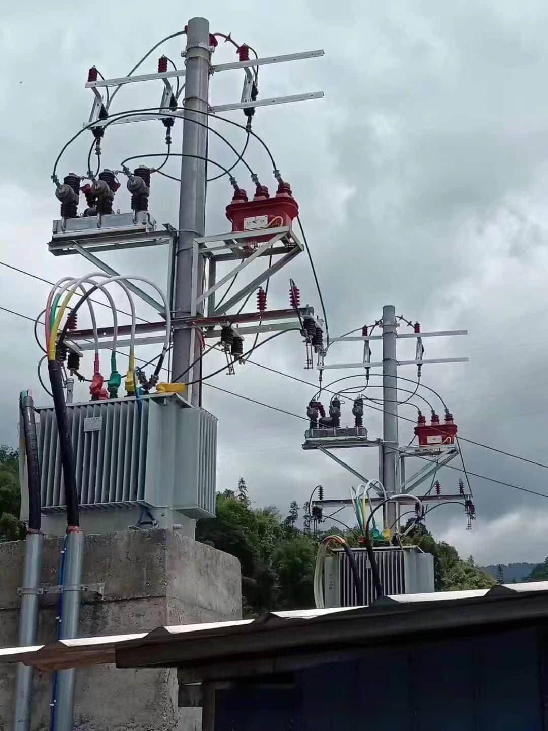
Quotes for outdoor breakers often look alike on the summary page and differ underneath. Use this short decision path when comparing them:
If two quotes match on ratings, then favour the one whose type test reports cover the exact quoted model.
If the supplier buys interrupters from a third party, then ask for the interrupter maker and its own test data.
If you already run a relay platform, then confirm the breaker's trip coil and CT outputs suit it.
If the site is remote, then weigh spare mechanisms and interrupters above a small price difference.
If the lead time overlaps your energization date, then ask for a factory test date in writing.
The RFQ itself should leave the supplier nothing to assume. When you send it, whether to Weisho Electric or any other manufacturer, attach the full data set and state how delivery will be accepted:
Attach the utility fault level at the installation point and any reinforcement notes.
Include the transformer nameplate: kVA, primary voltage, impedance and construction.
State rated voltage, breaking current, minimum creepage and altitude.
Specify CT ratio, relay functions and the reclose-blocking requirement.
Request type test reports and routine test certificates per IEC 62271-100 or IEEE C37.09.
Check nameplate data against the purchase order at delivery.
Witness or review routine tests, including insulation and contact resistance.
Inspect seals, bushings and the control cabinet for transit damage before signing.
A supplier who returns questions on this list is reading it properly; one who returns only a price usually has not.
FAQ
How to select a vacuum circuit breaker for a transformer without a fault level?
Assume the worst case. Use the substation busbar fault level or the upstream breaker's rating as a conservative ceiling, then keep pressing the utility for a point-specific figure.
Can one breaker rating cover both 10kV and 35kV transformers?
No. A 10 kV system typically uses 12 kV equipment, while 35 kV systems need 40.5 kV or similar insulation, so separate ratings are required.
Is a 20–25% current margin enough for frequent switching?
Yes, for current. Frequent switching is a wear issue, so also specify endurance classes M2 and E2 under IEC 62271-100.
When is an RC snubber necessary rather than optional?
Mostly when unloaded transformers are switched often. Short cable runs, dry-type or sensitive windings and repeated magnetizing-current interruption raise chopping overvoltage risk enough to justify one.
Does a pole-mounted VCB need a separate relay?
Usually yes, though often integrated. Many units ship with a self-powered controller; confirm it offers instantaneous, overcurrent, earth-fault, and gas trip inputs with reclose blocking.
Once quotes come back, the next question is usually about commissioning: which settings to apply on day one, how to verify CT polarity, and how to test the gas trip without draining oil. That is worth drafting before the breaker arrives on site.