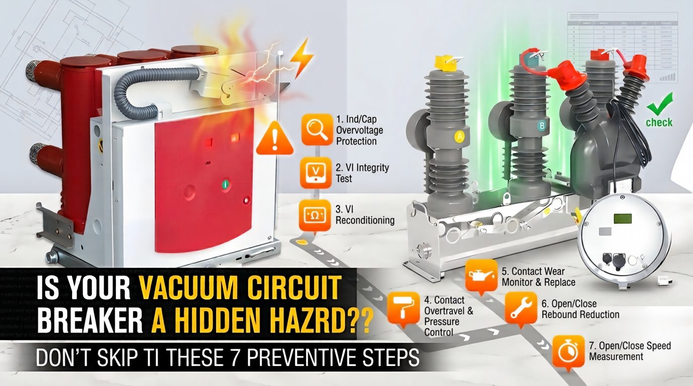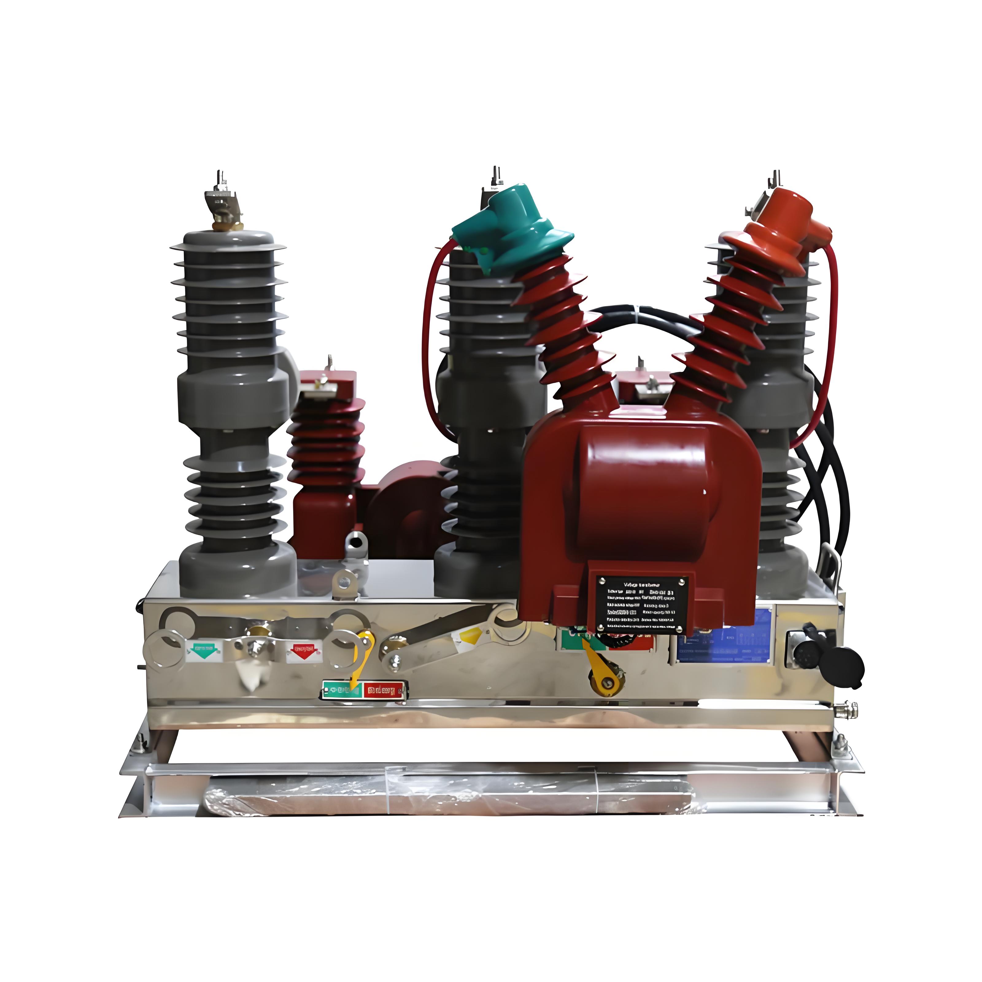
Vacuum circuit breaker reliability is rarely lost in one dramatic moment. In actual substations, industrial plants, rail systems, and distribution networks, it is usually eroded by small hidden defects: declining vacuum degree inside the interrupter, trip circuit abnormalities, linkage wear, switch drift, excessive contact bounce, or an energy storage mechanism that no longer behaves consistently.
This article is written for maintenance engineers, plant managers, switchgear specialists, and service teams who need a practical, field-oriented guide rather than theory alone. It focuses on vacuum circuit breaker failure analysis, the most frequent fault patterns, root causes, test methods, and corrective actions that directly improve operating reliability.
The core maintenance lesson is simple: many of the most dangerous faults in an Indoor vacuum circuit breaker or an Outdoor Vacuum Circuit Breaker are not obvious during casual visual inspection. Some of them remain hidden until a close failure, trip refusal, or interruption failure happens under fault current.
That is why experienced teams do not rely on appearance. They rely on instruments, operating records, low-voltage functional tests, characteristic analyzers, and disciplined troubleshooting workflows.
In field projects, service teams that shifted from “repair after failure” to “periodic targeted testing” consistently reduced severe breaker events. On several medium-voltage fleets in Asia-based industrial facilities, maintenance records commonly show that more than half of serious breaker defects are discovered during planned outage testing rather than after visible malfunction.
This is also where manufacturers and technical partners matter. In practical retrofit and replacement planning, many operators prefer solutions with simpler mechanical transmission paths and stronger consistency. In projects where lifecycle risk reduction is the priority, experienced suppliers such as Weisho Electric are often considered because maintenance teams increasingly value design stability, replacement compatibility, and test support rather than only initial purchase price.

Why Vacuum Circuit Breaker Fault Analysis Matters
A vacuum circuit breaker is expected to do two things without hesitation: close when commanded and trip when required. If either action fails, the consequences can include process shutdown, transformer stress, cable damage, busbar faults, protection miscoordination, and in severe cases, equipment rupture.
The problem is that many common vacuum circuit breaker faults do not announce themselves clearly. A breaker may look normal, show no external damage, and still have a degraded interrupter, a weakened trip path, or a hidden mechanical timing defect.
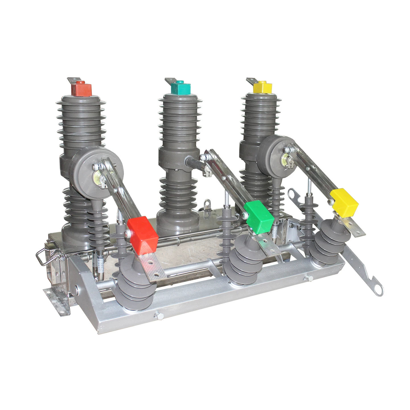
For an Indoor vacuum circuit breaker, hidden defects often develop through mechanical aging, coil circuit problems, switchgear compartment constraints, and overlooked periodic testing. For an Outdoor Vacuum Circuit Breaker, the same internal faults are compounded by humidity, contamination, corrosion, UV aging, enclosure sealing issues, and larger temperature swings.
From an operations standpoint, fault analysis matters because breaker failures are not isolated events. One breaker refusing to trip can escalate a feeder fault into upstream breaker operation, wider outage scope, and loss of selectivity. One breaker refusing to close can stop production lines, delay switching plans, or disrupt automatic transfer schemes.
In utility and industrial service records, trip refusal is consistently treated as a high-severity event. The reason is straightforward: a close refusal causes an inability to energize; a trip refusal can allow fault current to persist until another device clears it, often with much greater damage.
What Makes Common Vacuum Circuit Breaker Faults Hard to Detect
The hardest part of vacuum interrupter troubleshooting is that the fault may sit in three different layers at the same time: the primary interruption unit, the secondary control circuit, and the operating mechanism.
Vacuum loss in an interrupter is highly concealed. There is typically no practical online monitoring signal in most installed fleets. The breaker can remain apparently functional until the vacuum degree falls far enough to reduce interruption performance or insulation strength.
Secondary circuit issues are also deceptive. A loose terminal, blown fuse, weak DC supply, oxidized auxiliary contact, or partially damaged coil can produce intermittent close or trip failures that appear random unless measured under realistic conditions.
Mechanical wear creates another level of uncertainty. Excessive linkage clearance, dry pivots, worn pins, crank arm wear, travel switch drift, and dead-point deviation may not stop operation immediately. Instead, they first show up as slower timing, worse simultaneity, bigger bounce, or occasional refusal under low voltage or high duty.
This combination explains why many vacuum circuit breaker maintenance issues survive routine visual checks. Without vacuum testing instruments, breaker characteristic analyzers, continuity testing, coil resistance checks, and undervoltage operation tests, the hidden defect remains hidden.
Fault Map of Vacuum Circuit Breakers at a Glance
A useful maintenance strategy begins with a fault map. Not every defect has the same visibility, urgency, or first inspection point.
Table: Common Vacuum Circuit Breaker Faults, Symptoms, Risks, and First Checks
| Fault Type | Visible Symptom | Hidden Signal | Likely Cause | Operational Risk | Recommended First Action |
|---|---|---|---|---|---|
| Vacuum loss in interrupter | Often none | Abnormal vacuum test result, poor interruption margin | Bellows leak, interrupter body leak, split-type linkage stress | High to critical | Perform offline vacuum degree test |
| Close refusal | Breaker will not close | Coil not energized, control mode mismatch, mechanism drag | Line fault, operator error, power loss, mechanical sticking | Medium to high | First rule out line/load fault |
| Trip refusal | Breaker remains closed under trip command | Low voltage weakness, coil circuit open, trip rod jam | Broken trip circuit, bad coil, low DC, deformed rod | Critical | Isolate safely and verify trip circuit continuity |
| Energy storage circuit fault | Motor runs continuously or charging incomplete | Travel switch drift or damaged switch | Misaligned or faulty limit/travel switch | High | Inspect switch position and contact state |
| Non-simultaneity | No obvious visible symptom | Characteristic test shows phase timing deviation | Mechanical aging, long split transmission | Medium to high | Run breaker characteristic analyzer test |
| Excessive contact bounce | Usually invisible | Bounce time exceeds standard | Worn pins, crank arms, low spring preload, dead-point drift | Medium to high | Perform timing and travel analysis |
| Increased DC circuit resistance | Heating or abnormal conduction performance | Resistance trend rising | Contact gap or overtravel out of adjustment | Medium | Check contact opening distance and overtravel |
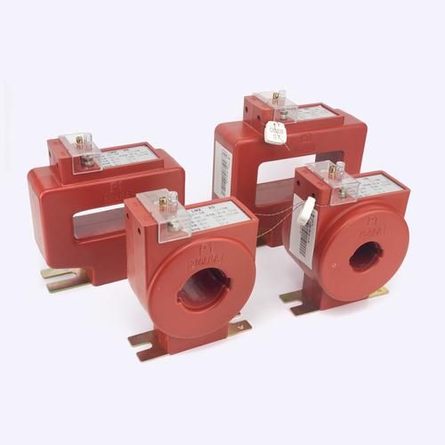
| CT surface discharge | Discharge marks, odor, sound | Insulation contamination or moisture path | Surface pollution, humidity, insulation degradation | Medium to high | Inspect and treat insulation surface immediately |
Vacuum Interrupter Vacuum Loss: The Most Critical Hidden Failure
Among all causes of vacuum circuit breaker malfunction, vacuum loss inside the interrupter is one of the most dangerous because it is both hidden and fundamental. The interrupter is the heart of the breaker. If vacuum integrity is compromised, interruption performance and insulation strength are compromised with it.
Most installed breakers do not provide direct online vacuum degree monitoring. As a result, the defect may stay unnoticed until periodic instrument testing, abnormal interruption behavior, insulation failure, or a severe fault event exposes it.
When vacuum degree falls below acceptable condition, dielectric recovery weakens. Arc extinction capability decreases. Under fault current, the interrupter may fail to interrupt properly, and in severe cases, rupture or explode.
Main Causes of Vacuum Loss in Vacuum Interrupters
Field investigations repeatedly point to three major causes.
Bellows leakage: repeated mechanical operation can fatigue the bellows, especially where alignment and stroke settings are poor.
Interrupter body leak points: manufacturing defects, aging seals, or damage at joints can gradually destroy vacuum tightness.
Unreasonable split-type linkage parameters: in split-type designs, poor parameter matching can impose extra stress on the interrupter and bellows, accelerating sealing failure.
This third factor is often underestimated. Long transmission distance and imperfect linkage geometry may not fail immediately, but over time they increase mechanical stress concentration and worsen consistency.
Typical Symptoms and Consequences of Low Vacuum Degree
The most frustrating symptom is often no visible symptom at all. That is why periodic testing is indispensable.
When symptoms do appear, they may include reduced breaking performance, insulation deterioration, abnormal operating sound during switching, failure to interrupt fault current, or evidence of internal distress after a fault event. In severe conditions, interrupter rupture is possible.
In practical maintenance reports, low vacuum degree also correlates with abnormal dielectric withstand results and unexplained interruption concerns during post-fault review.
Recommended Testing and Corrective Actions
The correct approach is instrument-based testing during planned outage. A dedicated vacuum tester or approved interrupter condition assessment method should be used according to manufacturer and maintenance standards.
If the measured value exceeds the allowable limit, the interrupter must be replaced. There is no credible field shortcut for restoring lost vacuum.
After replacement, the job is not finished. The following parameters must be rechecked:
Contact travel
Opening and closing timing
Phase simultaneity
Contact bounce
Overtravel
Mechanical linkage alignment
This is a critical practical point. A new interrupter installed into a poorly adjusted mechanism can create a second fault immediately.
Table: Vacuum Degree Test Results and Action Thresholds
| Example Test Condition | Assessment | Operational Meaning | Maintenance Decision |
|---|---|---|---|
| Within manufacturer acceptance range | Acceptable | Interrupter condition normal | Return to service after routine verification |
| Near warning threshold, trend worsening | Warning | Latent vacuum degradation suspected | Shorten retest interval and assess replacement plan |
| Beyond maintenance alarm limit | Critical | Insufficient interruption margin | Replace interrupter immediately |
| Fails withstand/condition test clearly | Severe critical | High interruption and insulation failure risk | Do not re-energize; replace and retest complete breaker characteristics |
Exact thresholds vary by voltage class, interrupter design, and manufacturer guidance. Maintenance crews should never substitute generic assumptions for the specified acceptance criteria of the installed model.
Closing Failure: Why Vacuum Circuit Breakers Refuse to Close
Close refusal is one of the most common field complaints, but troubleshooting must be disciplined. Randomly forcing repeated close attempts is a mistake. It wastes time, can damage the mechanism, and may attempt to energize into a real downstream fault.
The four major categories are consistent across many fleets:
Fault on the line or load side
Human operating error or control mode issue
Closing power supply or secondary circuit abnormality
Mechanical sticking in the operating mechanism
The fastest diagnostic sequence starts by distinguishing external system fault from breaker self-fault.
Fault on the Line or Load Side
This should always be ruled out first. If the feeder, cable, transformer, motor, or downstream equipment is faulted, protective logic or interlocks may intentionally block closing.
In actual substations, repeated unsuccessful close attempts sometimes occur because teams focus on the breaker and forget that the breaker may be acting correctly by refusing to energize a faulted circuit.
Review protection indications, SCADA alarms, fault records, relay targets, insulation data, and line condition before deeper breaker disassembly.
Human Operating Errors and Control Mode Issues
This category is more common than many teams like to admit. It includes:
Local/remote mode mismatch
Interlock misunderstanding
Failure to reset after previous operation
Incorrect sequence execution
Incomplete spring charging confirmation
On mixed old-and-new switchgear lineups, operators can also misread indicator states or assume a remote close path is active when the breaker is in local control only.
Closing Power Supply and Secondary Circuit Abnormalities
If the external circuit is healthy and operating mode is correct, attention moves to the control power and closing circuit.
Common issues include DC control power loss, fuse failure, loose terminals, oxidized contacts, broken wiring, defective auxiliary relay, and abnormal closing coil circuit conditions. A close coil may not energize at all, or it may energize weakly because of voltage drop.
Voltage should be checked under command condition, not just at idle. Some faults only appear when the circuit is loaded.
Mechanical Sticking in the Operating Mechanism
When electrical checks are normal but the breaker still refuses to close, the mechanism must be examined. Typical causes include linkage jam, poor lubrication, excessive clearance, misadjustment, worn transmission parts, and latch problems.
In older split-type breakers, long mechanical transmission paths increase the chance of accumulated play and inconsistent operation. This is one reason many users now prioritize integrated designs in modernization planning.
Table: Fast Diagnostic Sequence for Close Refusal
| Step Order | Inspection Item | Tool Needed | Expected Finding | Decision Point |
|---|---|---|---|---|
| 1 | Check line/load fault indication | Protection records, relay panel, test meter | No external fault lockout | If external fault exists, stop breaker-focused troubleshooting |
| 2 | Verify local/remote mode and interlock status | Panel indication, operation logic review | Correct mode and reset state | If mismatch exists, correct operating condition |
| 3 | Measure control power during close command | Multimeter | Voltage within acceptable range | If low or absent, repair supply path |
| 4 | Inspect fuse, terminals, close coil circuit | Continuity meter, resistance meter | Normal continuity and resistance | If abnormal, repair or replace components |
| 5 | Check mechanism and linkage movement | Visual inspection, manual operation tools | Smooth movement, no jam | If sticking exists, adjust/lubricate/replace parts |
Opening Failure: Why Vacuum Circuit Breakers Refuse to Trip
Trip refusal is a high-severity defect because it can amplify an otherwise manageable fault into a wider accident. If the breaker does not open when protection commands it to trip, fault current continues to flow until another device clears it or equipment fails.
This is why trip refusal receives stricter preventive attention than close refusal in serious maintenance programs.
Broken Trip Circuit or Trip Coil Fault
One common root cause is an open or degraded trip path. This includes broken wiring, loose terminals, burnt trip coil, poor contact condition, damaged auxiliary contact, or abnormal coil resistance.
During outage inspection, trip coil resistance should be measured and compared with historical records or manufacturer data. A resistance value drifting significantly from baseline can reveal partial winding damage even before total failure.
For example, in a 12 kV industrial switchgear fleet reviewed after nuisance events, two breakers with intermittent trip abnormalities showed trip coil resistance about 18% above fleet average. Post-replacement testing eliminated the issue.
Low Control Voltage and Energy Release Failure
Low DC voltage is a classic hidden trigger. Under normal calm conditions, the breaker may still appear functional. Under colder temperatures, simultaneous control loads, or dirty contacts, the available energy becomes insufficient for reliable tripping.
That is why measuring static battery voltage alone is not enough. You need to know what voltage reaches the trip coil at the moment of operation.
In several maintenance cases, systems with nominal 220 V DC control power dropped below effective operation threshold under command because of aged batteries, loose return connections, or high-resistance fuse holders.
Deformed or Jammed Trip Rod
A practical field issue seen in some mechanisms is trip rod deformation, especially where copper rods have been used and repeated mechanical stress or improper alignment has caused bending or sticking.
The maintenance recommendation is straightforward: if copper trip rods show deformation tendency, replace them with steel parts of approved specification. This is not cosmetic improvement; it directly improves mechanical integrity and trip reliability.
Low-Voltage Open-Close Testing as a Preventive Measure
Low-voltage open-close testing is one of the most useful preventive tools because it exposes weak margins that normal-voltage checks may miss. A breaker that trips correctly only at ideal voltage is already unreliable.
Undervoltage functional testing can reveal:
Marginal trip coil performance
Excess friction in the mechanism
Weak release action
Trip rod sticking
Poor terminal or contact condition
Maintenance teams that routinely perform low-voltage open-close tests usually find latent defects earlier and with less downtime than teams relying on full-voltage functional checks only.
Table: Opening Failure Causes, Inspection Method, and Remedy
| Symptom | Root Cause | Inspection Method | Corrective Action |
|---|---|---|---|
| No trip action at all | Open trip circuit | Continuity check, terminal inspection | Repair wiring, tighten or replace terminals |
| Trip coil does not actuate | Burnt or damaged trip coil | Measure coil resistance, insulation check | Replace trip coil |
| Intermittent trip refusal | Low control voltage | Voltage measurement during operation | Restore DC supply integrity, battery and contact path correction |
| Trip command present but mechanism does not release | Jammed or deformed trip rod | Mechanical inspection, manual movement check | Replace rod, preferably with steel upgrade where applicable |
| Trips at normal voltage only | Weak mechanism margin | Low-voltage open-close test | Correct friction, alignment, coil path, and worn parts |
Spring Operating Mechanism Energy Storage Circuit Faults
Spring mechanism problems are common in medium-voltage breakers and are often identified through two typical field symptoms: the energy storage motor keeps running continuously, or the breaker cannot complete charging to the correct stored-energy position.
This is not a minor annoyance. If the breaker cannot store and hold energy properly, it may fail to reclose, fail to complete the next operation, or behave unpredictably in switching sequences.
Travel Switch Misalignment or Damage
The most frequent root cause is travel switch position drift or travel switch failure. When the switch no longer changes state at the correct point, the motor may continue running or stop too early.
Position drift can occur because of vibration, mechanical wear, loose mounting, or previous incomplete adjustment during maintenance. Switch damage may include contact welding, wear, contamination, or internal failure.
Why Energy Storage Failure Can Trigger Upstream Trips
An incompletely charged spring mechanism may leave the breaker unable to perform the next demanded operation. In distribution systems, this can interfere with reclosing logic or selective protection behavior.
If a feeder breaker fails to reclose or fails to operate correctly during a downstream event, an upstream device may trip instead. This causes wider outage scope and creates the impression of a “protection problem” when the real root cause is a charging mechanism defect.
On-Site Repair and Functional Verification
The direct repair action is usually to adjust the travel switch position or replace the damaged switch. But field repair must not end there.
After correction, repeated open-close and charging verification should be performed on site. The aim is to confirm that the motor stops at the correct position, charging completes reliably, and no intermittent drift remains.
Experienced maintenance crews usually cycle the mechanism several times after repair rather than accepting one successful operation as proof.
Table: Energy Storage Circuit Fault Symptoms and Fixes
| Symptom | Likely Cause | Verification Method | Repair Action | Test-After-Repair Requirement |
|---|---|---|---|---|
| Motor runs continuously | Travel switch position drift | Check switch actuation point | Adjust switch position | Repeat charging cycle verification |
| Motor runs continuously | Travel switch damaged | Continuity/function test | Replace switch | Multiple charge-stop cycles |
| Charging incomplete | Switch stops motor early | Observe stop point and mechanism status | Readjust switch or linkage | Open-close functional test |
| Intermittent charging abnormality | Loose mounting or worn actuation part | Mechanical inspection | Tighten or replace worn component | Repetition test under actual control power |
Out-of-Synchronism and Excessive Contact Bounce: The Hidden Mechanical Defects
Some of the most damaging defects are not dramatic enough to trigger immediate operational alarm. They quietly shorten breaker life.
Out-of-synchronism between phases and excessive contact bounce are classic hidden mechanical faults. They usually require a breaker characteristic analyzer for detection. Without instrument testing, these problems are easily missed.
Root Causes of Non-Simultaneity and Excessive Bounce
Common root causes include:
Mechanical aging
Long transmission distance in split-type breakers
Worn shaft pins
Worn crank arms
Reduced contact spring preload
Dead-point deviation in the mechanism
Linkage clearance growth
These faults often develop gradually. Timing spread may increase little by little over years until the breaker falls outside acceptable characteristic limits.
Performance Impact on Indoor and Outdoor Vacuum Circuit Breakers
For both Indoor vacuum circuit breaker and Outdoor Vacuum Circuit Breaker applications, non-simultaneity and excessive bounce increase arc time, thermal stress, contact wear, and insulation stress.
In outdoor service, contamination and environmental aging may further worsen the effect of mechanical inconsistency. In indoor service, high operation frequency and compact compartment design often make wear progression harder to notice until characteristic testing reveals it.
The practical result is reduced reliability, lower interruption consistency, and shorter service life.
Preferred Retrofit Strategy
Where lifecycle reliability is a key concern, integrated breaker designs are generally preferred over split-type structures. The reason is mechanical simplicity: fewer transmission variables, shorter force path, and usually better timing consistency over long service periods.
For facilities preparing medium-voltage fleet modernization, this is a procurement issue as much as a maintenance issue. Buying a breaker that is harder to keep in tolerance creates years of avoidable service cost.
In real retrofit discussions, operators increasingly ask suppliers not only for rated parameters, but also for characteristic stability, spares continuity, and test documentation. This is one reason brands like Weisho Electric can stand out when the evaluation is based on maintainability and long-term operating consistency rather than on brochure specifications alone.
Table: Characteristic Test Parameters to Track Periodically
| Parameter | Why It Matters | Typical Alarm Logic | Maintenance Response |
|---|---|---|---|
| Opening time | Indicates release and mechanism speed | Deviation from baseline or manufacturer limit | Inspect trip path and friction points |
| Closing time | Reflects stored energy release quality | Slower than reference trend | Inspect charging state and mechanism drag |
| Phase simultaneity | Ensures balanced interruption and closing | Interphase timing spread exceeds limit | Adjust linkage or investigate wear |
| Travel | Confirms contact motion is correct | Out of specified range | Re-adjust interrupter/mechanism setup |
| Overtravel | Influences contact pressure and electrical performance | Low or high beyond tolerance | Correct mechanical setting |
| Bounce time | Affects contact wear and closing quality | Exceeds standard or trend worsens | Increase preload, replace worn linkage parts, optimize dead point |
Other Common Vacuum Circuit Breaker Maintenance Issues
Field maintenance logs contain many recurring auxiliary faults that are not as catastrophic as trip refusal but still deserve prompt correction. Left alone, these small defects often evolve into larger failures.
Energy Storage Motor Does Not Stop
This problem is most directly linked to travel switch position correction or travel switch replacement. Teams should not waste time overcomplicating the diagnosis when the symptom clearly points to stop-position feedback failure.
Increased DC Circuit Resistance
If the DC circuit resistance becomes too high, one practical cause is improper arc chamber contact gap and overtravel adjustment. This should be checked carefully after interrupter replacement or major mechanism work.
A rising resistance trend is not just a number problem. It usually means more heat, poorer conduction performance, and reduced operating margin.
Closing Bounce Exceeds Standard
When closing bounce exceeds the allowable value, several practical corrections are available:
Increase contact spring preload
Replace worn shaft pins
Replace worn crank arms
Optimize mechanism dead-point position
Maintenance crews should avoid “partial guessing.” Bounce problems usually require characteristic measurement before and after adjustment to confirm real improvement.
CT Surface Discharge and Interrupter Failure to Break Current
These are two very different problems and should not be mixed.
CT surface discharge is generally an insulation surface problem caused by contamination, humidity, cracking, or local aging. The remedy is targeted insulation treatment: cleaning, drying, sealing, replacing damaged insulation components, and correcting environmental ingress.
Interrupter failure to break current, by contrast, is often a severe internal problem. In many practical cases, the root cause is vacuum deterioration leading to insulation failure inside the interrupter. If that condition is confirmed, the interrupter should be treated as unserviceable and replaced.
Table: Auxiliary Faults and Targeted Corrective Actions
| Symptom | Probable Cause | Urgency | Maintenance Recommendation |
|---|---|---|---|
| Energy storage motor keeps running | Travel switch position error or switch failure | High | Adjust or replace travel switch, then cycle test |
| DC resistance rises | Contact gap/overtravel out of adjustment | Medium | Readjust interrupter contact parameters |
| Closing bounce too large | Low preload, worn pins, worn crank arm, dead-point deviation | Medium to high | Adjust preload and replace worn transmission parts |
| CT surface discharge | Contamination, moisture, insulation deterioration | High | Clean, dry, inspect, repair or replace insulation parts |
| Interrupter cannot break current | Vacuum deterioration causing insulation failure | Critical | Remove from service and replace interrupter |
Real-World Failure Analysis Cases and Field Data
Authoritative maintenance guidance becomes more credible when it reflects how failures actually appear in service. The following examples are based on practical patterns repeatedly seen in medium-voltage fleets.
Case 1: Hidden Vacuum Loss Found During Periodic Instrument Testing
A 12 kV indoor feeder breaker in industrial service had no visible external abnormality. Operation count was moderate, around 2,800 mechanical operations over 9 years. Operators reported no recent nuisance behavior.
During a scheduled outage, offline vacuum condition testing showed one phase interrupter beyond the maintenance alarm threshold. Follow-up characteristic checks also showed the phase travel slightly outside baseline.
The interrupter was replaced, and travel, simultaneity, and bounce were retested. Post-repair values returned to standard. Without the planned instrument test, this breaker would likely have remained in service with a hidden interruption risk.
Case 2: Trip Refusal Caused by Deformed Trip Rod Under Low Voltage
An industrial distribution breaker occasionally failed to trip during simulated control checks, but only under reduced DC voltage conditions. At nominal control voltage, the fault was intermittent and easy to miss.
Low-voltage open-close testing reproduced the problem reliably. Inspection found the copper trip rod slightly deformed and sticking under marginal force conditions.
The rod was replaced with an approved steel component. After repair, the breaker passed repeated undervoltage trip tests and returned to stable service.
Case 3: Continuous Energy Storage Motor Operation Due to Travel Switch Drift
An outdoor pole-mounted breaker showed a charging motor that kept running after spring charging should have completed. The breaker had been exposed to vibration and seasonal temperature variation for several years.
Inspection confirmed travel switch position drift. The switch was readjusted, mounting tightened, and the charging cycle retested several times. Normal stop behavior returned, and no further abnormal charging was reported in subsequent follow-up inspection.
Table: Example Field Cases, Root Cause, Downtime Impact, and Final Resolution
| Breaker Type | Service Age | Detected Fault | Root Cause | Repair Time | Downtime Impact | Post-Repair Outcome |
|---|---|---|---|---|---|---|
| 12 kV Indoor vacuum circuit breaker | 9 years | Hidden vacuum degradation | Interrupter leak | 1 shift | Planned outage only | Interrupter replaced, characteristics restored |
| 12 kV feeder breaker | 7 years | Trip refusal under low voltage | Deformed copper trip rod | 6 hours | Prevented repeat protection failure | Steel rod retrofit solved issue |
| Outdoor Vacuum Circuit Breaker | 6 years | Motor runs continuously | Travel switch drift | 3 hours | Minor outage, major risk avoided | Switch adjusted, charging normalized |
These cases reflect a larger industry truth: the most valuable maintenance work often prevents a failure that the operation team never gets to see. That is success, not a lack of evidence.
Step-by-Step Troubleshooting Workflow for Vacuum Interrupter Troubleshooting
When a breaker fault appears, a structured sequence saves time and reduces wrong replacement decisions. Good troubleshooting is not just about technical skill. It is about maintaining order under pressure.
Step 1: Confirm Fault Phenomenon and Safety Isolation
Start with the operation record, event list, indicator lights, panel status, and operator report. Confirm whether the event is close refusal, trip refusal, charging abnormality, timing defect, insulation issue, or suspected vacuum condition problem.
Then complete lockout, isolation, discharge, and outage preparation according to safety procedures. No breaker diagnosis is worth bypassing safe isolation.
Step 2: Distinguish Primary Circuit Fault from Breaker Self-Fault
Before opening the breaker mechanism, determine whether the primary system itself is faulted. Check downstream line, cable, transformer, motor, or bus condition and review protection operation.
This step prevents one of the most common errors in vacuum circuit breaker failure analysis: treating a legitimate protective lockout as a breaker defect.
Step 3: Check Control Power, Secondary Circuit, and Coil Health
Measure control voltage under operation command. Check continuity through trip and close circuits. Measure coil resistance. Inspect fuses, terminals, relay contacts, auxiliary contacts, and connectors.
This stage quickly narrows many electrical causes of vacuum circuit breaker malfunction.
Step 4: Inspect Mechanical Transmission and Operating Mechanism
Once the electrical path is confirmed or narrowed, inspect the mechanical system. Focus on linkage clearance, lubrication condition, wear, deformation, latch behavior, spring condition, switch position accuracy, and trip rod or close path freedom of movement.
Do not assume that “it moves by hand” means “it is healthy.” Many weak mechanisms fail only under real timing or low-voltage conditions.
Step 5: Run Characteristic Testing and Functional Verification
Before returning the breaker to service, run characteristic testing: travel, timing, simultaneity, overtravel, and bounce. Add low-voltage open-close testing when trip or close reliability is in question.
This final verification is what separates a repair from a guess.
Table: End-to-End Troubleshooting Checklist
| Checkpoint | Standard | Common Defect | Required Tool | Pass/Fail Criterion |
|---|---|---|---|---|
| Event and indication review | Fault type clearly identified | Misread close/trip/charge symptom | Records, panel indications | Pass if phenomenon confirmed |
| Safety isolation | Full lockout and discharge completed | Incomplete isolation | Safety procedure tools | Pass if work permit and isolation confirmed |
| Primary circuit condition | No unresolved external fault | Load-side or line-side fault present | Relay records, test meter | Pass if breaker self-fault remains likely |
| Control power check | Voltage within range during command | Low DC supply, fuse issue | Multimeter | Pass if dynamic voltage acceptable |
| Coil and circuit continuity | Normal continuity and resistance | Open circuit, burnt coil, bad terminal | Ohmmeter | Pass if values match reference |
| Mechanical transmission | Smooth motion, proper clearance | Wear, jam, poor lubrication, deformation | Visual and manual inspection tools | Pass if no abnormal drag or wear |
| Characteristic test | Timing/travel/bounce within limits | Non-simultaneity, excessive bounce | Breaker characteristic analyzer | Pass if all values are within criteria |
| Low-voltage operation test | Reliable open-close action | Weak margin defects | Adjustable control supply or approved test setup | Pass if operation remains reliable at required level |
Preventive Maintenance Strategy to Reduce Causes of Vacuum Circuit Breaker Malfunction
The best fault repair program is the one that steadily reduces the number of emergency repairs needed. Preventive maintenance for vacuum breakers should target hidden defects first, because visible defects are usually already late-stage problems.
Strengthen Periodic Instrument-Based Inspection
Visual checks matter, but they are not enough. Offline vacuum degree testing and characteristic analysis are essential because they reveal defects that human observation cannot.
If a fleet has no periodic instrument testing plan, hidden vacuum loss, phase non-simultaneity, and excessive bounce can stay undetected for years.
Prioritize High-Risk Parts Replacement
Not all components deserve the same replacement urgency. The following parts typically deserve proactive attention when aging or abnormality appears:
Aged vacuum interrupters
Damaged or drifting travel switches
Worn linkage pins and crank arms
Copper trip rods showing deformation tendency
Weak or suspect coils
Replacing these parts during planned outage is almost always cheaper than handling a forced outage later.
Improve Procurement and Retrofit Decisions
Procurement policy has a direct influence on maintenance burden. Where reliability is the top objective, integrated designs should generally be prioritized over split-type breakers because they reduce mechanical transmission defects and simplify long-term adjustment control.
This is particularly important in high-duty or critical service applications where even small timing drift can have outsized consequences.
Table: Suggested Preventive Maintenance Intervals by Component
| Component | Inspection Method | Test Frequency | Replacement Trigger | Risk Priority |
|---|---|---|---|---|
| Vacuum interrupter | Offline vacuum condition test | Risk-based, typically each major outage or per utility standard | Fails threshold or trend deteriorates | Critical |
| Trip/close coils | Resistance and functional test | Annual to major outage interval | Abnormal resistance or unreliable action | High |
| Travel switch | Position and function verification | Every maintenance cycle | Drift, damage, inconsistent stop action | High |
| Linkage pins and crank arms | Wear and clearance inspection | Every major outage | Wear beyond tolerance or timing defect evidence | High |
| Trip rod | Mechanical inspection and low-voltage test | Major outage or after trip abnormality | Deformation, sticking, weak release margin | High |
| Breaker characteristics | Analyzer test | Periodic, risk-based by duty and age | Timing, travel, or bounce exceeds criteria | Critical |
FAQ
What are the most common vacuum circuit breaker faults?
The most common faults include vacuum loss in the interrupter, close refusal, trip refusal, spring energy storage circuit faults, phase non-simultaneity, excessive contact bounce, increased circuit resistance, CT surface discharge, and charging motor abnormalities. In practical maintenance work, hidden interrupter degradation and mechanical timing defects are often the most underestimated.
How do you diagnose vacuum interrupter vacuum loss if there is no online monitoring?
The reliable method is offline instrument testing during outage. Maintenance teams correlate test results with service age, operating history, interruption concerns, and insulation behavior. If vacuum degradation is confirmed, the interrupter should be replaced and the breaker characteristics retested, including travel, simultaneity, and bounce.
Why does a vacuum circuit breaker refuse to close?
The four top causes are line or load-side faults, operating error or control mode mismatch, control power or secondary circuit abnormality, and mechanical sticking in the operating mechanism. The best troubleshooting sequence is to rule out external circuit fault first, then verify operating mode, then inspect the close circuit, and finally inspect the mechanism.
Why is trip refusal more dangerous than close refusal?
Trip refusal is more dangerous because it allows fault current to continue flowing. That can rapidly increase equipment damage, enlarge the outage area, and force upstream protection devices to operate. A close refusal prevents energization; a trip refusal can escalate an accident already in progress.
What causes the spring charging motor to keep running?
The most common cause is travel switch misalignment or travel switch damage. When the stop-position feedback is lost or shifted, the charging motor does not receive the correct stop signal. The remedy is usually adjustment or replacement of the travel switch, followed by repeated functional verification.
How can excessive contact bounce be reduced?
Excessive bounce can be reduced by increasing contact spring preload, replacing worn shaft pins and crank arms, correcting linkage wear, and optimizing the mechanism dead-point position. These corrections should be confirmed by breaker characteristic testing before the unit is returned to service.
What is the difference between Indoor vacuum circuit breaker and Outdoor Vacuum Circuit Breaker maintenance focus?
An Indoor vacuum circuit breaker is usually more affected by mechanism aging, high operation frequency, compartment access constraints, and overlooked hidden timing defects. An Outdoor Vacuum Circuit Breaker requires added attention to contamination, moisture ingress, corrosion, surface discharge, enclosure sealing, and environmental aging in addition to the same internal electrical and mechanical checks.
How often should vacuum circuit breaker characteristic testing be performed?
There is no single universal interval. A risk-based approach is best, considering breaker age, operation count, fault history, switching duty, criticality, and environment. Critical feeders, older units, and breakers with known mechanism wear should be tested more frequently than lightly used non-critical units.
Conclusion and Action Plan
The most important lesson from real-world vacuum circuit breaker failure analysis is that the highest-risk defects are often the least visible. Vacuum loss, phase non-simultaneity, excessive bounce, low-voltage trip weakness, and travel switch drift can all develop quietly before causing serious operational consequences.
A strong maintenance program therefore does three things well:
Tests hidden defects with instruments, not just eyes
Replaces high-risk aging parts proactively, not only after failure
Prefers reliable design choices, especially integrated structures that reduce mechanical transmission problems
If your goal is to reduce outage risk, do not wait for a visible failure. Build maintenance around what is hardest to see and most dangerous to ignore.
CTA: Build a Reliable Vacuum Circuit Breaker Inspection Program Now
If you manage a utility network, industrial plant, data center, mining operation, rail power system, or commercial power distribution fleet, now is the time to standardize your breaker inspection program.
Start with a fleet review of interrupter condition, trip circuit health, energy storage mechanism status, and characteristic testing coverage. Identify high-risk breakers, upgrade weak components, and replace outdated split-type units where lifecycle reliability no longer meets operational expectations.
Do not leave breaker reliability to annual guesswork. Build a data-driven inspection plan, train your maintenance team on fast fault isolation, and verify every critical repair with proper testing.
Take action now: audit your installed base, schedule offline vacuum and characteristic testing, prioritize high-risk component replacement, and work with a technically capable breaker partner to improve long-term reliability before the next fault exposes your weakest unit.