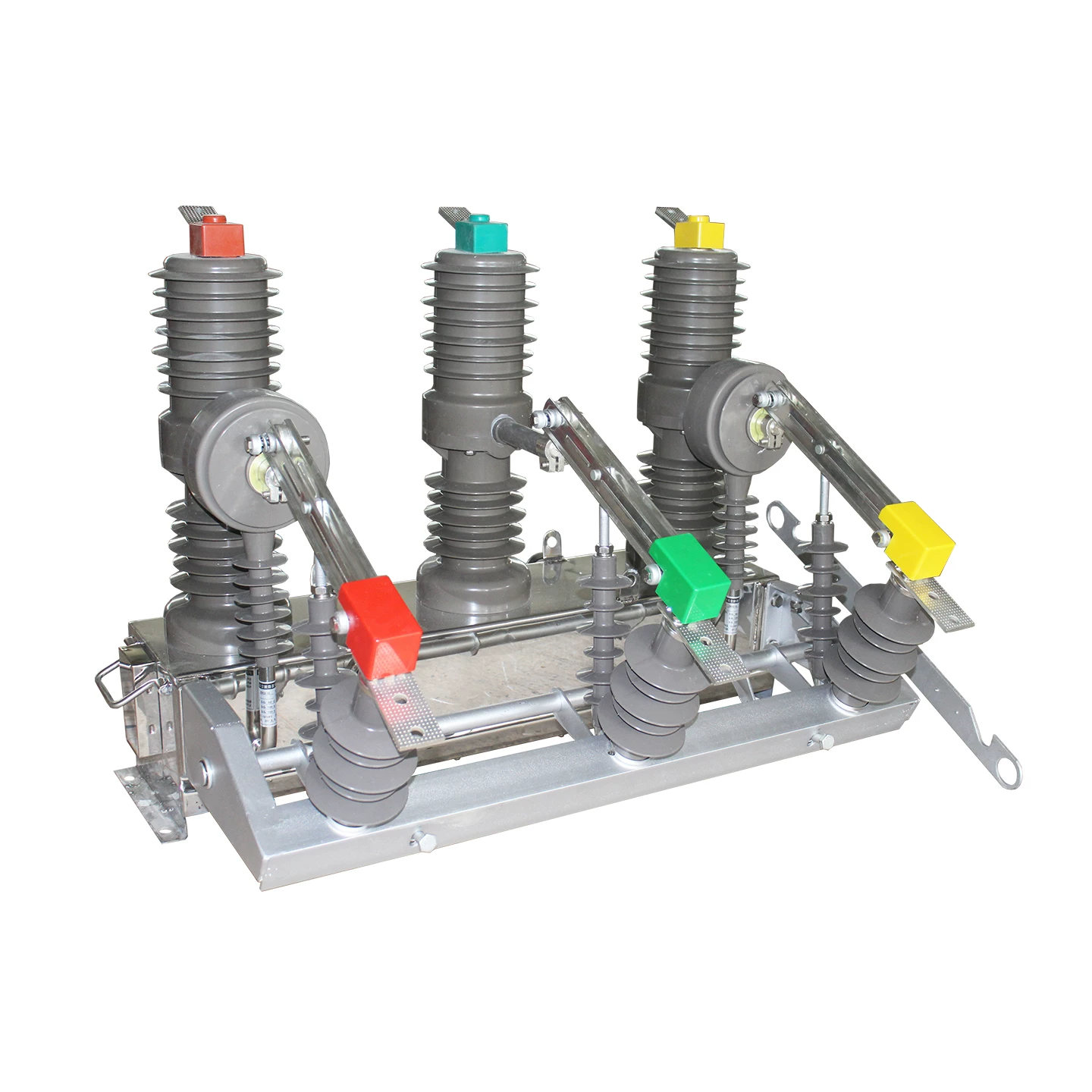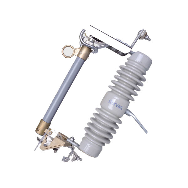
One small protective device can save an entire electrical system in a fraction of a second. A high rupturing capacity fuse is designed to interrupt massive fault currents before cables overheat, panels arc, or expensive machines suffer catastrophic damage.
In modern electrical protection, that speed matters. In many industrial and commercial installations, prospective short-circuit current can rise to tens of kiloamps, far beyond what ordinary low-capacity protection devices can safely clear.
Why One Small Fuse Can Prevent Catastrophic Electrical Failure

Electrical faults do not wait. A severe short circuit can release extreme thermal and mechanical energy almost instantly.
When the protection device cannot interrupt that energy safely, the result may include fire, arc flash, busbar damage, transformer stress, and complete equipment failure. This is why HRC protection is widely used where fault levels are high, and reliability is non-negotiable.
The Problem: Why Ordinary Protection Devices Fail During High Fault Currents
Standard fuses and lower-duty protective devices may work well for light overloads. However, under very high fault current, they may not interrupt the circuit quickly or safely enough.
If a device has insufficient breaking strength, it may rupture violently, sustain a dangerous arc, or allow fault energy to pass into downstream equipment. That risk is exactly what the high rupturing capacity fuse working principle is designed to address.
What Is a High Rupturing Capacity (HRC) Fuse?
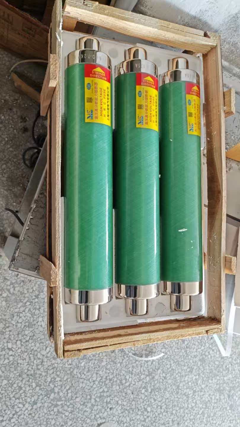
An HRC fuse is a sealed cartridge fuse built to withstand and interrupt very high short-circuit currents without exploding or causing uncontrolled arcing.
It usually consists of a strong ceramic body, metallic end caps, a carefully designed fuse element, and an arc-quenching filler such as silica sand. Its purpose is simple: clear dangerous faults safely, quickly, and predictably.
High Rupturing Capacity Fuse Working Principle
The high rupturing capacity fuse working principle is based on controlled melting and safe arc extinction. When current exceeds the fuse element's design limit, the element heats up and melts.
As the element separates, an arc forms. Inside an HRC fuse, the filler material absorbs heat, cools the arc, and helps extinguish it rapidly, allowing the circuit to be isolated before destructive fault energy spreads.
HRC Fuse Construction and Operation
The HRC fuse construction and operation are engineered for fault control, not just current interruption. Every internal part has a clear electrical and thermal role.
Ceramic body: provides mechanical strength and heat resistance.
Metallic end caps: ensure secure electrical connection.
Silver or silver-plated fuse element: offers stable and predictable melting characteristics.
Silica sand or similar filler: quenches the arc and absorbs fault energy.
Striker mechanism: available in some designs to trigger indication or linked disconnection.
This robust design is one reason HRC fuses remain highly trusted in industrial and distribution applications.
How an HRC Fuse Works Step by Step
Normal Operating Condition
Under normal load, the fuse carries its rated current without excessive heating. It remains stable and does not interrupt the circuit during acceptable operating conditions.
Overload and Short-Circuit Condition
When current rises above the permissible level, the fuse element heats rapidly. During severe faults, it melts almost instantly and initiates the interruption process.
Arc Quenching and Circuit Isolation
After the element melts, an arc forms between the separated ends. The filler material, commonly silica sand, cools and deionizes the arc path, stopping current flow and isolating the faulty section safely.
HRC Fuse Breaking Capacity and Ratings
HRC fuse breaking capacity and ratings determine whether a fuse is suitable for a given installation. Selection should never be based on current rating alone.
Current rating: the continuous current the fuse can carry under specified conditions.
Voltage rating: the maximum system voltage at which the fuse can interrupt safely.
Breaking capacity: the maximum fault current the fuse can safely interrupt without dangerous failure.
Fusing factor: ratio of minimum fusing current to rated current.
Time-current characteristic: shows how fast the fuse responds to different overcurrent levels.
In practical design, engineers compare available fault current with the fuse's certified interrupting capacity. The fuse must have a breaking capacity above the prospective fault level at its point of installation.
HRC Fuse Ratings Table
| Fuse Type / Class | Typical Current Rating | Typical Voltage Class | Typical Breaking Capacity | Common Use |
|---|---|---|---|---|
| LV HRC Fuse | 2 A to 125 A | 415 V AC | 50 kA to 80 kA | Motor feeders, panels, branch circuits |
| LV HRC Fuse | 160 A to 400 A | 500 V AC | 80 kA to 100 kA | Distribution boards, feeders, switchgear |
| Industrial Cartridge HRC | 16 A to 630 A | 690 V AC | 80 kA to 120 kA | Heavy industrial protection |
| Semiconductor Protection Fuse | 25 A to 800 A | 690 V AC | 100 kA to 200 kA | Drives, rectifiers, power electronics |
Actual ratings vary by manufacturer, fuse class, and standard. Always verify IEC, BS, or UL data before final selection.
HRC Fuse Construction Materials Table
| Part | Common Material | Function |
|---|---|---|
| Fuse Body | Ceramic / Porcelain | Provides insulation, heat resistance, and mechanical strength |
| End Caps | Copper, Brass, or Silver-Plated Metal | Connects the fuse securely into the circuit |
| Fuse Element | Silver or Silver Alloy | Melts under overcurrent to initiate protection |
| Filler | Silica Sand | Quenches arc, absorbs heat, and limits fault energy |
| Striker Pin | Metal Spring and Pin Assembly | Provides indication or triggers linked mechanisms in some designs |
HRC Fuse vs MCB: What Is the Difference?
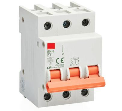
The difference between HRC fuse and MCB is important in real installations. Both provide overcurrent protection, but they are not interchangeable in every application.
An HRC fuse is usually faster under severe short-circuit conditions and often offers much higher fault interruption capability in compact form. An MCB, by contrast, can be reset after tripping and is highly convenient for routine building protection.
In simple terms, the difference between HRC fuse and MCB comes down to fault duty, reset convenience, selectivity, maintenance practice, and the required level of backup protection.
Difference Between HRC Fuse and MCB Table
| Feature | HRC Fuse | MCB |
|---|---|---|
| Operating Principle | Fuse element melts under overcurrent | Thermal-magnetic tripping mechanism |
| Reusability | Single use; must be replaced after operation | Resettable after trip |
| Short-Circuit Response | Very fast, especially at high fault levels | Fast, but depends on trip curve and interrupting rating |
| Breaking Capacity | Typically very high | Limited to device rating, often lower than industrial HRC fuses |
| Maintenance | Requires replacement stock and correct matching | Easy reset, simpler for frequent operation |
| Best Use Case | High fault level circuits, backup protection, motors, transformers | Final circuits, building distribution, user-friendly operation |
| Limitation | Not reusable | May not match HRC fuse performance in extreme fault duty |
HRC Fuse Applications in Electrical Systems
HRC fuse applications in electrical systems are broad because many installations require compact, reliable, and high-duty fault protection.
Motor circuits: protects feeders and starters against severe short circuits.
Transformer secondary protection: limits fault energy on low-voltage sides.
Industrial distribution panels: provides dependable backup protection.
Capacitor banks: protects against fault currents and internal failures.
Switchgear assemblies: supports coordination and high breaking requirements.
Cable feeders: reduces thermal and mechanical stress during faults.
These are among the most common HRC fuse applications in electrical systems where dependable interruption is critical.
Real-World Examples of HRC Fuse Use
Industrial motor protection: A manufacturing plant with multiple 75 kW motors may use HRC fuses upstream of contactors to provide high-speed short-circuit protection. This helps protect cables and motor starters from destructive fault energy.
Transformer secondary protection: In a commercial building with an 11 kV/415 V transformer, the low-voltage outgoing side may face high prospective fault current close to the transformer terminals. HRC fuses are often selected because ordinary low-duty devices may not have adequate breaking strength.
Backup protection in switchgear: In fused switch-disconnectors, HRC fuses are commonly used as reliable backup protection for downstream equipment. Their current-limiting action can significantly reduce let-through energy during major faults.
Real-World Data: Typical Fault Levels and Protection Needs
Fault level depends on transformer size, impedance, conductor length, and system configuration. Close to a large low-voltage transformer, fault current can be very high.
For example, a 1000 kVA, 415 V transformer with around 5% impedance can produce a theoretical full-load current of roughly 1390 A and a prospective secondary short-circuit current in the region of 27 kA to 29 kA at the terminals. Larger transformers or lower system impedance can push that number much higher.
In many industrial plants, available fault current at main low-voltage boards may exceed 35 kA, 50 kA, or even 65 kA. In such locations, the selected protective device must have sufficient high rupturing capacity to interrupt the fault safely.
This is why HRC fuse breaking capacity and ratings are central to protection studies. A fuse with inadequate breaking capacity is not merely undersized; it can be dangerous.
Sample Protection Data Table
| Example Electrical System | Estimated Fault Current | Selected HRC Fuse Rating | Protection Objective |
|---|---|---|---|
| 415 V motor control panel near 800 kVA transformer | 25 kA | 100 A, 415 V, 80 kA HRC fuse | Protect motor feeder and limit short-circuit damage |
| Main LV board near 1000 kVA transformer | 28 kA | 250 A, 500 V, 80 kA HRC fuse | Secure feeder protection and safe fault interruption |
| Industrial switchgear section | 50 kA | 400 A, 690 V, 100 kA HRC fuse | High-duty backup protection for downstream circuits |
| Capacitor bank feeder | 35 kA | 160 A, 500 V, 80 kA HRC fuse | Protect capacitor assembly from internal and external faults |
| Drive/semiconductor circuit | 65 kA | Special semiconductor fuse, 690 V, 150 kA | Ultra-fast protection of sensitive power electronics |
Key Benefits of High Rupturing Capacity Fuses
Fast fault clearing: minimizes thermal and mechanical stress.
High breaking capacity: suitable for circuits with large available fault current.
Reliable operation: simple protective principle with proven industrial use.
Compact design: high performance in limited panel space.
Strong backup protection: pairs well with contactors, isolators, and switchgear.
Current-limiting action: can reduce let-through energy during severe faults.
Limitations of HRC Fuses
No device is perfect. HRC fuses also have practical limitations.
One-time operation: once it blows, it must be replaced.
Replacement cost: spare inventory and downtime must be considered.
Rating sensitivity: wrong current, voltage, or breaking capacity can compromise protection.
No simple reset: less convenient than MCBs for non-critical nuisance trips.
How to Select the Right HRC Fuse
Selecting the right fuse requires more than reading the ampere value printed on the body. Proper specification should consider the full electrical context.
1. Match the current rating to the load and expected operating conditions.
2. Check the voltage rating so the fuse is suitable for the system voltage.
3. Confirm breaking capacity is greater than the prospective fault current at that location.
4. Consider load type such as motor, transformer, capacitor, cable, or semiconductor duty.
5. Review coordination with upstream and downstream protective devices.
6. Evaluate ambient conditions including enclosure temperature and installation method.
7. Use manufacturer curves for time-current performance and let-through energy.
In professional practice, fault studies and protection coordination reviews are strongly recommended before finalizing device selection.
Common Mistakes When Choosing an HRC Fuse
Undersized breaking capacity: selecting a fuse with an interrupting rating below the available fault current.
Wrong voltage class: using a fuse not intended for the system voltage.
Poor coordination: causing unnecessary upstream operation or loss of selectivity.
Ignoring load characteristics: especially in motors, capacitor banks, and semiconductor circuits.
Replacing with non-equivalent fuse types: same amp rating does not mean same protection performance.
Not checking standards compliance: IEC, BS, and UL classes are not always interchangeable.
FAQ
What is the main purpose of a high rupturing capacity fuse?
The main purpose of a high rupturing capacity fuse is to interrupt very high fault currents safely before they damage cables, switchgear, transformers, motors, or other electrical equipment. It is specifically designed for severe short-circuit conditions where ordinary protection may fail dangerously.
How does an HRC fuse differ from a normal fuse?
An HRC fuse differs from a normal fuse in its sealed construction, stronger body, arc-quenching filler, and much higher breaking capacity. It can interrupt heavy fault currents safely and predictably, while ordinary fuses may not withstand the same fault energy.
What is the difference between HRC fuse and MCB?
The difference between HRC fuse and MCB is that an HRC fuse is a sacrificial device with very strong short-circuit interruption performance, while an MCB is a resettable breaker designed for convenience and repeated operation. HRC fuses are often preferred where fault levels are high and current-limiting performance is important.
Where are HRC fuses used in electrical systems?
HRC fuses are used in motor feeders, transformer secondary circuits, industrial distribution panels, capacitor banks, fused switchgear, cable protection, and semiconductor circuits. They are especially common where high fault current and dependable isolation are critical.
What does breaking capacity mean in an HRC fuse?
Breaking capacity means the maximum fault current the HRC fuse can safely interrupt without bursting, sustaining a dangerous arc, or failing in an unsafe manner. It must always be higher than the prospective short-circuit current at the installation point.
Can an HRC fuse be reused after it blows?
No. An HRC fuse is a one-time protective device. After it operates, it must be replaced with the correct equivalent fuse of the same specification and approved type.
How do I choose the correct HRC fuse rating?
Choose the correct HRC fuse by checking current rating, voltage rating, available fault current, load type, coordination requirements, and environmental conditions. For critical systems, use fault calculations and manufacturer time-current data, and confirm the selection with a qualified electrical engineer.
Conclusion: Why HRC Fuses Matter in Modern Electrical Protection
HRC fuses remain one of the most dependable solutions for high-fault-current protection. Their controlled melting action, arc-quenching construction, and strong interrupting performance make them essential in many industrial and commercial systems.
When fault energy is high, device quality and rating accuracy are not optional. A properly selected high rupturing capacity fuse can be the difference between a safely isolated fault and costly electrical destruction.
Choose the Right Circuit Protection for Safer Systems
Do not guess when fault levels are high. Review your system fault current, compare HRC fuse breaking capacity and ratings, and verify coordination before installing or replacing protective devices.
Take action now: assess your protection scheme, compare the difference between HRC fuse and MCB for your application, and consult a qualified electrical engineer to choose the right HRC fuse for safer, more reliable electrical systems.