An SF₆ three-position load break switch is a medium-voltage gas-insulated switch that combines three functions in one sealed device: load switching, isolation, and grounding. If you work with ring main units, compact substations, or gas-insulated medium voltage switchgear, this is one of the most important devices to understand. Read this article, and you will quickly get familiar with its working logic, where it is used, why engineers choose it, what field teams really worry about, and how to judge whether it is the right fit for your project.
What Is an SF₆ Three-Position Load Break Switch?

An SF₆ three-position load-break switch is a medium-voltage switch installed inside a sealed gas tank, usually filled with sulfur hexafluoride gas, that combines closed, open, and earthed positions in a single integrated mechanism.
In practical terms, it lets operators energize a feeder, isolate it, and then ground it safely before maintenance. This is why it is common in ring main unit SF6 switch applications and compact GIS panels.
Why This Switch Matters in Medium-Voltage Power Systems
This switch matters because medium-voltage distribution is not just about turning power on and off. It is about doing it in a way that is safe, compact, repeatable, and easy to interlock.
By the end of this article, you will understand its role, operating logic, safety value, and common use cases. More importantly, you will understand what buyers and operators often miss before a project goes live.
The Core Problem It Solves in Real Projects
In real projects, utilities and industrial sites need a switch that fits in small spaces and still provides reliable switching, visible status indicators, and safe grounding. That need becomes acute in urban RMUs, prefabricated substations, mining skids, and offshore or infrastructure installations where room is tight.
I have seen this problem most clearly in compact secondary substations: teams wanted a smaller footprint, but they also wanted fewer operator steps and fewer chances for dangerous sequence errors. That is exactly where the disconnect grounding load break switch concept becomes valuable.
How an SF₆ Three-Position Load Break Switch Works
The three-position switch disconnector operation is simple in theory but critical in practice. One mechanism moves the internal contacts between service, isolation, and grounding positions under interlocked control.
Closed Position
In the closed position, the main contacts are engaged and current flows normally through the feeder or transformer circuit. The switch carries rated load current during normal service.
This is the operating state for standard network operation. In RMUs, this is the position used while the ring or outgoing feeder is energized.
Open/Isolated Position
In the open or isolated position, the current path is disconnected. The circuit is separated for sectionalizing, maintenance preparation, or operational switching.
This position does not yet mean the cable is safe to touch. It only means the electrical path has been opened according to the switch design.
Grounded/Earthed Position
In the earthed position, the downstream cable or feeder is connected to ground. This removes dangerous residual or induced voltage risk before work begins.
On-site, this is the position that crews care about most. Many incidents are not caused by switching itself, but by assuming a circuit is safe before correct grounding is confirmed.
SF₆ Three-Position Load Break Switch Function at a Glance
The SF6 three-position load break switch function can be summarized in three points:
Switch load current during normal operation
Provide disconnection for isolation and sectionalizing
Enable grounding in one integrated, interlocked structure
This integrated design reduces panel complexity. It also reduces the number of separate devices the operator must interpret under pressure.
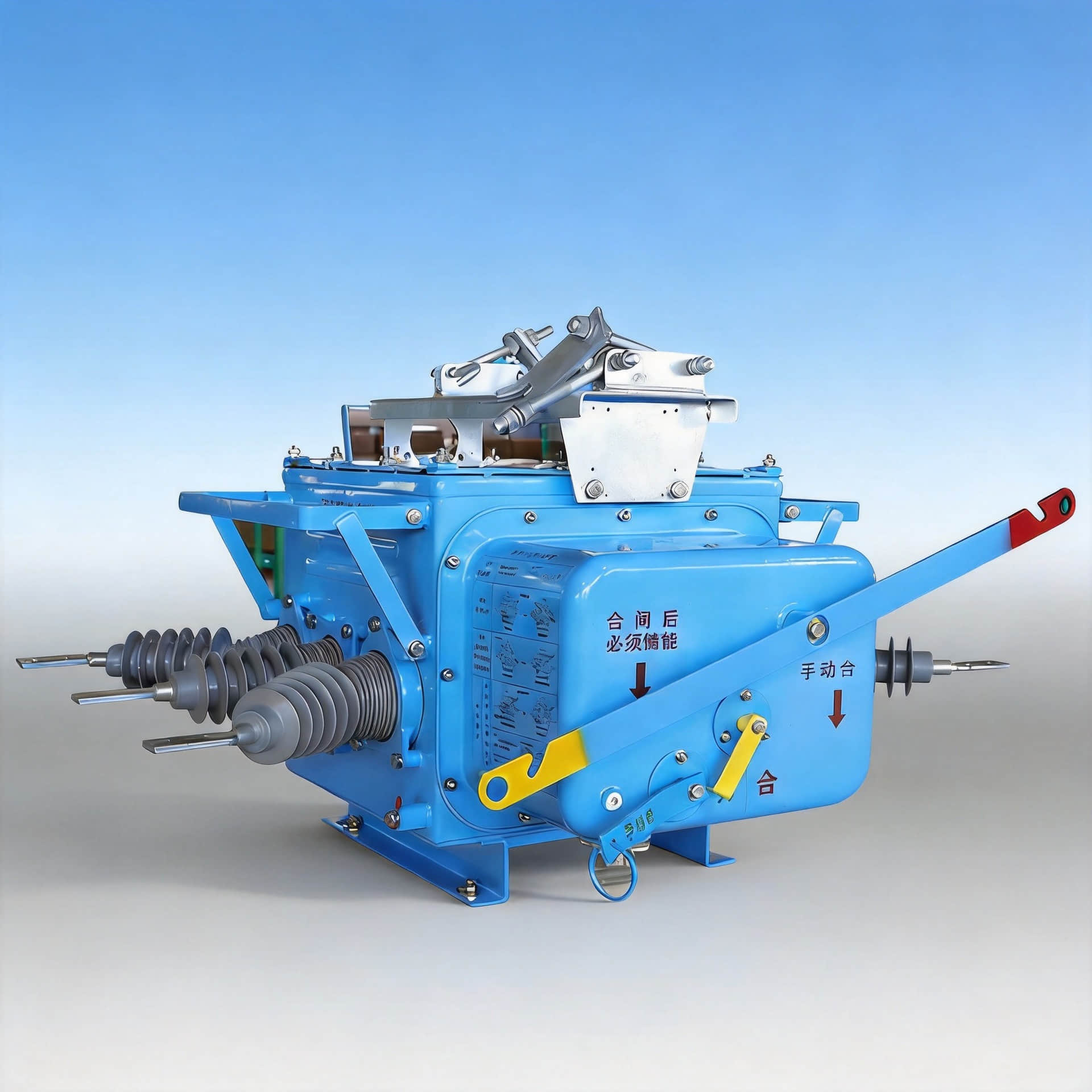
Key Components Inside the Switch
Typical internal parts include:
Main and earthing contacts
Stored-energy or manual operating mechanism
Arc-quenching chamber
Sealed gas tank
Mechanical and electrical interlocks
Position indicators
Drive shafts and linkage parts
In better designs, the position indication is directly linked to the internal shaft, not just the handle. That detail matters more in the field than many brochures admit.

Why SF₆ Gas Is Used in Gas-Insulated Medium-Voltage Switchgear
SF₆ is used because it offers excellent dielectric strength and strong arc-extinguishing performance. That allows compact dimensions and reliable insulation inside gas-insulated medium voltage switchgear.
This is one reason utilities adopted it widely in RMUs and GIS. It performs well in harsh environments, especially where dust, humidity, salinity, or constrained installation space make air-insulated solutions less practical.
At the same time, environmental pressure is real. SF₆ has a very high global warming potential, so many markets now demand tighter leak control, reporting discipline, gas recovery, and transition planning toward low-GWP or vacuum-based alternatives.
Relevant design and testing frameworks often reference IEC 62271 series requirements for high-voltage and medium-voltage switchgear, and utility buyers may also benchmark designs and test methods against IEEE practices depending on region and project specification.
SF₆ vs Vacuum vs Air-Insulated Alternatives
SF₆ designs are usually chosen for compactness and strong insulation in sealed enclosures. Vacuum solutions are increasingly preferred for environmental reasons, especially in newer sustainability-led procurement models.
Air-insulated equipment remains useful where space is less constrained and visual inspection is a priority. But it typically needs a larger footprint and more environmental protection.
| Technology | Main Strength | Main Limitation | Typical Fit |
|---|---|---|---|
| SF₆ insulated | Compact, mature, strong insulation | Gas compliance and leak management | RMU, GIS, compact substations |
| Vacuum | Low environmental burden, strong interruption performance | Some designs still larger or newer in certain layouts | Modern MV switchgear, eco-focused projects |
| Air insulated | Simpler gas-free design, easier visual access | Larger size, more environmental sensitivity | Spacious substations, indoor electrical rooms |
Typical Ratings and Technical Parameters
Before selection, engineers compare voltage class, current rating, short-circuit withstand, insulation level, operating frequency, gas pressure, and mechanical endurance. Buyers should also ask whether the switch is intended for feeder duty, transformer protection schemes, or sectionalizing only.
Table: Common Medium-Voltage Ratings for SF₆ Three-Position Load Break Switches
| Parameter | Typical Range | What It Means in Practice |
|---|---|---|
| Rated voltage | 12 kV / 24 kV / 36 kV | Matches system insulation and network class |
| Rated current | 630 A / 1250 A | Normal continuous load-carrying capability |
| Short-time withstand current | 16 kA / 20 kA / 25 kA for 1 s to 3 s | Ability to withstand fault stress for a defined time |
| Power frequency | 50 Hz / 60 Hz | Network compatibility |
| Gas pressure | Varies by design, often sealed-for-life class | Affects insulation performance and monitoring strategy |
| Mechanical endurance | 1,000 to 10,000+ operations | Expected operating life of the mechanism |
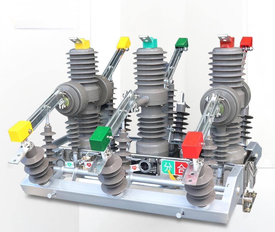
Where It Is Used: Ring Main Unit SF₆ Switch Applications
Ring main unit SF6 switch applications are common wherever compact medium-voltage distribution is required. The typical pattern is simple: limited space, high reliability requirement, and a need for safe sectionalizing.
Utility Ring Main Units
Utilities use these switches in urban cable loops, roadside kiosks, and compact secondary substations. In dense city networks, every square meter matters.
A practical example is downtown distribution, where a three-way or four-way RMU must fit into a small concrete enclosure. The integrated three-position design reduces equipment count and simplifies operator training.
Industrial Power Distribution
Factories, mines, petrochemical sites, and data centers use them for feeder switching and transformer isolation. Industrial users value them because the switch can isolate and ground the feeder within one controlled sequence.
In heavy industry, the concern is often not theory but downtime. If one feeder needs work, teams want fast sectionalizing without confusing manual steps.
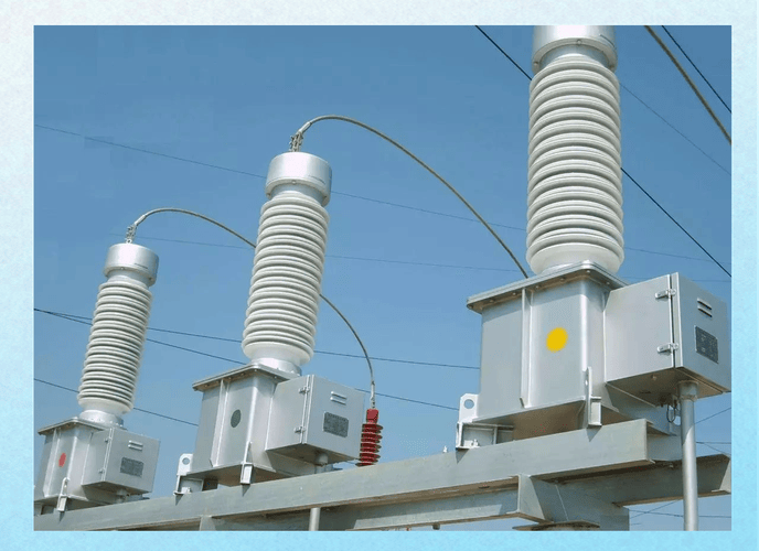
Renewable and Infrastructure Projects
Wind farms, solar collection systems, airports, rail networks, tunnels, and commercial campuses also use them. These projects often combine weather exposure, cable-heavy layouts, and tight prefab substation designs.
I have seen project teams choose SF₆ designs in transport and energy sites mainly because panel width and cable chamber arrangement were the real decision drivers, not just the switch nameplate.
Disconnect Grounding Load Break Switch: Why the Three Functions Are Combined
The logic is straightforward. If switching, disconnection, and grounding are handled by separate devices, the operator has more steps, more ambiguity, and more opportunity to make a sequence mistake.
When these three functions are combined into one interlocked device, safety improves and panel design becomes cleaner. This is why the disconnect grounding load break switch approach remains popular in medium-voltage GIS and RMU systems.
Operating Sequence and Safety Interlocks
The correct operating sequence is essential. A well-designed switch uses mechanical and sometimes electrical interlocks so the operator cannot move directly from closed to earthed under unsafe conditions.
Most standard logic is: closed → open → earthed, and the reverse when returning to service. Interlocks are there to block dangerous shortcuts.
Table: Normal Operating Sequence for Closed, Open, and Earthed Positions
| Current Position | Allowed Action | Blocked Action | Safety Purpose |
|---|---|---|---|
| Closed | Move to open | Direct move to earthed | Prevents grounding an energized circuit |
| Open | Move to closed or earthed | Unsafe forced transition bypassing mechanism | Ensures controlled isolation before grounding |
| Earthed | Move back to open | Direct return to closed in some designs without a release sequence | Prevents accidental energization of grounded cable |

Real-World Field Issues Users Discuss Online
Across practitioner communities and user discussions, the same concerns keep coming up. Not abstract theory. Real operating confidence, leak behavior, maintenance logistics, and whether the panel tells the truth about its internal state.
Operators Worry About Position Certainty More Than Theory
The biggest operator concern is often simple: Does the position indicator truly reflect the internal contact position? In field discussions, crews repeatedly say they trust direct mechanical indication more than decorative front-panel labels.
One recurring insight from service technicians is that after years of operation, linkage wear, handle feel, and indicator alignment matter more than catalog language. The best buyers ask how the position indication is mechanically verified.
Maintenance Teams Focus on Gas Leaks, Seals, and Lifecycle Cost
Maintenance teams talk a lot about slow gas leakage, seal aging, refill logistics, and shutdown planning. Not because leaks are constant, but because when they happen, the disruption is expensive and procedural.
A non-obvious field detail is that some sites struggle less with the switch itself than with gas service readiness: trained personnel, cylinder handling, recovery tools, and paperwork. That lifecycle burden is rarely visible in early procurement meetings.
Non-Experts Often Miss the Earthing Step Risk
Many non-specialists assume that open means safe. Experienced operators know that is a dangerous assumption.
In real field anecdotes, the risk often comes from induced voltage, backfeed, or unverified cable condition. The earthing step is not a formality. It is the point where maintenance safety becomes real.
Compact Design Helps in Tight Rooms but Complicates Inspection
A compact GIS layout is a major advantage in cramped electrical rooms. But it also means internal parts are less visible than in open-air-insulated gear.
That tradeoff appears often in user feedback: less space, better protection, harder direct inspection. This is why buyers should pay close attention to diagnostics, gas monitoring, and mechanism access.
Real-World Data and Practical Examples
Actual selection decisions usually come down to a few site realities: fault level, room size, maintenance model, and operator skill. Below is a practical summary based on common project patterns seen across utility and industrial tenders.
Table: Example Use Cases, Site Conditions, and Switch Selection Logic
| Sector | Voltage Level | Site Constraint | Why the SF₆ Three-Position Design Was Chosen | Key Takeaway |
|---|---|---|---|---|
| Urban utility RMU | 12 kV | Very limited kiosk space | Compact GIS layout with integrated isolation and earthing | Best fit when footprint is the top priority |
| Factory distribution | 24 kV | Need a fast feeder sectionalizing | Simple interlocked operation for maintenance isolation | Reduces operator error during downtime events |
| Wind farm collection | 36 kV | Prefabricated substation size limits | Sealed insulation performs well in remote environments | Useful where access is difficult and reliability matters |
| Airport or rail project | 24 kV | High service continuity requirement | RMU architecture supports network flexibility | Switching logic matters as much as rating |
Advantages of an SF₆ Three-Position Load Break Switch
Compact size for RMU and GIS applications
Integrated safety through switching, isolation, and grounding
Strong insulation performance in sealed enclosures
Low routine maintenance in many sealed-for-life designs
High suitability for gas-insulated medium voltage switchgear
Reduced wiring and device count compared with multi-device arrangements
Limitations and Selection Risks
The main limitation is environmental. SF₆ requires serious compliance discipline because of its high greenhouse impact.
Other risks include gas handling requirements, technician training, leak management, and long-term replacement planning. Buyers should also consider future regulations, spare parts support, and whether their own organization is prepared for SF₆ lifecycle management.
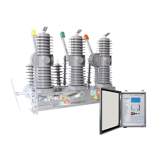
How to Choose the Right SF₆ Three-Position Load Break Switch
Choose based on the real duty, not just the headline rating. Start with system voltage, continuous current, fault withstand requirement, panel arrangement, and whether you need motorized operation, remote indication, or integrated protection coordination.
Then verify standards compliance, interlock logic, gas sealing approach, and after-sales service capability. For utility and industrial projects, ask for type test evidence aligned with relevant IEC 62271 requirements and any project-specific IEEE references.
Table: Buyer Checklist for Evaluating SF₆ Three-Position Switches
| Selection Criteria | Why It Matters | Questions to Ask Suppliers | Red Flags |
|---|---|---|---|
| Rated voltage and current | Must match system duty | What are the continuous and short-term ratings? | Only generic catalog values, no project confirmation |
| Short-circuit withstand | Critical for network safety | What is the tested withstand current and duration? | Unclear test basis |
| Interlock design | Prevents operator mistakes | Can closed, open, and earthed positions be mechanically verified? | Weak explanation of blocking logic |
| Gas sealing method | Affects lifecycle reliability | What is the leakage rate and service expectation? | No clear gas lifecycle statement |
| Standards compliance | Supports acceptance and trust | Which IEC or IEEE-related tests were completed? | Compliance claims without reports |
| Service support | Important for long-term operation | Who handles spare parts, gas service, and training? | No local or regional support plan |
Installation, Inspection, and Maintenance Basics
Installation starts with correct mounting, cable termination quality, torque control, and verification of the operating sequence. Commissioning should include functional checks of position indication, interlocks, and grounding operation.
For maintenance, teams usually focus on gas condition or gas density indication where applicable, mechanism movement, auxiliary contact verification, and visual condition of accessible parts. Inspection intervals depend on design, duty cycle, and manufacturer guidance.
In my experience, the most effective maintenance teams do one thing consistently: they record, handle, feel, timing, and indicator behavior over time. Those small changes often reveal trouble before alarms do.
Common Mistakes to Avoid
Assuming open means safe to work without grounding
Ignoring gas alarms or density warnings
Using a switch on a feeder with a duty beyond its rating
Skipping interlock function checks during commissioning
Buying only on price without checking service capability
Failing to train operators on the exact switching sequence
Overlooking future environmental compliance requirements

FAQ
What is the difference between an SF₆ load break switch and a circuit breaker?
An SF₆ load break switch is mainly designed for normal load switching, isolation, and often grounding, depending on the design. A circuit breaker is designed to interrupt fault current repeatedly under specified protection conditions, which is a different duty level.
What are the three positions of a three-position load break switch?
The three positions are closed, open, and earthed. Closed means the feeder is in service, open means it is disconnected, and earthed means the isolated circuit is connected to ground for safety.
Is an SF₆ three-position load break switch the same as a switch disconnector?
The terms overlap in many projects. In practice, a three-position switch disconnector usually refers to a design that combines switching and isolating functions, and in many GIS or RMU applications, it also includes an earthing position within the same integrated mechanism.
Why is grounding built into the switch?
Grounding is built into improve maintenance safety and reduce operator error. With interlocked grounding in the same device, the correct sequence is easier to enforce, and the risk of unsafe assumptions is lower.
Where are SF₆ three-position load break switches commonly used?
They are commonly used in RMUs, compact substations, industrial distribution systems, utility cable networks, renewable energy collection systems, and infrastructure projects such as airports and rail facilities.
What are the main disadvantages of SF₆ switchgear?
The main disadvantages are environmental impact, leak management requirements, regulatory pressure, and the need for proper end-of-life gas recovery and handling. These factors can increase long-term compliance costs.
How do you maintain an SF₆ three-position load break switch?
Maintenance typically includes periodic inspection, gas monitoring where applicable, interlock checks, mechanism testing, auxiliary contact verification, and following the manufacturer’s service instructions. Good maintenance also tracks operating feel and status indication consistency.
Is SF₆ technology still used, or is it being replaced?
It is still widely used and remains common in installed medium-voltage networks. However, it is increasingly challenged by vacuum and low-GWP alternatives as environmental regulations and customer procurement policies evolve.
Conclusion: When an SF₆ Three-Position Load Break Switch Is the Right Choice
An SF₆ three-position load break switch is the right choice when you need compact size, dependable insulation, interlocked safety, and efficient medium-voltage feeder operation in a confined enclosure. It fits especially well in RMUs, GIS panels, urban substations, and industrial systems where switching, isolation, and grounding must be combined cleanly.
Its value is strongest where space is expensive and operator sequence control matters. Its risks are manageable, but only if the buyer takes gas compliance, service support, and long-term environmental planning seriously.
CTA
If you are comparing specifications, planning a new RMU or GIS project, or replacing an existing medium-voltage switch, we can help you evaluate the right SF₆ three-position load break switch for your duty and budget.
Send us an inquiry today for datasheets, technical consultation, and model selection support. If you want a faster discussion, contact us on WhatsApp, and our team will help you match the right switch to your project requirements.