What is an Earthing Switch?
An Earthing Switch, often referred to as a grounding switch, is a critical mechanical switching device used in high-voltage (HV) transmission and distribution systems. At Weisho Electric, we engineer these components to serve as a definitive safety barrier, connecting de-energized parts of a circuit directly to the ground. Whether integrated into indoor switchgear or installed in outdoor substations, the primary goal is to ensure that electrical equipment is safe for maintenance by eliminating the risk of accidental energization.
Definition and Electrical Symbol
Technically, an earthing switch is defined as a device capable of grounding a circuit for a specified duration, even under abnormal conditions like a short circuit. In electrical schematics, it is universally represented by a switch symbol connecting to the standard earth ground icon—three horizontal lines of diminishing width.
Our product portfolio, including the widely used JN15 and JN17 series, is designed to meet international standards for voltage ratings ranging from 12kV to 126kV. These devices are integral to power systems, providing the physical assurance that a line is grounded and safe for human intervention.
Basic Working Principle and Mechanism
The operation of an earthing switch relies on a robust mechanical linkage that drives moving contacts into engagement with fixed grounded contacts. When the switch closes, it creates a low-impedance path that instantly discharges any residual static electricity or induced voltage to the earth.
Contact Materials: We utilize high-conductivity copper contacts, often silver-plated, to minimize contact resistance and prevent oxidation.
Actuation: Our designs feature reliable spring-actuated mechanisms, available in both manual and motor-driven options, ensuring rapid and decisive closing capabilities.
Structural Integrity: Supported by high-strength epoxy resin or porcelain insulators, our switches maintain mechanical rigidity and electrical isolation during operation.
Fault Handling: Crucially, Weisho earthing switches are rated to withstand short-circuit making currents, maintaining thermal stability without sustaining damage during fault conditions.
The Importance of Earthing in Electrical Safety
Safety is the non-negotiable priority in high-voltage engineering. The earthing switch functions as the final line of defense for maintenance personnel working on substations, industrial power networks, and transmission lines.
Residual Discharge: It safely drains capacitive charges that remain on lines after isolation.
Accidental Energization Protection: If a circuit is inadvertently powered while the earthing switch is closed, the device directs the current to the ground, triggering upstream protection relays to trip and protecting workers.
Quality Assurance: Adhering to ISO9001 quality management systems, Weisho Electric ensures that every unit delivers the mechanical endurance and insulation reliability required for these life-critical safety functions.
Primary Functions and Purpose

At Weisho Electric, we engineer our earthing switches to serve as the ultimate safety barrier in high-voltage systems. While a disconnector creates an open point, the earthing switch actively manages the electrical state of that isolated section. We design these components to ensure that “off” truly means safe, protecting both the infrastructure and the personnel working on it.
Safe Discharge of Residual Energy
The immediate function of an earthing switch is to drain residual static charge and induced voltage from a de-energized circuit. High-voltage cables and capacitor banks act like massive batteries, storing dangerous levels of energy even after the main power is cut.
When we close the earthing switch, it provides a low-impedance path to the ground, instantly dissipating this stored energy. This is a critical step before any personnel can approach the equipment. In many modern substations, our grounding switches are integrated with SF6 load break switches to streamline this isolation and grounding process, ensuring a verified zero-energy state.
Grounding Circuits for Maintenance Work
Once the residual energy is gone, the earthing switch remains closed to maintain a continuous connection to the earth during maintenance. This is the physical guarantee of safety for technicians.
Visual Confirmation: The mechanical position of the switch provides a clear visual indication that the line is grounded.
Accidental Re-energization Protection: If a circuit breaker is accidentally closed while a crew is working, the earthing switch directs that current straight to the ground rather than through the workers.
Induced Voltage Management: It continuously drains any voltage induced by adjacent live lines, which is common in crowded transmission corridors.
Short-Circuit Protection and Current Handling
A robust earthing switch must do more than just ground a dead line; it must survive a fault. This is defined as the short-circuit making capacity. If an earthing switch is inadvertently closed onto a live line, a massive fault current will flow.
We manufacture our switches, such as the JN15 series, using high-conductivity silver-plated copper contacts and heavy-duty springs. This construction allows the device to withstand the electromagnetic forces and thermal stress of a short-circuit current for a specified duration without welding shut or exploding. This capability triggers the upstream protection relays to trip the main breaker, minimizing damage to the substation.
Key Types of Earthing Switches

When we select equipment for a substation or distribution network, we don’t just grab a generic switch off the shelf. The specific application dictates the type of Earthing Switch (or Grounding Switch) required. We categorize these devices based on how they operate, how fast they react, and where they are installed.
Manual vs. Motor-Operated Switches
The primary distinction lies in the actuation method.
Manual Earthing Switches: These rely on a mechanical linkage system. An operator physically uses a handle or crank to close the switch. We typically use these in smaller setups or for maintenance-only switches where speed isn’t critical and automation isn’t available.
Motor-Operated Switches: In modern smart grids and high-voltage substations, we prefer motor-operated versions. These use an electric motor to drive the contacts. The biggest advantage here is safety and integration; operators can trigger the grounding process remotely via SCADA systems, keeping them far away from potential arc flashes.
High-Speed Earthing Switches (HSGS/FES)
Standard grounding switches are built to discharge residual static charge—they aren’t meant to close onto a live fault. That is where the High-Speed Earthing Switch (HSGS), often called a Fast Earthing Switch (FES), comes in.
These devices possess “short-circuit making capacity.” This means they use a spring-loaded mechanism to snap shut incredibly fast. If a line is accidentally energized or if there is a back-feed, the HSGS can safely close against that fault current to protect the equipment and extinguish secondary arcs. We usually install these at the line entrance of a substation.
Indoor and Outdoor High-Voltage Designs
The physical design changes drastically depending on the installation environment.
Indoor Designs: These are compact and often enclosed. You will find them integrated directly into metal-clad switchgear or Gas Insulated Switchgear (GIS). Space is at a premium here, so the switch is often part of a combined disconnector unit.
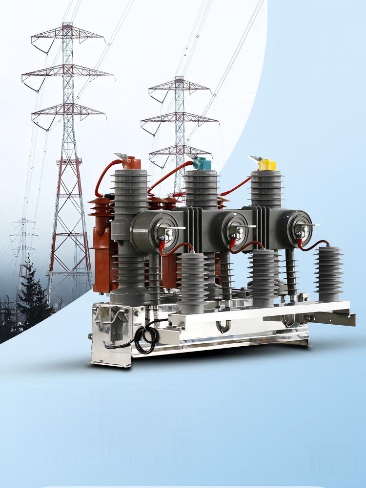
Outdoor Designs: These must be rugged enough to handle wind, ice, and pollution. They are typically air-insulated and mounted on large steel structures. In these open-air setups, the earthing switch often works in conjunction with primary isolation devices, such as the FZW28-12F outdoor boundary vacuum circuit breaker, to ensure that the section isolated by the breaker is firmly grounded before any crew touches it.
Critical Safety Interlocks and Operations
Safety in high-voltage environments isn’t about luck; it’s about engineered controls. We rely on robust interlock systems to prevent human error, ensuring that an Earthing Switch is never operated at the wrong time. These mechanical and electrical safeguards are the primary defense against catastrophic short circuits and arc flashes during maintenance.
Interlock Between Disconnector and Earthing Switch
The relationship between the disconnector (isolator) and the Grounding Switch is mutually exclusive. We design these systems so that it is physically impossible to close the earthing switch while the disconnector is in the closed (live) position.
Conversely, if the earthing switch is closed—meaning the system is grounded—the interlock prevents the disconnector from closing. This “either-or” mechanism ensures that a live line is never grounded and a grounded line is never energized.
Interlock with Circuit Breaker Systems
The protection scheme extends to the main breaking device. Before any grounding operation can occur, the load current must be completely interrupted. This is where the indoor vacuum circuit breaker plays a vital role in the safety chain.
The interlock logic dictates that the circuit breaker must be in the “Open” position before the Earthing Switch can be engaged. If the breaker is closed, the grounding mechanism remains locked out. This prevents the switch from closing onto a fault or a loaded circuit, which would exceed its making capacity and endanger personnel.
Standard Sequential Operating Procedures
To maintain safety and system integrity, we adhere to a strict order of operations. Deviating from this sequence will typically trigger the interlocks to block the action.
The standard sequence for grounding is:
1. Open the Circuit Breaker: Interrupt the current flow.
2. Open the Disconnector: Create a visible isolation gap from the power source.
3. Verify Voltage: Confirm the line is dead using a voltage detector.
4. Close the Earthing Switch: Safely discharge residual energy to the ground.
To restore power, we simply reverse this procedure: open the earthing switch first, close the disconnector, and finally close the circuit breaker.
Applications in Power Distribution Systems

Integration in High-Voltage Substations
In high-voltage substations, the earthing switch is a non-negotiable component for operational safety. We integrate these switches directly into the switchyard layout to isolate specific sections of the grid during maintenance. You will typically find them mounted on the base of disconnectors or built into Gas-Insulated Switchgear (GIS). Their primary job here is to ground the conductive parts to the substation’s earth mesh effectively.
For anyone trying to understand power grids and their safety protocols, recognizing the placement of these switches is key. They serve as the definitive visual confirmation that a section of the substation is de-energized and safe to touch.
Feeder, Transformer, and Bus-Coupler Bays
The specific application of a grounding switch depends heavily on which “bay” or section of the switchgear it protects. We configure them differently based on the equipment involved:
Feeder Bays: The switch is located at the cable termination point. Its main role is to discharge the capacitive charge remaining in long underground cables or overhead lines after the circuit breaker has tripped.
Transformer Bays: Here, the switch grounds the connections leading to the power transformer. This is critical for technicians performing oil sampling or bushing maintenance.
Bus-Coupler Bays: These switches are used to ground the main busbars. This allows us to safely work on the busbar system itself or extend the switchboard.
In many compact medium-voltage setups, manufacturers often combine these functions with an indoor load break switch, creating an all-in-one unit that handles both load switching and safety grounding.
Earthing Switches in Low-Voltage Switchgear
While high-voltage systems get the most attention, earthing switches are also utilized in robust low-voltage (LV) distribution systems (typically 480V or 600V in the US). In LV switchgear, we don’t always use standalone high-speed switches. Instead, the grounding function is often integrated into the draw-out mechanism of Air Circuit Breakers (ACBs) or achieved through portable grounding carriages.
However, for high-current Main Distribution Boards (MDBs), we install permanent grounding links or switches on the main busbars. This ensures that during major facility shutdowns or overhauls, the low-voltage busbars remain short-circuited to ground, preventing any risk of back-feed from backup generators or accidental re-energization.
Comparing Earthing Switches with Other Devices
In the high-voltage world, we use several devices that look similar but perform distinctly different roles. Understanding the specific function of an Earthing Switch compared to breakers and disconnectors is vital for designing safe substations and avoiding catastrophic operator errors.
Earthing Switch vs. Circuit Breaker
It is crucial not to confuse a grounding device with a breaking device. A circuit breaker is the “muscle” of the system—it is designed to interrupt current flow, specifically breaking the electrical arc under load or fault conditions. An Earthing Switch is not designed to break a live load.
The workflow is strictly sequential:
1. The Circuit Breaker opens to cut the power.
2. The Earthing Switch closes to ground the residual charge.
If you try to use a standard grounding switch to interrupt current, it will likely fail and cause an arc flash. While an SF6 circuit breaker handles the dynamic stress of cutting power, the earthing switch handles the static safety of the de-energized line.
Differences Between Disconnectors and Grounding Switches
Disconnectors (often called isolators) and grounding switches are often physically integrated, but they do opposite things. A disconnector creates a visible physical gap in the line to isolate the equipment from the power source. However, an open disconnector does not drain the energy; the line can still hold a lethal static charge.
That is where the grounding switch comes in. Once the outdoor disconnect switch has isolated the circuit, the grounding switch connects the conductor to the earth.
Quick Comparison:
| Feature | Disconnector (Isolator) | Earthing (Grounding) Switch |
|---|---|---|
| Primary Function | Isolates circuit (creates a gap) | Discharges residual energy to ground |
| Operation State | Operates off-load (usually) | Operates on de-energized circuits |
| Safety Role | Prevents current from reaching equipment | Prevents shock from stored energy |
| Symbol | Horizontal break | Vertical line to ground |
Relationship with High-Speed Grounding Switches
Standard maintenance earthing switches are relatively slow and are not built to close onto a live short circuit. However, a High-Speed Grounding Switch (HSGS) is different. We use these primarily for protection schemes in transmission lines.
Standard Earthing Switch: Used for maintenance safety. It has no “making capacity” (cannot safely close on a live fault).
High-Speed Grounding Switch: Equipped with a spring-loaded mechanism to snap shut instantly. It has a rated short-circuit making capacity.
If an operator accidentally closes an HSGS onto a live line, the switch is robust enough to contain the fault current until the main protection relays trip the circuit breaker, preventing an explosion. Standard switches would simply melt or explode under that stress.

Selection, Maintenance, and Safety Guidelines
Selecting the right equipment and maintaining it properly ensures your power system remains reliable and your personnel stay safe. We focus on durability and precision engineering, but understanding the technical requirements is the first step to a successful installation.
Key Technical Specifications and Selection Tips
When choosing an Earthing Switch, you must match the device specifications strictly to your system’s operational parameters. The primary factor is the rated voltage, which typically ranges from 12kV up to 126kV for our high-voltage solutions. You also need to verify the short-time withstand current (thermal stability) to ensure the switch can handle fault currents without sustaining damage.
For indoor applications, compatibility with existing switchgear is vital. For instance, if you are integrating components into a cabinet, you must ensure the earthing switch mechanically fits and electrically coordinates with the FZN21-12D indoor load break switch or similar isolation devices.
Selection Checklist:
Rated Voltage: Must match or exceed system voltage (e.g., 12kV, 24kV, 40.5kV).
Rated Short-time Withstand Current: Usually measured in kA (e.g., 20kA/4s).
Peak Withstand Current: The maximum dynamic current the switch can survive.
Environmental Conditions: Choose Indoor (JN15/JN17 series) or Outdoor models based on exposure.
Mechanism Type: Decide between manual operation or motorized control for remote switching.
Routine Maintenance and Inspection Intervals
High-voltage equipment requires regular inspection to prevent mechanical failure or insulation breakdown. While our grounding switches are designed for long service life with minimal maintenance, a standard check-up schedule is recommended to ensure the spring mechanisms and contacts remain in peak condition.
Recommended Maintenance Schedule:
| Inspection Component | Frequency | Action Required |
|---|---|---|
| Visual Inspection | Every 6 Months | Check for dust accumulation on insulators and signs of corrosion on the frame. |
| Contact Check | Annually | Inspect main contacts for burns or oxidation; clean silver-plated surfaces if necessary. |
| Mechanical Test | Annually | Operate the switch manually to ensure smooth opening/closing without jamming. |
| Lubrication | Every 1-2 Years | Apply conductive grease to contacts and lubricant to the operating drive shaft. |
Best Safety Practices for Electrical Workers
Operating a Grounding Switch involves critical safety risks if procedures are ignored. The device is the final barrier between a worker and a potentially live circuit. Operators must strictly adhere to interlock protocols and never attempt to bypass mechanical safety features.
Essential Safety Rules:
Verify Isolation: Always confirm the disconnector is open before closing the earthing switch.
Respect Interlocks: If the handle is blocked, do not force it. This usually indicates the line is still energized.
Check Indicators: Rely on the position indicator on the drive mechanism, not just the handle position.
PPE Compliance: Always wear appropriate high-voltage personal protective equipment (PPE) during operation.
Ground Connection: Ensure the switch’s base is solidly connected to the substation earth mesh before operation.