If you work with industrial power systems, you already know one harsh truth:
Unstable voltage can damage equipment, cause downtime, and quietly erode your maintenance budget.
But with so many types of voltage regulators—linear, switching, AVR, servo, ferroresonant, high‑power three-phase stabilizers—it’s not always obvious which one actually fits your factory floor, control panels, or motor drives.
This guide is built to solve that.
You’re going to see, in plain engineering terms, how each voltage regulator works, where it shines, where it fails, and how to match it to real industrial applications like PLCs, VFDs, robotics, UPS systems, and harsh environments.
If you need a complete, practical roadmap for choosing the right regulator—so your lines stay up, your sensors stay accurate, and your motors stay protected—you’re in the right place.
Let’s dive into Types of Voltage Regulators: A Complete Guide for Industrial Applications.
Fundamentals of Voltage Regulators
What Is a Voltage Regulator?
A voltage regulator is a circuit or device that maintains a stable output voltage, even when the input voltage or load current changes.
In industrial plants, it protects PLCs, sensors, drives, and control systems from:
Line sags and surge
Load changes from motors and heaters
Harmful overvoltage and undervoltage events
In simple terms, a voltage regulator takes “dirty” or varying power and delivers a clean, constant voltage.
How a Voltage Regulator Works (Simple View)
Whether it’s a linear voltage regulator or a switching regulator, the basic idea is the same:
Measure the output voltage
Compare it to a stable reference
Adjust a control element (transistor, switching stage, or transformer tap)
Correct the output to stay within a tight tolerance
This closed-loop control is the core voltage regulator circuit principle used across industrial power supplies.
Key Electrical Parameters in Industrial Regulators
When I design or select industrial voltage regulators, I always start with these specs:
| Parameter | What It Means in the Plant | Why It Matters |
|---|---|---|
| Input Voltage Range | Min–max feed (e.g., 90–277 VAC, 18–75 VDC) | Handles utility swings, long cables, and generator operation |
| Output Voltage | Regulated level (e.g., 5 VDC, 24 VDC, 48 VDC, 480 VAC) | Must match load and system standards (PLCs, sensors, VFD DC bus) |
| Load Current / Power | Max continuous load (A or W) | Drives the sizing of the regulator, wiring, and protection |
| Efficiency (%) | Output power ÷ input power | Impacts heat, panel size, operating cost, and reliability |
| Dropout Voltage | Min difference between input and output for regulation (mostly DC/LDO) | Critical for low-voltage DC rails and battery-powered systems |
| Ripple & Noise / Rejection | Output AC ripple + ability to reject input ripple and noise | Key for analog I/O, instrumentation, and communication devices |
Use these parameters as your shortlist when comparing different voltage regulator types and IC voltage regulator types.
Line Regulation vs Load Regulation in Factories
Two terms matter a lot in real-world plants:
| Term | Simple Definition | Industrial Example |
|---|---|---|
| Line Regulation | How much output changes when the input voltage changes | The feeder drops from 480 V to 430 V when big motors start |
| Load Regulation | How much output changes when the load current changes | 24 VDC rail when a robot cell or solenoid bank kicks in |
Line regulation protects against utility variation, generator drift, and transformer tap changes.
Load regulation protects against sudden motor starts, inrush, and heavily cycled automation loads.
In a modern US factory, both must be tight to avoid PLC resets, nuisance trips, and sensor misreads.
AC vs DC Voltage Regulation in Industrial Power Systems
Industrial power systems use both AC voltage regulators and DC-DC converter types:
| Type | What It Regulates | Typical Use in Plants |
|---|---|---|
| AC Voltage Regulators / Stabilizers | Regulate AC (single or three-phase) | Feeders, panel mains, CNC machines, ovens, lighting, test rigs |
| Automatic Voltage Regulator (AVR) | Controls generator/alternator output | Backup gensets, emergency power, isolated plants |
| DC Voltage Regulators (Linear & Switching) | Regulate DC bus and low-voltage rails | PLC power supply regulators, robotics, sensors, drives, controls |
AC regulation focuses on plant-wide power quality and equipment safety.
DC regulation focuses on stability and cleanliness of control and electronics (24 VDC, 5 VDC, etc.).
In most US industrial sites, you’ll see AC voltage stabilizers at the distribution level and DC voltage regulators inside panels and machines to guarantee industrial power supply stability end to end.
Main Types of Voltage Regulators
In industrial power systems, I mainly look at four core voltage regulator types: linear regulators, switching DC‑DC converters, AC voltage stabilizers, and specialized automatic voltage regulators (AVR).
Major industrial voltage regulator types
Linear voltage regulators (fixed and adjustable, including LDO)
Simple voltage regulator circuit, ideal for point‑of‑load power in PLCs, sensors, and control boards.
Great for low noise and clean output, often used after a switching regulator for final regulation.
Switching voltage regulators (DC‑DC converters)
Includes buck converter step-down, boost converter step-up, buck‑boost converter, SEPIC converter, and Ćuk converter topologies.
Used where switching voltage regulators' efficiency and wide input range matter, like 24 VDC factory buses feeding 5 V / 12 V logic rails.
AC voltage stabilizers and three‑phase voltage regulators
Servo voltage regulator, three‑phase voltage stabilizer, and ferroresonant transformer solutions for feeding panels, MCCs, and production lines.
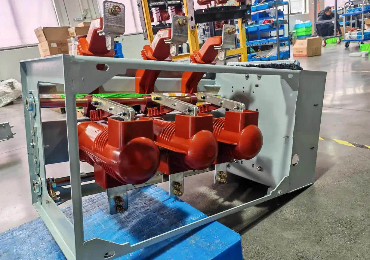
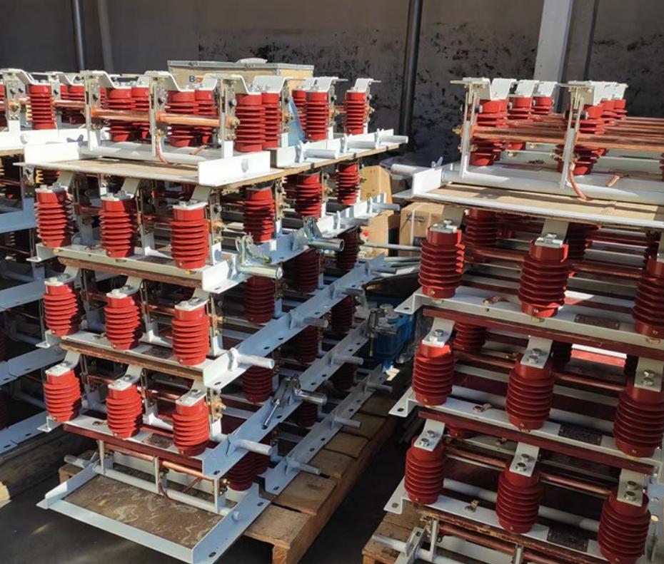
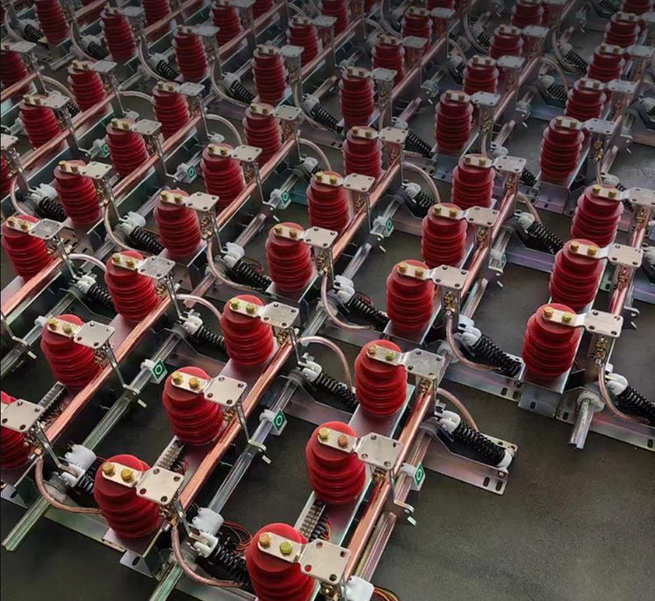
Often installed upstream with other gear like metal‑clad switchgear and 11 kV vacuum circuit breakers to keep plant power stable.
Automatic Voltage Regulators (AVR) for generators
Automatic voltage regulator AVR units keep the generator and alternator output steady under changing load.
Common in facilities with their own gensets, UPS systems, and high-power voltage regulator needs.
How these regulators fit into industrial power architectures
In a typical U.S. factory layout:
Grid/substation side
Three‑phase transformers, step‑type and feeder substation voltage regulators, and sometimes AC voltage stabilizer industrial units for power‑quality sensitive lines.
Distribution and panels
Panel‑mount or DIN‑rail industrial voltage regulators feeding control panels, drives, and machine tools.
Integration with factory power distribution regulation and protection devices.
Point‑of‑load and electronics
Switching DC‑DC converter types for the main DC bus (e.g., 48 V to 24 V / 12 V).
Linear voltage regulators industrial (including low dropout LDO regulator) for clean 5 V / 3.3 V rails on PLCs, robotics controllers, sensor networks, and automation I/O.
Every layer—substation, distribution, and point‑of‑load—uses a different voltage regulator type to balance efficiency, power level, and reliability for U.S. industrial environments.
Linear Voltage Regulators in Industrial Power Systems

How Linear Voltage Regulators Work
Linear voltage regulators keep a steady DC output by acting like a variable resistor between the input and the load. In a simple industrial voltage regulator circuit, the IC compares the output to an internal reference, then adjusts a pass transistor to hold the voltage constant, even when your input or load current shifts.
Great for PLC power supply regulators, sensors, and control boards
Common when you need to drop 24 VDC down to 12 V, 9 V, or 5 V with very low noise and ripple
Series Regulators vs Low Dropout (LDO) Regulators
Both are linear voltage regulators, but they behave differently when the input voltage gets close to the output:
Series regulators
Need a larger “headroom” (Vin must be several volts above Vout)
Simple, rugged, and ideal when you have a stable 24 V or 12 V rail
Low dropout (LDO) regulators
Work with a very small difference between input and output (hundreds of millivolts)
Perfect for battery-backed UPS voltage regulation or tight DC bus rails where you can’t afford extra voltage loss
Fixed-Output vs Adjustable Linear Regulators
Fixed voltage regulators
Pre-set outputs (5 V, 12 V, 15 V, etc.)
Easy to design in and quick to deploy in panel-mount or DIN rail power solutions
Adjustable linear regulators
Use a resistor divider to set the voltage you want
Handy when you need a custom level for robotics power supply design or mixed sensor networks
Pros of Linear Regulators in Industrial Gear
Linear voltage regulators shine where clean power and simplicity matter more than raw efficiency:
Very low noise and ripple – better for analog sensors, PLC I/O, and communication modules
Fast transient response – handles load steps from relays, solenoids, and small motors smoothly
Simple design – minimal external parts, easy to troubleshoot, easy to qualify for industrial panels
Excellent EMI behavior – no high-frequency switching, so fewer headaches with electromagnetic interference
Cons: Heat Dissipation and Efficiency Limits
The main trade-off with linear voltage regulators in industrial applications is heat:
Efficiency is roughly Vout / Vin, so dropping from 24 V to 5 V at high current wastes a lot of power as heat
Requires heatsinks, airflow, and derating, especially in sealed NEMA enclosures or hot factory floors
Poor choice for high-power voltage regulator roles feeding big DC loads or multiple drives; you’ll usually pair linear stages with upstream switching DC-DC converter types instead
If you’re already working with medium or high voltage distribution and transformers—like an oil-immersed transformer feeding your plant’s low-voltage panels—you’ll typically use linear voltage regulators at the last stage to clean up and stabilize power locally for sensitive electronics, keeping the heavy lifting and efficiency work on the upstream conversion side.
Switching Voltage Regulators: High-Efficiency Power for Industry
Core Working Principle (PWM + Energy Storage)
Switching voltage regulators don’t “burn off” extra voltage as heat like linear regulators. Instead, they rapidly switch the input on and off:
A power switch (MOSFET) is driven by PWM (pulse-width modulation)
An inductor and capacitors store and release energy
By adjusting the duty cycle, the regulator controls the average output voltage
Result: a compact, efficient voltage regulator circuit ideal for industrial panels
Common DC-DC Converter Types (Buck, Boost, Buck-Boost, SEPIC, Ćuk)
Here’s how the main DC-DC converter types fit into industrial use:
| Topology | Also Called | What It Does | Typical Industrial Use |
|---|---|---|---|
| Buck | Step-down converter | High DC to lower DC | 24 V to 5/12 V for PLC power supply regulators |
| Boost | Step-up converter | Low DC to higher DC | Battery/solar to DC bus in UPS voltage regulation |
| Buck-Boost | Inverting/non-inverting forms | Can step up or down | Loads that must stay stable with wide input swings |
| SEPIC | Single-ended primary-inductor converter | Non-inverting, step up/down | Sensors, control gear where input can go above/below output |
| Ćuk | Ćuk converter topology | Inverting, low ripple | Industrial sensor networks needing very low input/output ripple |
Step-Down vs Step-Up vs Inverting in Industrial Systems
In U.S. plants, I usually see switching regulators used like this:
Step-down (buck):
24 VDC bus → 5 V/12 V rails for industrial automation power, HMIs, PLCs
48 V → 24 V in telecom and control cabinets
Step-up (boost):
12 V battery → 24 V DC bus in UPS voltage regulation
Supporting long cable runs where voltage drops are an issue
Inverting (buck-boost/Ćuk):
Generate negative rails (e.g., -12 V) for analog and instrumentation
Specialized industrial voltage regulators for sensors and measurement
Benefits of Switching Voltage Regulators in Industry
For modern industrial-grade power solutions, switching regulators are often the default because they deliver:
High efficiency (often 90%+), even at high load current
Small size and lighter heatsinks vs. linear voltage regulators in industrial setups
Wide input voltage range to ride through voltage sag and surge events
Flexible buck converter, step-down, boost converter, step-up, and buck-boost converter applications in one architecture
High-efficiency switching stages also help reduce overall industrial power quality issues and stress on upstream protection like surge arresters, which we cover in detail in our guide on the differences between lightning and surge arresters.
Drawbacks: EMI, Layout, and Filtering
The trade-offs with switching voltage regulators:
EMI noise: Fast switching edges create electromagnetic interference (EMI) that can affect PLCs, sensors, and communication lines
Layout-sensitive: PCB layout, grounding, and loop areas are critical; bad layout = radiated and conducted noise
Filtering needs: Extra inductors, capacitors, and sometimes common-mode chokes are needed to meet industrial EMC and protect sensitive loads
More complex design: Compared to a fixed voltage regulator IC, a full switching regulator design needs more components and careful testing
Used correctly, though, switching industrial voltage regulators gives you the best mix of efficiency, power density, and flexibility for U.S. factories, panels, and automation lines.

Linear vs Switching Voltage Regulators in Industry
Choosing between linear voltage regulators and switching voltage regulators is one of the most important power decisions in any industrial panel, PLC cabinet, or control system. Here’s how I look at it in real plant conditions.
Efficiency and Thermal Management
Linear voltage regulators
Great when the input and output voltages are close.
Efficiency ≈ Vout / Vin, so dropping 24 V to 5 V at a few amps becomes a heater.
Need solid thermal management: big heatsinks, airflow, derating, and good cabinet layout.
Switching voltage regulators
Typical efficiency: 85–95%, even with large input–output differences.
Much lower heat for the same load current, which helps panel temperatures, reliability, and overall industrial power efficiency.
Rule of thumb:
Below ~1 W loss and small voltage drop: linear is fine.
Above that, or with 24 V → 5 V / 3.3 V at higher current: go switching.
Noise, Ripple, and EMI Performance
Linear regulators
Very low noise and ripple, high PSRR.
Ideal for sensors, analog inputs, instrumentation, PLC analog cards, and communication interfaces.
Often used as a “clean-up” LDO after a switching DC-DC converter.
Switching regulators
Higher ripple and EMI by nature of PWM and fast switching edges.
Need careful PCB layout, shielding, filters, and grounding to avoid interference with sensitive electronics, especially around long cable runs and high-power gear like VFDs and auto-reclosers in medium-voltage systems.
Cost, Board Space, and Component Count
Linear regulators
Cheap ICs, very simple voltage regulator circuit (regulator IC + a couple of caps).
But at high power, they need big heatsinks, which increase cost and take up panel space.
Switching regulators
ICs and magnetics cost more, and the component count is higher.
For higher current and wide input range, the total system cost is usually lower once you factor in smaller heatsinks, reduced energy loss, and higher reliability in hot enclosures.
When to Use Linear vs Switching in Industrial Use Cases
Use a linear voltage regulator when:
You need quiet, low-noise power for:
4–20 mA sensors
Analog measurement modules
Data acquisition, PLC I/O, industrial Ethernet, serial buses
The voltage drop is small (for example, 12 V → 9 V or 5 V → 3.3 V).
Load current is low to moderate (tens to a few hundred mA).
You want a simple, rugged, fast-response voltage regulator circuit without a complicated design.
Use a switching voltage regulator when:
You’re stepping 24 V DC down to 12 V / 5 V / 3.3 V at high current for:
PLC backplanes and control panels
Industrial PCs, HMIs, edge gateways
Robotics, motion control, and servo drives logic supplies
You’re feeding DC buses for drives, UPS systems, and distributed power rails.
You need high efficiency, small size, and better thermal performance in sealed or hot cabinets.
Energy cost and panel temperature are critical factors over system's lifetime.
Quick Decision Matrix: Linear vs Switching
| Condition / Priority | Best Choice |
|---|---|
| Load current < 200–300 mA, small V drop | Linear regulator |
| High current or big Vin–Vout difference | Switching regulator |
| Ultra-low noise / sensitive analog circuits | Linear or LDO |
| Cabinet heat and efficiency are critical | Switching regulator |
| Minimal design time and parts count | Linear regulator |
| Wide input range / unstable bus | Switching regulator |
In practice, most solid industrial power supply stability strategies use both: a switching regulator for bulk efficiency and one or more LDO linear regulators downstream to clean up the rails for sensitive loads.
Industrial Use Cases for Voltage Regulators
Voltage regulation in plant power distribution and three-phase networks
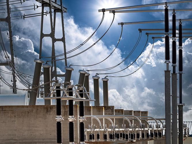
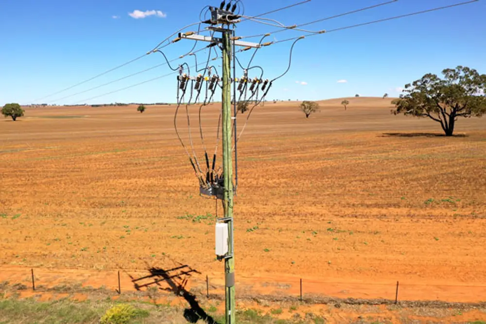
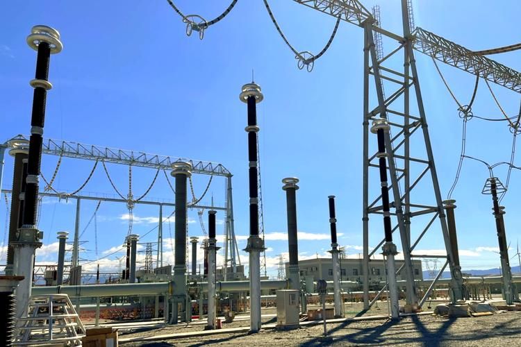
In U.S. plants, industrial voltage regulators are key to keeping three-phase distribution stable when the utility sags, surges, or goes unbalanced. On the medium-voltage side, high-power voltage regulators, three-phase voltage stabilizers, and step-type voltage regulators keep bus voltages inside tight limits so downstream drives, PLCs, and controls don’t trip. Paired with proper transformers and surge protection—like a 10 kV high-voltage setup that might include dedicated high-voltage equipment and accessories—you get a much more resilient plant power backbone.
Regulators for PLCs, control panels, and automation systems
PLCs, I/O racks, and panel PCs expect clean 24 VDC or 5 VDC power. Here we typically use a DIN-rail switching regulator to drop from 480/277 VAC or 120 VAC to 24 VDC, then linear voltage regulators or LDOs on the board for low-noise rails (5 V, 3.3 V, 1.8 V). A solid PLC power supply regulator strategy prevents nuisance trips, random resets, and corrupted data in control panels and industrial automation systems.
Motor drives, VFDs, inverters, and servo systems
VFDs, soft starters, and servo drives rely on a steady DC bus voltage and controlled AC output. Inside these systems, DC-DC converter types (buck, boost, buck-boost) stabilize control logic, gate drivers, and feedback circuits, while external AC voltage stabilizers and generator AVRs protect against big swings at the input. Proper motor drive voltage control and VFD voltage regulation cut downtime from overvoltage trips and extend motor life.
Robots, sensors, and field instrumentation
Robots, cobots, safety scanners, and sensor networks all need regulated low-voltage DC (typically 24 VDC down to logic-level rails). We usually combine a robust industrial switching supply with point-of-load LDO regulators on the robot or sensor boards. Clean sensor network voltage regulation keeps analog measurements accurate and avoids flaky behavior in encoders, proximity switches, and transmitters spread across the factory floor.
UPS, backup power, and DC bus stabilization
In U.S. plants with high automation, UPS voltage regulation is non-negotiable for servers, SCADA, and critical PLCs. Line-interactive or online UPS systems use automatic voltage regulators (AVR) to correct sags and surges without draining batteries, while DC-DC converters stabilize DC buses feeding drives and controls. A well-tuned, regulated DC bus in industry stops nuisance trips during brownouts and supports smooth generator or backup source transfers.
Harsh environment voltage regulation challenges
In harsh industrial environments—heat, dust, vibration, and electrical noise—regulators face:
High ambient temperature → derating, forced cooling, and larger heatsinks
Heavy EMI and harmonics from large drives and welders
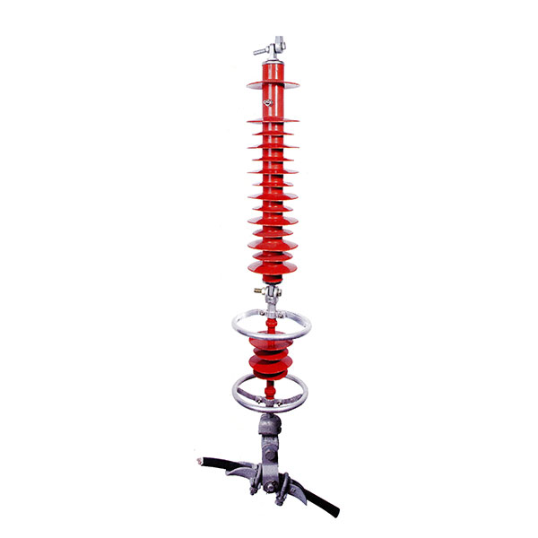
Frequent surges and lightning events, where upstream protection like a rugged lightning arrester for industrial lines is essential
Mechanical stress on panel-mounted and PCB-mounted regulators
Here we lean on ruggedized voltage regulators, wider thermal ratings, conformal coating, and good panel layout.
Real-world failure examples from poor voltage regulation
Common problems U.S. plants see from weak or wrong voltage regulator choices:
VFDs and servo drives tripping during voltage sags, stopping production lines
PLCs and HMIs randomly rebooting because 24 V rails dip under load
Overheated linear regulators are causing drift in instrumentation and false alarms
Motor insulation damage and premature failure from chronic overvoltage
UPS systems cycling on and off due to unstable input, shortening battery life
Tight, well-engineered industrial voltage regulation directly cuts plant downtime, protects high-value gear, and stabilizes production quality.
Specialized Industrial Voltage Regulators
When you get into higher power and tougher environments, you move past basic DC-DC converters and into specialized industrial voltage regulators. These are what keep plant power stable when generators, feeders, or whole lines are swinging around.
Automatic Voltage Regulator (AVR) for Generators
An automatic voltage regulator (AVR) is the brain behind a generator or alternator’s output:
Senses the generator output voltage in real time
Adjusts the field excitation to keep the voltage constant under changing load
Handles voltage sag, surge, and power factor swings
Critical for backup generators, standby power, and industrial microgrids
For plants with heavy motor loads, a solid generator voltage regulator is what stops lights from dimming and drives tripping every time a big motor starts.
Servo and Electromechanical Voltage Stabilizers
A servo voltage regulator (servo stabilizer) uses a motor-driven variac (variable transformer):
Wide input range, typically ±20–30% variation handling
Smooth, stepless output voltage correction
Good for three-phase voltage stabilizer applications like CNC lines, process equipment, and mixed lighting + motor loads
Electromechanical units are slower than electronic AVRs, but they’re simple, rugged, and easy to service—something many US maintenance teams still prefer in older plants.
Ferroresonant Constant Voltage Transformers
A ferroresonant transformer (constant voltage transformer, CVT) is built for brutal conditions:
Naturally regulates output with a saturating core and resonant capacitor
Excellent isolation from line noise, spikes, and surges
Handles rugged loads like welders, contactor-heavy panels, and dirty industrial feeders
Keeps running even with distorted waveforms and frequent voltage dips
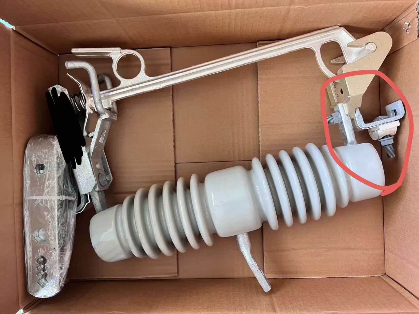
If your plant has frequent grid disturbances or relies on outdoor equipment with fuse and switchgear protection (for example, combined with gear like an outdoor SF6 load break switch for feeder switching), a ferroresonant solution adds a strong buffer against power quality issues.
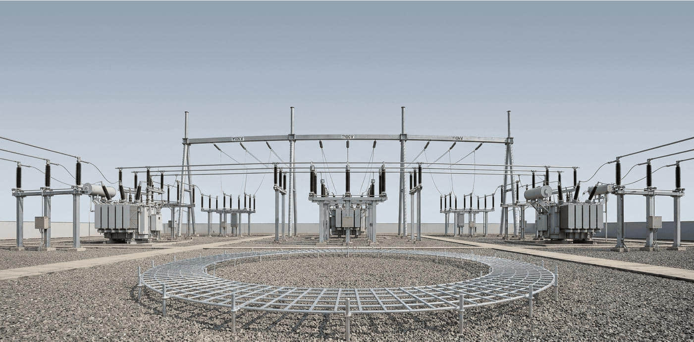
High-Power Step-Type Voltage Regulators
For feeders, substations, and medium-voltage distribution, plants, and utilities use step-type voltage regulators:
Tap-changing transformers that “step” the output voltage up or down
Used in substation voltage regulator setups and long feeder lines
Designed for high power voltage regulator duty: hundreds of kVA up into the MVA range
Keep bus voltage within tight limits as feeder loading changes across a shift
These are the backbone of factory power distribution regulation, especially where long runs and large motors cause big voltage drops.

Choosing AVR vs Servo vs Ferroresonant
Here’s a quick way to narrow it down:
Electronic AVR
Best for: Generators, alternators, UPS, dynamic loads
Pros: Fast, compact, efficient, modern communication options
Use when you need tight regulation and quick response.
Servo Voltage Regulator
Best for: Whole panels, three-phase equipment, mixed industrial loads
Pros: Wide correction range, cost-effective for medium to high kVA
Use when input swings are big but not lightning-fast.
Ferroresonant CVT
Best for: Rugged loads and harsh environments with lots of spikes and sags
Pros: Excellent isolation, ride-through, and noise filtering
Use when reliability and power conditioning matter more than perfect efficiency or size.
In most US plants, we end up with a mix: AVR on generators, servo stabilizers on critical panels, and ferroresonant transformers in the nastiest spots where electronics keep dying from bad power.
Selecting the Right Voltage Regulator for Industrial Applications
Choosing the right voltage regulator for an industrial application starts with the basics: know your power, your load, and your environment. From there, you can narrow down the right voltage regulator types and voltage regulator circuits that actually hold up on a factory floor.
Key Selection Factors for Industrial Voltage Regulators
When I size a regulator for an industrial panel or skid, I always lock in these points first:
Power level
Input voltage range (e.g., 208/240/480 VAC, 24/48 VDC bus)
Output voltage and current (continuous + peak)
Headroom for inrush and motor starts (typically +25–50% margin)
Input variation
How bad are sags, surges, and brownouts?
Single-phase vs three-phase, balanced vs unbalanced
Need for overvoltage protection and ride-through capability
Load type
Constant DC load, pulsed load, or highly dynamic (motors, VFDs, servos)
Sensitive electronics (PLCs, sensors, controllers) vs heavy industrial loads
Need for low noise and ripple performance or just “rugged and stable”
Efficiency and thermal
Linear vs switching voltage regulators efficiency at your actual load
Panel temperature, enclosure size, airflow, and derating needs
Heatsink and fan allowance inside the cabinet
Environment
Ambient temp, dust, oil mist, vibration, and humidity
Indoor MCC vs outdoor substation vs harsh process area
Need for ruggedized industrial voltage regulators or conformal coating
Step-by-Step Sizing and Selection Workflow
Use this simple workflow so you don’t miss anything:
Define input and output
Min/max input voltage, frequency (for AC), or DC bus range
Required output voltage(s) and max load current per rail
Choose linear vs switching type
Higher current, wide input variation, or high efficiency requirements
Low-current, noise-sensitive PLC, sensor, and instrumentation rails
Use linear voltage regulators or LDOs for:
Use switching DC-DC converters (buck, boost, buck-boost) for:
Check thermal and efficiency
Linear: (Vin – Vout) × Iout
Switching: Pout / η – Pout
Estimate losses:
Make sure cabinet temperature and heatsink space can handle it
Verify protection and standards
Overvoltage, undervoltage, short-circuit, over-temp
Industrial ratings, UL/cUL, and IEC where required
Match form factor
DIN rail power supply regulator vs panel mount voltage regulator
Space available in the existing panel or cabinet
Validate with real-world conditions
Consider worst-case line dips, motor starts, and fault events
Run a quick load profile instead of designing for “average” current
For higher-power distribution or feeder-level regulation, I often pair regulators with an appropriately sized transformer. A lot of US plants use a substation transformer with on-load tap changer to stabilize upstream voltage before it even reaches the regulators; you can see how that works in a typical on-load tap-changer substation transformer setup.
Common Mistakes When Choosing Industrial Voltage Regulators
I see the same errors over and over in US plants:
Underestimating inrush and peak loads
Motors, VFDs, solenoids, and relay banks can crush a regulator sized only for “nominal” current.Ignoring ambient temperature
A regulator that’s fine at 25°C on paper overheats in a 45–50°C sealed cabinet.Using linear regulators where switching is required
At higher currents, heat dissipation becomes unmanageable and kills reliability.Skipping EMI and grounding planning
Especially with switching regulators near drives, inverters, and welders.No margin for future expansion
Panels get upgraded; give yourself 20–30% current headroom from day one.
Best Practices for Panel and Cabinet Integration
To keep your industrial power supply stability high and downtime low, build regulators into your panels the right way:
Layout and wiring
Keep high-current switching paths short and tight
Separate noisy power wiring from sensitive signal lines
Star-ground or single-point ground strategy where possible
Thermal management
Mount regulators and power supplies where convection works for you, not against you
Use proper heatsinks, ventilation, and, if needed, forced airflow
Apply derating based on real cabinet temperature, not lab numbers
Protection and coordination
Add fuses or breakers sized for both the regulator and downstream loads
Use surge protection and proper MOV/TVS placement for industrial power quality issues
Serviceability
Leave clear access to terminals and adjustment points
Label each voltage regulator circuit, breaker, and disconnect clearly
Keep documentation in the panel for quick industrial power troubleshooting
If you’re planning a new line or upgrading a section of a plant, it’s smart to align your regulators with your upstream medium-voltage gear. When we design around custom MV switchgear solutions, we size the downstream regulators with the same mindset: worst-case utility events, motor starts, and selective coordination. That’s the kind of thinking you see in well-designed MV switchgear and distribution setups.
Maintenance and Troubleshooting of Voltage Regulators

Keeping industrial voltage regulators healthy is non‑negotiable if you want stable production and minimal downtime. Here’s how I look at maintenance, troubleshooting, and smart upgrades in real plants.
Typical Signs of Regulator Stress or Failure
Watch for these early clues your industrial voltage regulator is in trouble:
Frequent nuisance trips on breakers or protection relays
Overheating housings or heatsinks (too hot to touch for more than a second)
Output voltage drift outside spec, especially under load swings
Visible discoloration or smell of burnt epoxy/plastic around power devices
Increased noise and ripple on the DC bus (affecting PLCs, VFDs, and sensors)
Random controller resets or communication dropouts from PLC power supply regulators
Unexpected wear on motors or drives due to poor VFD voltage regulation
If you’re already dealing with fuse issues or unexplained trips, case studies like this analysis of a PT cabinet fuse burnout in a substation environment show how upstream faults and poor regulation can cascade through a system: PT cabinet fuse burnout case studies and solutions.
Routine Inspection, Testing, and Monitoring
For industrial voltage regulators (linear, switching, AVRs, and three‑phase stabilizers), I’d put these checks on the maintenance schedule:
Visual checks (monthly/quarterly)
Look for dust buildup, loose terminals, corrosion, and swollen capacitors
Confirm fans spin freely and filters aren’t clogged
Electrical tests (quarterly/annually)
Measure input/output voltage, line regulation vs load regulation, and check for excessive ripple
Use a scope to check switching noise and EMI on DC‑DC converter types (buck, boost, buck‑boost)
Verify protection functions: overvoltage, undervoltage, overcurrent, thermal shutdown
Continuous or periodic monitoring
Log temperature, load current, and output voltage through SCADA or digital regulator interfaces
Set alarms for voltage sag/surge and over‑temperature events
Thermal Management: Heatsinks, Airflow, and Derating
Most failures in high-power voltage regulators come back to heat. For panel‑mount and DIN rail voltage regulators, I always focus on:
Heatsink sizing:
Check device datasheets and size heatsinks for worst‑case ambient (often 40–50°C in US factory panels)
Add thermal interface material and tighten hardware correctly
Airflow planning:
Keep intake at the bottom, exhaust at the top, and leave space around regulators
Avoid mounting hot devices (VFDs, soft starters) directly under sensitive switching regulators
Derating in real life:
Run linear voltage regulators below 70–80% of rated current, especially with high input‑to‑output differences
Derate switching voltage regulators for high ambient temperatures, continuous full load, and dusty environments
For harsh environments, prefer ruggedized, industrial‑grade power solutions with documented derating curves
Upgrading Legacy Voltage Regulation Systems
If you’re still running old electromechanical or oversized legacy units, upgrading usually pays for itself in efficiency and uptime:
Know your actual load and profile
Measure peak, average, and inrush current on each feeder or DC bus
Check how often voltage sag, surge, or imbalance occurs on your factory power distribution system
Targeted replacements
Replace aging linear voltage regulators feeding PLCs and robots with modern high‑efficiency DC‑DC regulators
Swap old, slow AC voltage stabilizers with fast electronic AVRs or digital three‑phase voltage stabilizers on critical lines
Improve coordination with protection and switchgear
Make sure new regulators play well with your switchgear and protection schemes so faults are isolated cleanly; this is critical in systems using advanced switchgear protection strategies similar to those described here: electrical switchgear protection in industrial systems.
Plan for diagnostics and data
Choose regulators with digital monitoring, Modbus/Ethernet, or built‑in logging for predictive maintenance
Standardize on a few regulator families for easier spares and faster troubleshooting
If you build maintenance around these basics—early stress detection, scheduled testing, solid thermal management, and smart upgrades—your industrial voltage regulators will stay stable, efficient, and far less likely to cause plant downtime.
Future Trends in Industrial Voltage Regulation

Smart, digital, and IoT-enabled voltage regulators
Industrial voltage regulators are going fully digital. In U.S. plants, I’m seeing most new voltage regulator types ship with:
Digital control ICs and microcontrollers for tighter voltage accuracy
Remote monitoring over Ethernet/Modbus/TCP, so maintenance doesn’t have to open panels
IoT-enabled voltage regulators that report:
Input/output voltage and current
Temperature and efficiency
Alarms for overvoltage, undervoltage, and overload
These “smart” voltage regulator circuits plug into existing industrial automation and SCADA, just like your contactors or high-voltage disconnect switches, making factory power supply stability much easier to manage across multiple lines and buildings.
SiC and GaN for high-efficiency industrial regulators
For high-power industrial voltage regulators, silicon carbide (SiC) and gallium nitride (GaN) devices are changing the game:
Higher efficiency DC-DC converter types (buck, boost, buck-boost) at high power
Smaller heatsinks and cabinets, thanks to lower heat dissipation
Higher switching frequency, which shrinks inductors and capacitors
Better performance in harsh environments and high-temperature panels
You’ll see SiC and GaN first in UPS voltage regulation, VFD voltage regulation, DC bus converters, and substation-level high power voltage regulators, where energy savings and footprint directly impact operating cost.
Predictive maintenance and data-driven health monitoring
The next step is making industrial voltage regulators self-report their health before they fail:
Continuous tracking of temperature, ripple, duty cycle, and startup behavior
Analytics that flag:
Rising operating temperature (blocked airflow, dirty filters)
Increased noise and ripple (aging capacitors)
Abnormal line regulation vs load regulation behavior
Integration with CMMS and plant dashboards so teams can schedule planned shutdowns, not emergency repairs
By adding smart measurement to voltage regulators the same way we already do for protection devices and fuses (for example, when reviewing fault paths and coordination similar to what you’d consider in industrial fuse selection), plants in the U.S. can cut downtime, extend equipment life, and keep power quality tight across their entire factory power distribution.
FAQs on Industrial Voltage Regulators
Best voltage regulators for high‑power motors and VFD systems
For large motors, variable frequency drives (VFDs), and heavy process loads, I usually look at:
Automatic Voltage Regulators (AVR) on the generator or main feeder to keep the AC bus stable.
Three‑phase servo voltage regulators or step‑type voltage regulators on the distribution side when you’re dealing with frequent sags and swells.
High‑power DC‑DC converters (usually switching buck or buck‑boost) on the DC bus that feed drives, PLCs, and 24 V control power.
Key checks for high‑power motor and VFD voltage regulator selection:
Motor inrush current and VFD start‑up current
Voltage sag/surge levels on your plant bus
Harmonic currents from the VFDs (THD)
Coordination with upstream protection and any oil-immersed transformers feeding the line
For US plants with 480 V or 600 V systems, I recommend industrial‑grade, UL‑listed three‑phase regulators sized with at least 125–150% margin over the maximum continuous VFD load.
How LDO regulators behave in noisy industrial environments
Low dropout (LDO) linear regulators are great for quiet, low‑ripple rails, but in industrial environments, you have to treat them carefully:
LDOs do not fix big spikes or deep sags on their own—put them after a robust DC‑DC converter or filtered DC bus.
Many modern LDO voltage regulator ICs have good power supply rejection ratio (PSRR) in the audio to low‑MHz range, which helps clean up switching noise from DC‑DC converters and VFD control electronics.
Layout matters:
Keep input/output caps close to the LDO pins
Use solid ground planes
Shield sensitive traces from high‑dv/dt motor drive wiring
I use LDO regulators mainly to clean up a 5 V or 3.3 V rail for sensors, PLC I/O, and industrial Ethernet, where noise and ripple performance really matters.
Choosing regulators for three‑phase and unbalanced loads
For three‑phase industrial voltage regulators, the big question is how often you see unbalanced loads (single‑phase loads pulled off a three‑phase system):
For balanced, mostly motor loads:
Automatic Voltage Regulators (AVR) on generators
Three‑phase tap‑changing or step‑type voltage regulators on feeders and substations
For mixed or heavily unbalanced loads:
Independent phase‑control servo stabilizers that sense and correct each phase separately
Robust three‑phase voltage stabilizers with good handling of neutral shifts and phase imbalance
When I size a three‑phase industrial voltage regulator for US plants (208/120 V, 480 V, or 600 V systems), I check:
Maximum expected single‑phase loading on any leg
Neutral current and neutral conductor size
Compatibility with upstream substation or box‑type substation gear, like a mobile substation used in harsh sites.
If your plant has lots of single‑phase office loads mixed with big three‑phase drives, you need a regulator explicitly rated for unbalanced operation.
Dealing with EMI and harmonics in switching regulator designs
Switching voltage regulators (buck, boost, buck‑boost, SEPIC, Ćuk) are efficient, but they bring EMI and harmonics you can’t ignore in industrial automation power:
At the regulator level:
Use proper input and output LC filters
Keep switching loop areas tight and use short, wide traces
Add snubbers or spread‑spectrum switching where supported
Use shielded inductors and grounded heat sinks
At the system level:
Isolate noisy DC‑DC stages from sensitive PLCs, sensors, and communication lines
Separate grounding for power and signal, tied at a single reference point
Use line filters and harmonic mitigation if your DC‑DC stages feed back into AC mains
Good switching voltage regulator design dramatically cuts EMI, ripple, and harmonics, which means fewer nuisance trips on PLCs, less interference with the fieldbus, and lower risk of plant downtime from power quality issues.