Introduction: From Current Transformer Ratio to Voltage Transformer Ratio
In the previous article, we explained how to calculate the current transformer ratio. Now let’s move straight to the next field question electricians and relay technicians ask most often: how do you calculate the ratio of a voltage transformer?
The answer is direct: voltage transformer ratio = primary rated voltage ÷ secondary rated voltage. For example, if a voltage transformer is rated 10kV/100V, then the ratio is 100:1.
If you read this article to the end, you will know not only voltage transformer ratio calculation, but also how to verify it on site, how to avoid relay setting mistakes, and how to apply the same practical logic to a 3150kVA transformer differential protection setup without drowning in theory.
The Fast Answer: Voltage Transformer Ratio Formula and One-Minute Example
Core formula:
VT ratio = primary voltage / secondary voltage
Example:
A potential transformer nameplate shows 10,000V / 100V.
So:
VT ratio = 10,000 / 100 = 100
That means the instrument transformer turns ratio formula, in practical voltage terms, is expressed as 100:1.
Another quick example:
11kV / 110V = 11,000 / 110 = 100:1
This is the shortest correct answer for most search queries about how to determine the ratio of a voltage transformer.
What Is a Voltage Transformer Ratio and Why Does It Matter in Real Projects
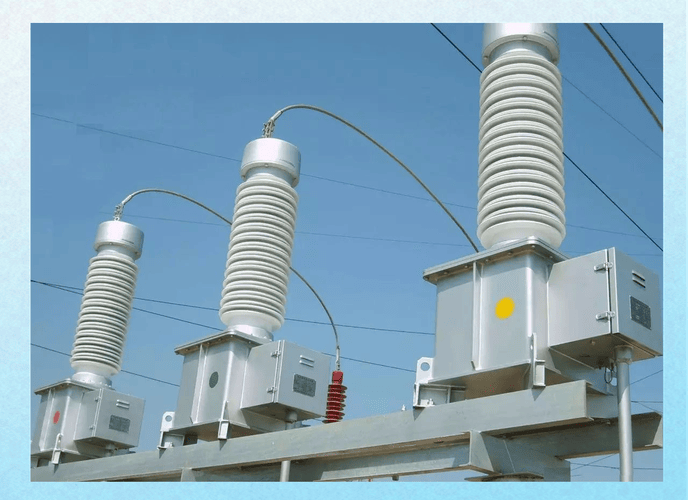
A voltage transformer, also called a potential transformer, reduces medium or high voltage to a safe low value for metering, protection, relay input, synchronizing, and power quality monitoring.
The ratio matters because the relay, energy meter, multifunction meter, and SCADA analog input all assume a specific scaling relationship. If that ratio is wrong in design, procurement, installation, or relay parameter entry, every downstream value becomes wrong too.
In real projects, I have seen three expensive consequences from ratio mistakes:
Energy billing deviation even when the transformer itself was healthy
Relay under-voltage or over-voltage logic operating at the wrong thresholds
Differential and directional protection behavior is becoming misleading because the voltage reference scaling was entered on the wrong base
So the ratio is not just a formula for exams. It directly affects whether a panel is accepted, whether a protection system is trusted, and whether a plant handover goes smoothly.

Voltage Transformer Ratio Calculation Formula Explained Step by Step
At the basic level, primary and secondary voltage ratio measurement follows the rated relationship between the high-voltage winding and the low-voltage winding.
In ideal form:
Voltage ratio = Primary voltage / Secondary voltage = Primary turns / Secondary turns
This is why many technicians also refer to it as the instrument transformer turns ratio formula, even though in field work, we usually calculate with nameplate voltage values instead of counting turns.
Rated Ratio vs Actual Measured Ratio
Rated ratio is the nameplate value provided by the manufacturer, such as 11kV/110V.
The actual measured ratio is what you obtain during commissioning or maintenance by applying a known voltage and measuring the secondary output.
These two should be close within the allowed tolerance defined by the applicable product standard, accuracy class, test condition, and burden. If not, the problem may be the transformer, the test method, the burden, or even the wiring itself.
How Turns Ratio Relates to Voltage Ratio
For an ideal transformer, the voltage ratio follows the turns ratio directly. If the primary winding has 100 times more turns than the secondary winding, the primary voltage will be 100 times the secondary voltage.
In practice, things are slightly less perfect because of winding resistance, leakage reactance, magnetizing current, burden, and measurement error. That is why serious acceptance work never stops at just reading the nameplate.
How to Convert Line-to-Line and Phase-to-Neutral Values Correctly

This is one of the biggest field traps.
If the nameplate or drawing gives a line-to-line primary voltage, but your secondary is measured phase-to-neutral, you cannot compare them directly without converting to the same base.
For a three-phase system:
Line-to-line voltage = phase voltage × √3
Phase voltage = line-to-line voltage ÷ √3
For example, if a system is 11kV line-to-line, the phase-to-neutral voltage is approximately 6.35kV. If the PT secondary is 110V/√3 per phase and you compare that incorrectly with 110V line voltage, your relay scaling will be off by 73.2%.
I have seen this exact mistake during commissioning reviews more than once, especially when the protection engineer, switchgear vendor, and site technician were each using different voltage bases in their own documents.
Voltage Transformer Ratio Calculation Examples With Real Numbers
Let’s use practical nameplates that appear frequently in industrial and utility projects.
Example 1: 11kV to 110V Potential Transformer Ratio
Nameplate: 11,000V / 110V
Calculation:
11,000 ÷ 110 = 100
So the potential transformer ratio is 100:1.
This is common in medium-voltage metering and protection panels.
Example 2: 6.6kV to 100V Voltage Transformer Ratio
Nameplate: 6,600V / 100V
Calculation:
6,600 ÷ 100 = 66
So the VT ratio is 66:1.
Many legacy plant systems still use 6.6kV distribution, especially in older industrial facilities, marine installations, and retrofit process plants. The label may differ, but the math is the same.
Example 3: 33kV to 110V Ratio for Utility Metering
Nameplate: 33,000V / 110V
Calculation:
33,000 ÷ 110 = 300
So the ratio is 300:1.
At this ratio level, acceptance testing becomes more sensitive because small absolute errors on the secondary side can represent meaningful primary scaling deviation in utility metering or grid protection applications.

Common Field Mistakes When Determining Voltage Transformer Ratio
Most wrong answers in the field do not come from bad mathematics. They come from wrong assumptions, wrong measurement base, or wrong interpretation of the circuit.
Confusing Voltage Transformer Ratio With Current Transformer Ratio
A CT ratio and a VT ratio are not calculated the same way in practice.
For a CT, you usually think in terms of primary current/secondary current, such as 250/5. For a VT, you think in terms of primary voltage / secondary voltage, such as 11kV/110V.
The dangerous mistake is copying CT-style relay scaling habits into VT settings without checking whether the relay expects actual voltage, per-unit value, line voltage, or phase voltage.
Using System Nominal Voltage Instead of Nameplate Primary Voltage
This happens constantly during panel handover.
A technician sees a plant called “10kV system” and assumes the PT is 10kV/100V, but the actual nameplate may be 11kV/110V or 10.5kV/110V. That difference may look small, but it can shift meter scaling and relay thresholds enough to trigger acceptance disputes.
Always calculate from the actual nameplate primary voltage, not from a verbal system label.
Ignoring Burden and Accuracy Class During Testing
This is where many superficial articles stop too early.
A transformer can have the correct nominal ratio and still perform poorly under actual connected load. The reason is burden. If the connected meters, relays, transducers, cable resistance, and terminal contacts exceed what the PT was designed to supply, the measured secondary voltage can sag or distort.
That is why the voltage transformer accuracy class and burden must always be checked together.
Misreading Open-Delta, Phase Voltage, or Residual Voltage Connections
Wiring arrangement changes what should be measured.
In open-delta or residual voltage circuits, technicians sometimes compare a residual output with a phase-to-phase rated value and conclude the PT ratio is wrong. It is not wrong. The measurement point is different.
Always confirm:
Are you measuring phase-to-phase or phase-to-neutral?
Are you on the metering secondary or residual winding?
Is the circuit fused, open, or grounded at one point only?
Is the drawing showing the actual site wiring revision or an earlier issue?
How to Test Potential Transformer Ratio in the Field
If you want a usable answer to how to test a potential transformer ratio, keep it practical: verify safety, apply a known voltage in a controlled way, measure the output, calculate deviation, and judge against the required accuracy and burden condition.
Pre-Test Safety Checks Before Applying Any Voltage
Before any test, isolate the circuit properly.
Confirm the primary side is de-energized or under controlled test conditions
Verify lockout and tagout status
Check primary and secondary fuses
Confirm the secondary grounding point is correct and singular where required
Inspect terminal numbering against drawings
Check for loose links, burned fuse holders, and moisture entry
One of the most overlooked problems in field testing is secondary terminals that were tightened during factory assembly but loosened slightly after transport vibration. The resulting unstable contact resistance can make the measured output drift enough to send a team in the wrong diagnostic direction.
Primary Injection vs Secondary Verification Methods
There are two common approaches.
Primary injection means applying a known voltage to the primary and measuring the secondary response. This better reflects the real transformer behavior, but on medium-voltage equipment, it requires stricter safety control, suitable test equipment, and often staged energization procedures.
Secondary verification usually means checking wiring, terminal continuity, relay scaling, and expected ratio logic using secondary-side methods or a relay test set. This is safer and faster for panel checks, but it does not fully replace primary-side ratio confirmation when acceptance quality matters.
In actual commissioning, the best sequence is often:
1. Nameplate and drawing check
2. Secondary circuit verification
3. Insulation and continuity checks
4. Controlled ratio verification under known conditions
5. Relay/meter scaling confirmation
How to Record Measured Voltage and Calculate Deviation
The field method is simple.
Record:
Nameplate primary voltage
Nameplate secondary voltage
Calculated ratio
Actual applied voltage
Actual measured secondary voltage
Then calculate the expected secondary voltage:
Expected secondary voltage = Applied primary voltage ÷ Rated ratio
Deviation percentage:
Deviation % = (Measured secondary - Expected secondary) ÷ Expected secondary × 100%
For example, if the PT ratio is 100:1, and you apply 1,000V to the primary, the expected secondary is 10V. If measured secondary is 9.92V, then:
Deviation % = (9.92 - 10.00) ÷ 10.00 × 100% = -0.8%
Now you compare that result with the applicable acceptance criteria, test condition, and burden condition.
What Test Instruments Are Commonly Used On Site
The most common tools are:
Ratio tester
True-RMS multimeter
Relay test set
Secondary injection source
Insulation resistance tester
Clamp meter for supporting checks
In modern substations, the ratio tester is convenient, but experienced site engineers still rely heavily on a disciplined multimeter-and-drawing workflow. Many “transformer problems” are solved before the specialized tester is even unpacked.

Voltage Transformer Ratio Test Table for Quick Field Use
Below is a practical table format I recommend for site records. It prevents the most common handover mistake: writing down measured voltage without documenting burden, expected output, or pass/fail logic.
| Nameplate Primary Voltage | Nameplate Secondary Voltage | Calculated Ratio | Applied Primary Voltage | Measured Secondary Voltage | Deviation % | Burden | Pass/Fail |
|---|---|---|---|---|---|---|---|
| 11,000V | 110V | 100:1 | 1,100V | 11.02V | +0.18% | 25VA | Pass |
| 6,600V | 100V | 66:1 | 660V | 9.95V | -0.50% | 15VA | Pass |
| 33,000V | 110V | 300:1 | 3,300V | 10.89V | -1.00% | 50VA | Review |
Voltage Transformer Accuracy Class and Burden: Why Ratio Alone Is Not Enough
In real power systems, a correct ratio by itself is not enough.
If the voltage transformer accuracy class and burden are not suitable, you can still get poor metering results, unstable relay values, or unexplained discrepancies between panel instruments.
Typical Accuracy Classes Used for Metering and Protection
Under IEC practice, common metering accuracy classes include values such as 0.1, 0.2, 0.5, and 1.0. Protection-related classes may include forms such as 3P or 6P, depending on transformer type and application context.
Under IEEE-oriented practice, performance is expressed differently, but the core point is the same: ratio error and phase error must remain within specified limits under defined burden and operating conditions.
For buyers, the lesson is simple: never ask only for the ratio. Ask for ratio + accuracy class + burden + insulation level + standard compliance.
How Burden Changes Secondary Voltage Performance
Burden is the load connected to the PT secondary, usually expressed in VA.
If the burden is too high, the secondary voltage may no longer hold the expected value within the stated accuracy class. Long cable runs, undersized wiring, too many parallel devices, and poor terminal contact all contribute.
A practical example from field audits: a metering PT looked inaccurate during acceptance. The transformer was blamed first. But after tracing the circuit, the real issue was 80 meters of secondary cable routed through multiple marshalling terminals, plus two additional meters added late in the project without recalculating the total burden.
The PT was healthy. The design control was not.
When a Ratio Error Is Actually a Wiring or Burden Problem
You should suspect a wiring or burden issue when:
The nameplate and factory report are normal
Bench test is acceptable
Field deviation changes when loads are disconnected
Different instruments show different voltages on the same secondary circuit
Terminal temperatures or contact conditions look suspicious
This distinction matters because replacing the PT will not solve a bad secondary network.
IEEE and IEC Requirements That Influence Voltage Transformer Ratio Verification
For authority and real project credibility, ratio verification should be aligned with recognized standards, not personal guesswork.
IEC Framework for Inductive Voltage Transformers
For inductive voltage transformers, the IEC 61869 framework is highly relevant, especially IEC 61869-1 for general requirements and IEC 61869-3 for additional requirements for inductive voltage transformers.
These standards address concepts such as:
Rated voltage factor
Accuracy classes
Burden
Insulation requirements
Routine tests, type tests, and special tests
Ratio error and phase displacement
If your supplier cannot provide documentation consistent with this framework for IEC projects, that is a serious warning sign.
IEEE Guidance for Instrument Transformer Performance
For IEEE-oriented projects, IEEE C57.13 remains one of the most recognized references for instrument transformers. It covers performance expectations, accuracy considerations, burden definitions, thermal behavior, and test philosophy relevant to instrument transformer application.
Even where local specifications differ, IEEE concepts are often used by utilities, consultants, and EPC contractors as a benchmark for procurement review and factory acceptance expectations.
What Buyers Should Ask Suppliers for Compliance Proof
Do not stop at a catalog PDF.
Ask for:
Routine test reports
Type test summaries
Accuracy class certificates
Burden data
Insulation level information
Wiring diagram and terminal marking drawing
Applicable IEC or IEEE compliance statement
Traceable serial number test records
The suppliers that respond clearly and quickly to these requests are usually the ones that understand real projects, not just sales language.

Practical Commissioning Insight: What Actually Goes Wrong On Site
Textbook explanations are useful, but field failures usually come from small, human, practical details.
After years around industrial substations, retrofit MCC rooms, and relay panels, I can say the hardest problems are rarely the formula itself. They are the hidden mismatches between drawing, installation, and assumption.
Ratio Looks Correct, but Relay Reading Is Wrong
This often happens when the transformer ratio is fine, but the relay scaling is entered on the wrong base.
Typical causes include:
Line voltage entered where phase voltage was required
Wrong selection of 100V versus 110V on the secondary basis
Secondary polarity terminals reversed in documentation
Secondary grounded at more than one point
Residual winding input mapped to the wrong relay channel
I have seen protection engineers spend hours recalculating the PT ratio when the actual issue was a simple relay parameter left at factory default.
The Hidden Impact of Loose Fuse Contacts and Oxidized Terminals
This point is badly underestimated.
In one commissioning case, the measured secondary voltage drifted intermittently by around 1% to 2%, enough to create an argument between contractor and owner. The root cause was not the PT core, winding, or burden class. It was a fuse holder with oxidized contact surfaces and weak spring pressure.
On paper, the ratio was correct. In service, the circuit was unstable.
That is why good field practice includes tactile inspection, torque re-check, and contact condition review, not just digital measurement.
Why Some Technicians Misjudge PT Failure During Live Troubleshooting
Under live conditions, PT behavior can be misread if the broader system is not understood.
Three situations commonly confuse less experienced personnel:
Ferroresonance causes abnormal voltage behavior in specific network conditions
Unbalanced load or system disturbance distorting expected phase relationships
Blown secondary fuse, making the PT appear “bad” when the issue is external
The lesson is important: do not condemn the transformer before checking the circuit environment.
Case Study: 3150kVA Transformer Differential Protection Setup Using the Simplest Practical Method
Now let’s move from pure voltage transformer ratio calculation to a related field mindset that technicians care about even more: how to do transformer differential protection setup simply and practically.
We will not go into complicated theory. We will use the easiest field method: calculate the CT secondary currents, enter them into the relay, fix the phase angle, then use a two-point action test to obtain the differential slope.
This is exactly the kind of method that helps electricians and new relay technicians finish commissioning on site instead of getting stuck in theoretical diagrams.
Base Data for the 3150kVA Transformer Protection Example
Project parameters are as follows.
| Item | Value |
|---|---|
| Transformer Capacity | 3150kVA |
| High-Voltage Side Voltage | 4kV |
| High-Voltage Side CT Ratio | 250/5 |
| Low-Voltage Side Voltage | 0.4kV |
| Low-Voltage Side CT Ratio | 5000/1 |
| Vector Group | Yyn11 |
Step 1: Calculate High-Voltage and Low-Voltage Side CT Secondary Currents
The whole practical method starts here.
First, calculate the transformer rated current on each side. Then convert that primary current into CT secondary current using the CT ratio. These two secondary current values are what you feed into the differential protection device logic.
For three-phase transformers:
I = S / (√3 × U)
Where:
I = line current
S = transformer apparent power
U = line voltage
High-Voltage Side Secondary Current Calculation
Transformer capacity:
S = 3150kVA = 3,150,000VA
High-voltage side voltage:
U = 4kV = 4,000V
Primary current on HV side:
I(HV primary) = 3,150,000 / (1.732 × 4,000) ≈ 454.66A
HV CT ratio is 250/5, which means:
250A primary corresponds to 5A secondary
So the CT conversion factor is:
5 / 250 = 0.02
Therefore, HV CT secondary current at transformer rated load is:
I(HV secondary) = 454.66 × 0.02 ≈ 9.09A
This value is important. It tells you that under transformer rated current, the HV-side CT secondary equivalent reaching the relay is about 9.09A.
Low-Voltage Side Secondary Current Calculation
Low-voltage side voltage:
U = 0.4kV = 400V
Primary current on LV side:
I(LV primary) = 3,150,000 / (1.732 × 400) ≈ 4546.63A
LV CT ratio is 5000/1, which means:
5000A primary corresponds to 1A secondary
So the CT conversion factor is:
1 / 5000 = 0.0002
Therefore, LV CT secondary current at transformer rated load is:
I(LV secondary) = 4546.63 × 0.0002 ≈ 0.909A
So the LV-side CT secondary equivalent at rated load is about 0.909A.
Data Table: Calculated Secondary Currents for Both Sides
| Side | Voltage | Calculated Primary Current | CT Ratio | Calculated Secondary Current |
|---|---|---|---|---|
| High Voltage | 4kV | 454.66A | 250/5 | 9.09A |
| Low Voltage | 0.4kV | 4546.63A | 5000/1 | 0.909A |
Step 2: Set the Fixed Phase Angle for Yyn11 Differential Protection
Here is the practical shortcut.
For a transformer with a Yyn11 connection, the high and low voltage sides have an inherent 30° phase shift. In a practical differential protection setting, when you also consider the current direction reference and the compensation relationship used by the relay, you directly add 180°.
So:
Total fixed angle = 30° + 180° = 210°
In field commissioning, you can set this angle directly in the differential relay according to the relay manufacturer’s compensation method.
The reason this step is so useful is simple: it avoids turning a basic commissioning job into a complicated phasor exercise. On-site, especially for beginners, fixed-angle setting is faster, repeatable, and less error-prone.
Step 3: Differential Protection Debugging With the Two-Point Method
Now we go to the most practical part.
The method is:
1. Keep the HV side secondary current fixed
2. Gradually reduce the LV side current
3. Find the relay action boundary
4. Record the differential current and restraint current at the action point
5. Repeat at 1 times rated current and 2 times rated current
6. Use the two operating points to calculate the slope
This is simple, fast, and ideal for field use.
Test Condition 1: One Times Rated Current Action Check
At the first operating point, inject based on approximately 1 × rated current.
Using the calculated values above, you can set the HV side around 9.09A secondary equivalent as the fixed side, then gradually lower the LV side compensated current until the relay is right at the trip threshold.
At that point, record:
Differential current Id
Restraint current Ir
For practical illustration, assume the relay trips at:
Id1 = 0.42A
Ir1 = 4.95A
These are field-style example values for explaining the method. Actual project values depend on relay algorithm and compensation implementation.
Test Condition 2: Two Times Rated Current Action Check
Now repeat the test at approximately 2 × rated current.
Again, keep the HV side fixed according to the target level, and reduce the LV side until the action boundary appears. Then record the second pair of operating data.
Assume the relay trips at:
Id2 = 0.86A
Ir2 = 9.30A
What matters is not the absolute example value itself. What matters is that you get two real action points from site testing.
Data Table: Differential Current and Restraint Current at Two Operating Points
| Test Point | Current Level | Differential Current Id | Restraint Current Ir |
|---|---|---|---|
| Point 1 | 1 × Rated | 0.42A | 4.95A |
| Point 2 | 2 × Rated | 0.86A | 9.30A |
Step 4: Calculate the Differential Protection Slope From Two Action Points
Now use the simplest two-point method.
Calculate slope as:
Slope = (Id2 - Id1) / (Ir2 - Ir1) × 100%
Substitute the example values:
Slope = (0.86 - 0.42) / (9.30 - 4.95) × 100%
Slope = 0.44 / 4.35 × 100% ≈ 10.11%
So the practical slope reference from these two trip boundary points is about 10.1%.
This allows you to complete the differential protection setting without diving into excessive textbook derivation.
For site engineers, this is the value of the method: calculate secondary currents + apply fixed angle + perform two-point action test + compute slope. Done.

Why This Method Works Better for Electricians and New Relay Technicians
Because it respects how field work actually happens.
Most new technicians do not fail because they cannot understand advanced theory. They fail because the theory is presented before the practical sequence is made clear.
This method works because it reduces the job to four repeatable actions:
Calculate both CT secondary currents
Enter the values into the relay
Set the fixed compensation angle
Use two measured action points to derive the slope
That is enough for a solid practical start.
Unique Field Notes From Real User Discussions and On-Site Practice
Across real-world discussions among engineers, plant electricians, panel builders, and maintenance teams, a few recurring pain points stand out. These details are rarely emphasized in standard catalog articles, but they explain why otherwise “correct” PT systems still cause trouble in the field.
Buyers Often Receive Correct Ratio but Incomplete Burden Information
This is one of the most common procurement problems.
The purchase order may clearly state 11kV/110V, but fail to specify the actual connected burden, cable run length, relay inputs, or whether one secondary winding is used for metering and another for protection. Later, the transformer is blamed for poor performance that was really caused by an incomplete project definition.
Experienced buyers increasingly ask for the burden curve, not just the ratio. That is a smart change.
Many Panel Problems Are Actually Secondary Circuit Problems, Not PT Manufacturing Defects
Another frequent field complaint is “the PT output is unstable.”
In many cases, the real fault is in:
Secondary fuse links
Grounding mistakes
Undersized wire gauge
Bad terminal torque
Mixed terminal numbering between drawing revisions
This is why I always advise technicians to inspect the full secondary loop before escalating a manufacturer complaint.
The Most Overlooked Issue Is Voltage Base Confusion During Relay Parameter Entry
This issue causes more scaling errors than actual transformer defects.
The relay engineer may input 11,000/110 while the relay expects 6,350/63.5 per phase. The panel then appears to “measure wrong,” even though the PT and wiring are correct.
If there is one practical lesson non-specialists should remember, it is this: always match line voltage and phase voltage bases before entering ratio values into protection or metering equipment.
Field Engineers Value Clear Marking More Than Fancy Catalog Language
This point came up repeatedly in genuine practitioner feedback.
Site teams care less about glossy brochures and more about:
Clear terminal labels
Visible polarity marks
Legible nameplates
Accurate wiring diagrams
Traceable test reports
Quick technical responses when something looks abnormal
That is why well-designed practical details often matter more than marketing language once equipment arrives at the site.
Comparison Table: Good Voltage Transformer Ratio Practice vs Common Wrong Practice
| Topic | Good Practice | Common Wrong Practice |
|---|---|---|
| Ratio Calculation | Use the nameplate primary voltage divided by the nameplate secondary voltage | Use the verbal system voltage or guessed values |
| Voltage Base Selection | Confirm line-to-line vs phase-to-neutral before calculation | Mix bases and compare unmatched values |
| Burden Review | Check connected devices, cable length, and VA loading | Assume the ratio alone guarantees accuracy |
| Testing Method | Record applied voltage, measured output, deviation, and burden | Measure one voltage and make a conclusion without context |
| Relay Scaling | Match the PT ratio to the relay input model and voltage base | Copy default settings from another project |
| Documentation | Use test reports, wiring diagrams, terminal maps, and compliance records | Rely on memory or incomplete handwritten notes |
| Fault Diagnosis | Check wiring, grounding, fuse condition, and contacts before blaming PT | Replace the transformer first without circuit analysis |
How to Choose the Right Voltage Transformer Ratio for Metering and Protection
Knowing the formula is step one. Choosing the correct product is where buying decisions and long-term performance are won or lost.
Choosing Ratio Based on System Voltage
Match the primary voltage rating to the real installation condition, not the casual site nickname.
If the system is specified as 11kV class, confirm whether the actual equipment rating is 11kV, 10kV, 10.5kV, or another standard. This affects scaling, insulation selection, and compliance documentation.
Choosing Secondary Voltage Based on Meter or Relay Input
The most common secondary values are 100V and 110V, with phase-voltage variants such as 100/√3V or 110/√3V.
Selection depends on what the meter or relay expects. Never assume interchangeability without checking the device manual.
Choosing an Accuracy Class Based on Use Case
For revenue or high-precision metering, choose a metering-oriented accuracy class suited to the project requirement.
For protection circuits, use a class appropriate for relay performance under fault and abnormal conditions. The cheapest option on paper is often not the cheapest after commissioning problems start.
Choosing Burden Capacity for Stable Performance
Do not size the burden only from the device nameplate input.
Include:
Relay or meter input VA
Cable run length
Wire cross-section
Intermediate terminals
Additional future devices if expansion is likely
This one calculation prevents a large share of later field disputes.

Why Weisho Electric Voltage Transformers Stand Out
In international projects, buyers are no longer impressed by generic claims. They want stable ratio accuracy, burden performance that holds in real panels, traceable quality records, and technical support that understands field commissioning.
This is exactly where Weisho Electric stands out.
Consistent Ratio Accuracy Backed by Routine Testing
Weisho Electric focuses on stable manufacturing control and routine testing for each voltage transformer. That means ratio performance is not treated as a catalog promise, but as a documented factory-controlled characteristic.
For project teams, this matters because acceptance becomes faster when test data is clear and traceable.
IEC and IEEE-Oriented Product Support for Global Projects
Weisho Electric supports projects that require alignment with recognized international frameworks such as IEC and IEEE expectations for instrument transformer performance, testing, and documentation.
That helps EPC firms, panel builders, distributors, and end users reduce compliance friction during technical review.
Easier Installation, Clearer Marking, Faster Commissioning
Practical design details make a major difference on site.
Clear terminal marking, readable nameplates, understandable wiring documents, and structured test records shorten commissioning time and reduce avoidable misunderstandings between supplier, panel builder, and end user.
Technical Support That Understands Real Field Problems
What buyers need most is not abstract theory. They need support with:
Ratio selection
Burden calculation
Primary and secondary voltage ratio measurement logic
Wiring review
Relay integration
Troubleshooting suspected ratio deviation
That is where Weisho Electric brings practical value: support that reflects what actually happens in commissioning and maintenance, not just what appears in a product brochure.
FAQ
How do you calculate the ratio of a voltage transformer?
Use the direct formula: voltage transformer ratio = primary rated voltage ÷ secondary rated voltage. Example: 11kV ÷ 110V = 100, so the ratio is 100:1.
Is the voltage transformer ratio the same as the turns ratio?
In an ideal transformer, yes, the voltage ratio follows the winding turns ratio. In practical testing, small differences can appear because of burden, winding characteristics, phase error, and measurement conditions.
How do you test a potential transformer ratio on site?
First, verify safety, isolation, fuses, and wiring. Then apply a known voltage using an appropriate test method, measure the secondary output, calculate the expected value from the rated ratio, and compare the deviation against the applicable acceptance requirement.
What is the difference between the rated ratio and the actual ratio?
The rated ratio is the nameplate value from the manufacturer. The actual ratio is what you measure during commissioning or maintenance under specific burden and test conditions.
Why is my measured secondary voltage different from the calculated value?
Common causes include excessive burden, wrong voltage base selection, wiring mistakes, grounding errors, instrument inaccuracy, poor terminal contact, blown or degraded fuses, and relay scaling mismatch.
Does burden affect voltage transformer ratio accuracy?
Yes. Burden directly affects how well the PT maintains its specified ratio and accuracy class in service. A correct ratio on paper can still produce poor field performance if the connected burden exceeds the designed limit.
Which standards apply to voltage transformer ratio verification?
Common references include IEC 61869-1 and IEC 61869-3 for inductive voltage transformers, as well as IEEE C57.13 for instrument transformer performance and application guidance.
Can I use the same ratio for metering and protection?
Sometimes yes, but not automatically. You must check the required accuracy class, burden, winding arrangement, relay or meter input voltage, and whether separate metering and protection secondaries are needed for performance or compliance reasons.
Conclusion and Next Step
At this point, you already know the essential practical path.
You know that the voltage transformer ratio calculation is simply primary voltage ÷ secondary voltage. You know how to avoid the most common field mistakes. You know how to test the potential transformer ratio on site. And you have also seen how the same no-nonsense thinking can be applied to a 3150kVA transformer differential protection setup using only CT secondary current calculation and a two-point slope method.
That is the real goal of this article: not complicated theory, but a method you can actually use at site, at panel FAT, during commissioning, or while checking supplier data before purchase.
Request a Quote From Weisho Electric
If you are selecting a voltage transformer for metering, protection, switchgear, panel integration, or international project supply, contact Weisho Electric now.
Send us your system voltage, required secondary voltage, accuracy class, burden, wiring application, and project standard. We can help you confirm the right model, check the ratio, review technical data, and support your relay or metering integration.
Send your inquiry today and contact Weisho Electric on WhatsApp for fast technical support, pricing, and project matching.
Need a reliable partner for voltage transformer selection and field-ready documentation? Talk to Weisho Electric now.