Electricity is useful only when the voltage matches the job. In real power systems, generator output leave a plant at medium voltage, get raised for long-distance transmission, then lowered in stages until it is safe for factories, buildings, and finally a phone charger. This article explains the difference between step-up and step-down transformer types, their operating principles, turns ratios, voltage-current behavior, and how they are selected in modern grids under practical design rules influenced by IEEE and IEC standards.
Why One Transformer Raises Voltage While Another Makes Your Home Safe
Here is the simplest picture.
A power plant may generate electricity at around 11 kV to 25 kV. That voltage is too low for efficient long-distance transmission, so a step up transformer raises it.
But your home appliances, control panels, and chargers cannot use transmission voltage. A step down transformer lowers it to a safe and usable level.

What Problem Does This Comparison Solve?
Many buyers and even junior engineers confuse voltage, current, turns ratio, and installation purpose.
I often see one repeated mistake in inquiries: people assume a transformer “creates” more power when the voltage rises. It does not. In an ideal transformer, power is nearly conserved, while voltage and current change inversely.
Step Up vs Step Down Transformer: Quick Definition
Step up transformer: A transformer that increases secondary voltage above primary voltage. It is commonly used between generators and transmission networks.
Step down transformer: A transformer that reduces secondary voltage below primary voltage. It is commonly used in substations, distribution systems, buildings, electronics, and end-user supply.
Difference Between Step Up and Step Down Transformer
The core difference is the direction of voltage conversion.
Step up transformer: Voltage increases, current decreases, and the secondary winding has more turns than the primary.
Step down transformer: Voltage decreases, current increases, and the secondary winding has fewer turns than the primary.
In field applications, step up units are usually closer to generation and transmission. Step down units are far more common in distribution and end-use systems.
Step Up vs Step Down Transformer Working Principle
Both types work by electromagnetic induction. Alternating current in the primary winding creates alternating magnetic flux in the core, which induces voltage in the secondary winding.
The deciding factor is the turns ratio. This follows the classic relation:
V2 / V1 = N2 / N1
Where V is the voltage, and N is the number of turns.
This is the heart of the step up vs step down transformer working principle. If the secondary has more turns, voltage rises. If it has fewer turns, the voltage falls.
In practice, design also considers insulation coordination, short-circuit strength, temperature rise, and efficiency under IEEE C57 and IEC 60076 framework requirements.
Step Up and Step Down Transformer Turns Ratio
The step up and step down transformer turns ratio directly controls the output voltage.
Step up: N2 > N1
Step down: N2 < N1
Example from a basic test setup I used in training: if the primary has 100 turns and the secondary has 1000 turns, the transformer is stepping up the voltage by 10:1.
If the primary has 1000 turns and the secondary has 100 turns, it is stepping down the voltage by 10:1.
Step Up vs Step Down Transformer Voltage and Current
The most misunderstood point is current.
For an ideal transformer, the approximate power balance is:
V1 × I1 ≈ V2 × I2
That means in step up vs step down transformer, voltage and current analysis:
When the voltage goes up, the current goes down.
When the voltage goes down, the current goes up.
This is why transmission systems prefer high voltage. Lower current means lower I²R loss in conductors.

Table: Step Up vs Step Down Transformer Comparison
| Parameter | Step Up Transformer | Step Down Transformer |
|---|---|---|
| Voltage change | Increases voltage | Decreases voltage |
| Current change | Decreases current | Increases current |
| Turns ratio | Secondary turns greater than primary | Secondary turns less than primary |
| Primary winding | Usually, a thicker conductor for the higher current side | Usually thinner than the low-voltage secondary side |
| Secondary winding | More turns, higher voltage insulation demand | Fewer turns, often a thicker conductor for higher current |
| Typical location | Power plant switchyard, transmission interface | Substation, pole-mounted unit, building supply, equipment |
| Main purpose | Reduce transmission losses | Provide usable and safe voltage |
| Typical applications | Generation, transmission, X-ray, and industrial test systems | Distribution, home supply, control circuits, electronics |
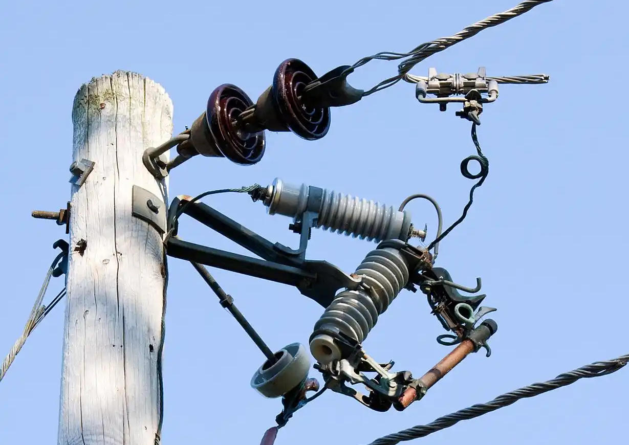
How a Step Up Transformer Works in Real Power Systems
In actual grid architecture, generators often produce power at a lower voltage than the transmission network requires.
A plant may generate at 13.8 kV, then a step up transformer raises this to 132 kV, 220 kV, or 400 kV. This reduces line current and cuts transmission loss dramatically over distance.
In project reviews, this is where transformer design gets demanding. Higher output voltage requires stronger insulation systems, careful bushing design, and strict impulse withstand performance aligned with IEC 60076 and related insulation coordination practices.
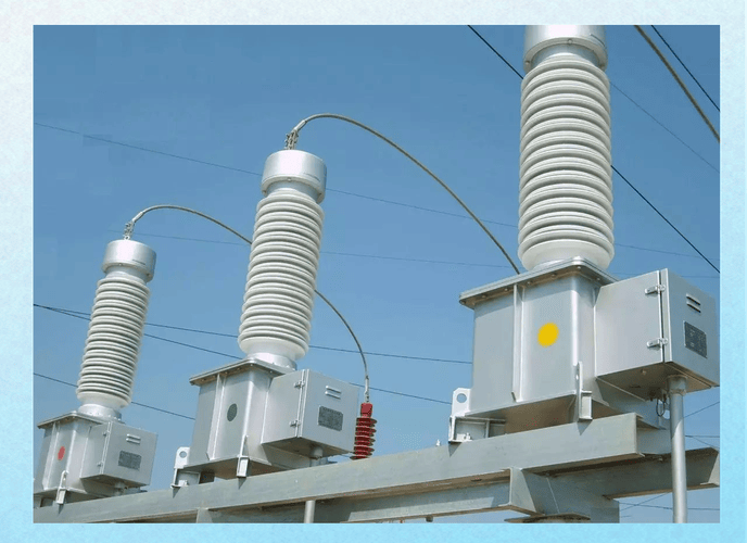
How a Step Down Transformer Works in Real Distribution Networks
After high-voltage power reaches the receiving substation, it must be lowered in stages.
A transmission substation may reduce 220 kV to 33 kV. A local distribution transformer may further reduce 11 kV or 13.8 kV to 400/230 V for commercial and residential use.
This final conversion stage is the one most people interact with every day, even if they never notice the transformer on a pole, pad, or indoor substation room.
Real-World Data and Examples
These are realistic values seen widely in utility systems. Exact voltage classes vary by country and utility.
From my own industry work, the most common customer confusion is around the “middle stages.” They understand a phone charger, and they understand a power plant, but not how medium-voltage distribution bridges the two.
Table: Real-World Voltage Conversion Examples
| Scenario | Input Voltage | Output Voltage | Transformer Type | Purpose |
|---|---|---|---|---|
| Generator to transmission grid | 11 kV to 25 kV | 110 kV to 400 kV+ | Step up | Efficient long-distance transmission |
| Transmission substation | 220 kV | 66 kV or 33 kV | Step down | Regional distribution |
| Primary local distribution | 33 kV | 11 kV | Step down | Urban and industrial feeders |
| Distribution to end users | 11 kV | 400/230 V | Step down | Commercial and residential supply |
| Phone charger adapter | 230 V AC | 5 V to 20 V DC after the conversion stage | Step down | Low-voltage electronics |
| Industrial control circuit | 400 V | 110 V or 24 V | Step down | Safe control power |

Applications of Step Up and Step Down Transformer
The applications of step up and step down transformer systems are very different, even though the principle is the same.
Step Up Transformer Applications
Power generation plants
Transmission grid interconnection
Renewable generation export systems
High-voltage testing equipment
Medical and industrial special equipment
Step Down Transformer Applications
Substations and public utility distribution
Factory incoming power systems
Commercial buildings
Residential supply networks
Electronic adapters and chargers
Control panels, UPS systems, and machinery
Step Down Transformers in Power Distribution Systems
In utility practice, step down transformers are the backbone of the last delivery stage.
A medium-voltage power distribution transformer usually sits between medium-voltage feeders and low-voltage customer networks. This is where voltage becomes practical for motors, lighting, HVAC, data rooms, and homes.
Oil Distribution Transformer in Step Down Applications
An oil distribution transformer is one of the most common solutions for outdoor and utility service.
It reduces voltage safely while using insulating oil for both dielectric strength and heat removal. In my experience, oil units remain the preferred choice where continuous load, outdoor exposure, and long service life matter more than minimal footprint.
Oil-Immersed Distribution Transformer
An oil-immersed distribution transformer has its core and windings submerged in insulating oil.
This oil serves two jobs at once: insulation and cooling. That makes it highly suitable for continuous operation in distribution networks, industrial plants, and compact substations.
Well-designed units commonly follow IEC 60076 or IEEE C57 series requirements for temperature rise, dielectric tests, losses, and routine factory verification.
Hermetically Sealed Distribution Transformer
A hermetically sealed distribution transformer uses a sealed tank so outside air does not contact the oil.
This greatly reduces moisture ingress and oil oxidation. In real maintenance terms, that means more stable insulation performance and lower service attention over time, especially in humid or dusty environments.
Transformer Insulating Oil Cooling System
The transformer insulating oil cooling system removes heat from the core and windings.
Hot oil rises, cooler oil drops, and heat moves toward tank walls or radiators where it dissipates. In larger units, fans or pumps may assist the process.
This cooling method improves thermal performance, insulation reliability, and lifespan. It is one reason oil-filled transformers remain strong choices for demanding duty cycles.
Medium-Voltage Power Distribution Transformer
A medium-voltage power distribution transformer typically receives supply from feeder-level voltages such as 33 kV, 22 kV, 13.8 kV, or 11 kV, then delivers lower voltage for local use.
These units are common in industrial parks, commercial developments, residential communities, and utility pad-mounted or pole-mounted networks.
When I evaluate these transformers for buyers, the practical questions are always the same: ambient temperature, overload profile, installation space, fire safety, efficiency target, and maintenance access.
Advantages and Limitations of Step Up Transformers
Advantages
Reduce transmission current and line losses
Enable economical long-distance power transfer
Support grid integration of generation sources
Limitations
Higher insulation complexity
Greater clearance and protection requirements
More demanding system coordination at high voltage
Advantages and Limitations of Step Down Transformers
Advantages
Deliver safe and usable voltage
Support industrial, commercial, and residential loads
Allow practical voltage control close to end users
Limitations
Larger current on low-voltage side
Copper loss and thermal management become critical
Maintenance needs vary by dry-type or oil-filled design
Common Mistakes When Comparing Step Up and Step Down Transformers
Mistake 1: Thinking a transformer creates extra power. It changes voltage and current, not net power output.
Mistake 2: Ignoring current rise in step down operation. Lower voltage can mean much higher current.
Mistake 3: Looking only at kVA, not insulation class, cooling, or duty cycle.
Mistake 4: Assuming all distribution transformers are the same. Oil-filled, dry-type, and sealed designs serve different environments.
Mistake 5: Overlooking standards. IEEE and IEC compliance is not marketing language; it affects testability, interchangeability, and reliability.

How to Choose the Right Transformer for Your Use Case
Start with the voltage direction.
If your output must be higher than the input, choose step up.
If your output must be lower than the input, choose step down.
Then check these six points:
1. Input voltage and frequency
2. Required output voltage
3. Load in kVA and load profile
4. Installation environment
5. Cooling method
6. Standards and protection level
For utility and industrial buyers, I strongly recommend validating routine test reports, temperature rise limits, short-circuit design strength, and dielectric performance before purchase.
Table: How to Select Between Step Up and Step Down Transformers
| Selection Criteria | Choose Step Up Transformer If | Choose Step Down Transformer If |
|---|---|---|
| Source voltage | The input voltage is lower than the required system voltage | The input voltage is higher than the required load voltage |
| Load requirement | Need higher voltage and lower current transfer | Need a lower voltage for usable equipment supply |
| Industry use | Generation, HV testing, transmission interface | Distribution, buildings, factories, electronics |
| Cooling type | Depends on rating; often advanced oil or forced cooling in larger units | Dry-type or oil-filled, including oil distribution transformer options |
| Installation site | Power plant or grid substation | Substation, pole, pad, plant room, equipment cabinet |
| Standards focus | High insulation coordination and system integration | Safety, efficiency, distribution reliability, maintenance profile |
FAQ
What is the main difference between a step up and step down transformer?
A step up transformer increases voltage from primary to secondary, while a step down transformer decreases voltage from primary to secondary. The first is mainly used for transmission, and the second is mainly used for distribution and end-use supply.
How does the turns ratio differ in step up and step down transformers?
In a step up transformer, the secondary winding has more turns than the primary winding. In a step down transformer, the secondary winding has fewer turns than the primary winding.
Why does current decrease in a step up transformer?
Because transformer power transfer is approximately constant apart from losses, raising voltage means current must decrease. This inverse relationship is a basic result of V × I balance.
Where are step down transformers used in daily life?
They are used in phone chargers, laptop adapters, doorbell transformers, control panels, building power systems, pole-mounted distribution transformers, and residential supply networks.
What are the applications of step up and step down transformer systems?
Step up transformers are used in power plants, renewable export stations, and high-voltage systems. Step down transformers are used in substations, factories, shopping centers, hospitals, homes, and electronic power supplies.
What is an oil-immersed distribution transformer?
An oil-immersed distribution transformer is a transformer whose core and windings are submerged in insulating oil. The oil provides electrical insulation and removes heat during operation.
What is a hermetically sealed distribution transformer?
A hermetically sealed distribution transformer has a fully sealed tank that prevents outside air and moisture from contacting the oil. This helps preserve oil quality and reduces maintenance demand.
How does a transformer insulating oil cooling system work?
The oil absorbs heat from the windings and core, circulates naturally or with assistance, and releases that heat through the tank walls or radiators. This stabilizes temperature and protects insulation life.
What is a medium-voltage power distribution transformer?
A medium-voltage power distribution transformer reduces feeder-level voltage, such as 11 kV or 33 kV, to lower usable voltage for local industrial, commercial, or residential distribution networks.
Conclusion: Step Up vs Step Down Transformer in One Simple View
A step up transformer raises voltage for efficient transmission. A step down transformer lowers voltage for safe and practical use.
Both follow the same electromagnetic principle, but their turns ratio, current behavior, insulation demands, and applications are very different. In real systems, they work together from generation to final consumption.
Compare Transformer Options for Your System
If you are selecting between a step up unit, an oil distribution transformer, an oil-immersed distribution transformer, a hermetically sealed distribution transformer, or a medium-voltage power distribution transformer, the right choice depends on your voltage class, load profile, cooling requirement, and installation environment.
Send us an inquiry today if you want help matching transformer type, rating, and cooling design to your project. For faster technical discussion, you can also contact us directly via WhatsApp for datasheets, drawings, and application support.