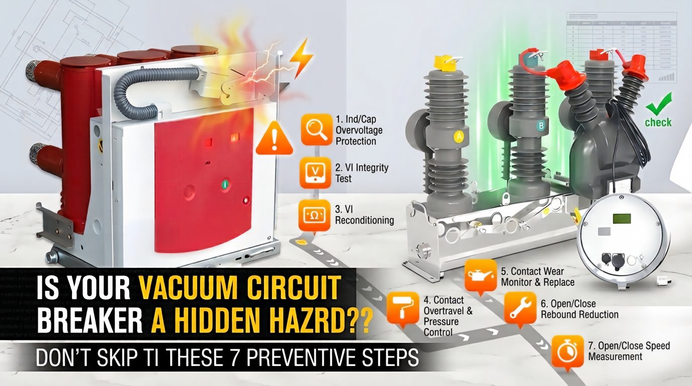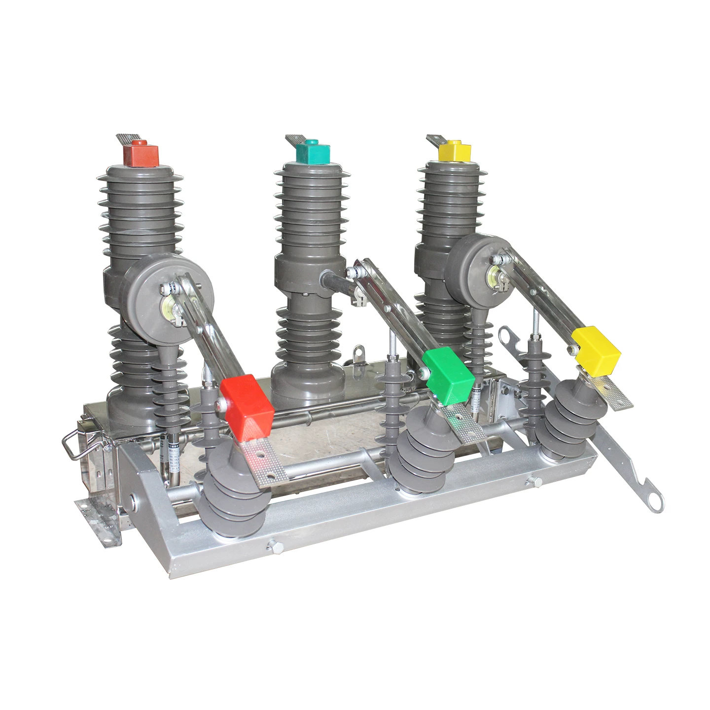
In the field, many engineers, panel builders, and maintenance teams use the term shunt-trip loosely. That is exactly why confusion happens, especially in medium-voltage projects involving a vacuum circuit breaker.
The most common misunderstanding is simple: people assume the shunt-trip coil itself breaks the current. It does not. In real vacuum circuit breaker tripping operation, the shunt-trip only releases the mechanism, while the vacuum interrupter performs the actual current interruption and arc extinction.
This distinction matters in design, troubleshooting, and procurement. It also matters for safety, because a wrong assumption about coil function, voltage, or duty cycle can lead to nuisance trips, failed remote opening, or coil burnout.
This article explains the subject in practical terms, with field-oriented detail, real application examples, and data tables that reflect how these devices are actually used in switchgear.
What Is a Shunt-Trip in a Vacuum Circuit Breaker?
A shunt-trip in a vacuum circuit breaker is an electrically energized trip coil or trip release device that remotely opens the breaker by releasing its stored-energy operating mechanism.
In plain English, it is a remote trip function in circuit breakers. When a short control signal is applied to the coil, the coil moves or actuates a plunger, the trip latch is released, and the breaker opens.
That is the definition that matters in practice.
The shunt-trip is not the current-carrying interrupting element. It is not the arc-quenching chamber. It is not the main protection logic by itself. It is the electrical trigger that tells the breaker mechanism to open.
Inside a VCB, the opening energy is usually stored mechanically in springs. The shunt-trip coil does not need to “force apart” the main contacts by brute force for a long duration. It only has to release the latch so the mechanism can do the work it was designed to do.
This is why a shunt trip coil in vacuum circuit breaker applications is usually designed for momentary energization, not continuous duty.
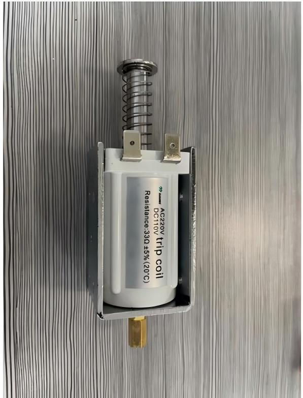
Why Understanding Shunt-Trip Matters in Vacuum Circuit Breaker Protection
If you work with utility panels, industrial switchgear, motor control rooms, transformer feeders, or fire shutdown interfaces, you have probably heard someone say, “The trip coil opened the breaker and extinguished the arc.” That statement is only half true.
The coil helped initiate opening. The actual interruption happened in the vacuum interrupter.
This distinction is important because it affects electrical protection using shunt trip breaker designs. If a user believes the coil is the interrupting element, they may size the control circuit incorrectly, misjudge the failure mode, or overlook the health of the operating mechanism and interrupter.
Here is the practical problem seen on real projects:
Procurement confusion: Buyers ask for a “trip coil” without specifying whether they mean the standard protective opening coil or an optional external shunt-trip function.
Wiring mistakes: Installers connect a continuous signal instead of a pulse output.
Voltage mismatch: A DC 24V control system is connected to a DC 110V coil specification, or vice versa.
Wrong maintenance focus: Teams replace the coil when the actual issue is a sticky latch, discharged mechanism spring, or auxiliary control failure.
In medium-voltage switchgear, remote trip failures are rarely “academic” problems. A failed remote opening command during an emergency stop sequence or fire shutdown event can become a very expensive safety issue.
That is why experienced switchgear engineers always separate three functions clearly:
The command source sends the trip signal.
The shunt-trip coil releases the mechanism.
The vacuum interrupter extinguishes the arc and interrupts the current.
Once those three steps are understood, product selection and troubleshooting become much more accurate.
How a Shunt-Trip Mechanism Works in a Vacuum Circuit Breaker
To understand how a shunt trip mechanism works, it helps to think in sequence rather than in parts.
A vacuum circuit breaker typically stores opening and closing energy mechanically. The shunt-trip is the electrical trigger that unlocks the opening action.
The normal operating sequence is short, fast, and deliberate:
A control pulse energizes the coil.
The coil releases the trip latch.
The mechanism opens the main contacts.
The vacuum interrupter extinguishes the arc during contact separation.
In a properly designed system, this entire chain occurs in a fraction of a second.
Step 1: Control Voltage Energizes the Shunt-Trip Coil
The first step is electrical. A control source applies the rated voltage to the shunt-trip coil for a brief time.
Common control voltages in the field include DC 24V, DC 110V, and AC 220V. These are widely used because they match typical industrial automation, substation, and building auxiliary power architectures.
For example, a PLC output in a factory may issue a 24V DC pulse. A utility protection panel may issue a 110V DC trip signal from the station battery. A commercial building control circuit may use 220V AC because auxiliary AC is already available in the panel.
The key word is pulse. In most cases, the coil is not meant to sit energized for long periods.
Step 2: The Coil Releases the Trip Latch
Once energized, the coil creates a magnetic force. That force moves an armature, plunger, or release element linked to the breaker’s trip latch.
This is where many descriptions go wrong, so let’s be precise: the coil does not break the load current directly. It only unlocks the stored-energy operating mechanism.
Think of it like pressing the release on a spring-loaded mechanical system. The coil is the trigger, not the muscle.
In well-maintained switchgear, the trip release action is quick and repeatable. But in neglected equipment, dust, corrosion, hardened grease, or mechanical wear can increase release force and cause unreliable operation.
That is why mechanical inspection remains essential, even if the coil resistance measures normally.
Step 3: The Vacuum Interrupter Performs the Actual Arc Quenching
After the latch is released, the breaker mechanism opens the main contacts. At that moment, the vacuum circuit breaker tripping operation moves from electrical triggering to power interruption.
As the contacts separate inside the vacuum interrupter, an arc forms briefly. Because the contacts are inside a sealed vacuum bottle, the arc is extinguished rapidly as the current passes through its natural zero and metal vapor condenses.
This is the heart of the interruption process.
So the most accurate statement is this: the shunt-trip initiates opening, but the vacuum interrupter performs the true arc quenching and current interruption.
This distinction is not merely technical wording. It affects testing too.
When diagnosing a failure to open, technicians should check:
Was the correct trip voltage present at the coil?
Did the coil release the latch?
Was the stored-energy mechanism charged and free to move?
Did the breaker poles and vacuum interrupters open correctly?
Skipping any of those steps leads to misdiagnosis.
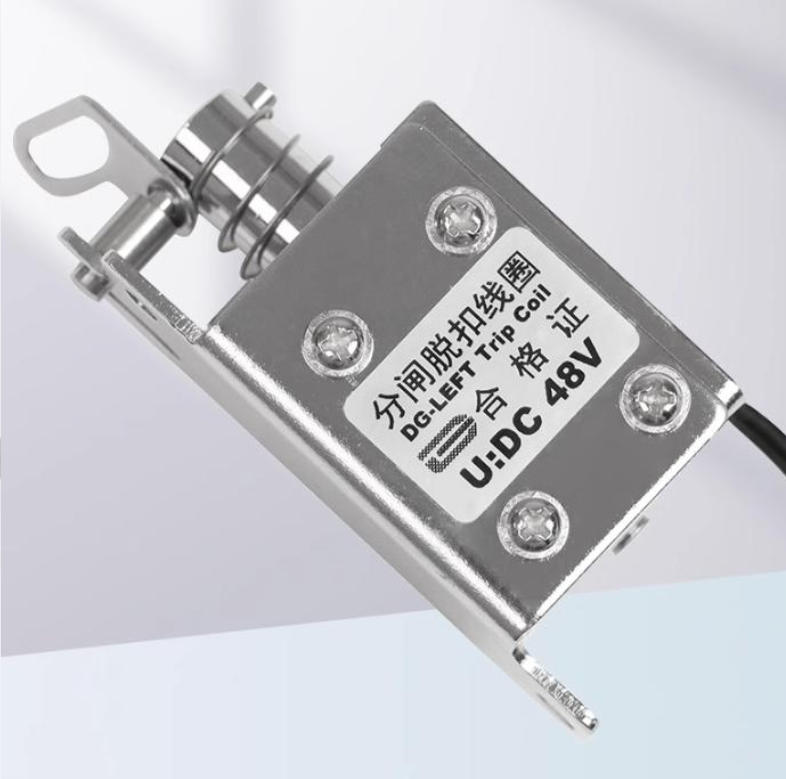
Shunt-Trip vs Standard Protection Trip Coil in Vacuum Circuit Breaker
One of the most common sources of confusion in VCB specification is the difference between a standard trip coil already included in the breaker’s protective opening chain and an optional shunt-trip accessory added for extra remote tripping functions.
The exact terminology varies by manufacturer. That is why engineers should always read the wiring diagram and accessory schedule rather than rely only on a label.
Still, in practical switchgear discussions, the distinction usually looks like this:
Standard Trip Coil in VCB
Many vacuum circuit breakers already include a standard protective opening coil as part of their normal tripping arrangement. This coil works with relays, internal control logic, secondary circuits, and the breaker operating mechanism.
In many designs, when a protection relay detects an overcurrent, short circuit, earth fault, or other abnormal condition, it issues a trip command to this standard opening coil.
That means the breaker can perform its basic protection duty without needing any extra external accessory beyond the intended control scheme.
In field language, this is often just called the “trip coil” or “opening coil.” It is part of the breaker’s basic protective trip chain.
For example, on medium-voltage feeder panels in industrial plants, the protection relay trips the breaker through the standard opening circuit whenever the measured fault parameters exceed the set thresholds.
Optional Shunt-Trip Accessory
An optional shunt-trip accessory usually adds another path for remote opening that is separate from, or supplemental to, the normal protection tripping chain.
This is especially useful where the breaker must open in response to an external system rather than only a protective relay.
Typical examples include:
Fire alarm systems that must disconnect specific feeders
Emergency stop circuits in industrial lines
Access door interlocks in enclosed equipment rooms
Centralized control systems for remote shutdown
Process safety systems that need immediate electrical isolation
In these cases, the optional shunt-trip acts as an additional remote-release interface.
That is why it is important to specify exactly what you need when selecting a vacuum circuit breaker. Asking only for “trip coil” may not be enough. You may need to confirm whether the breaker includes:
a standard protective opening coil,
an additional shunt-trip coil,
both functions,
and how each one is wired and rated.
Manufacturers differ. Some integrate the function more tightly. Others list it as a modular accessory. Reputable suppliers such as Weisho Electric can help clarify this during technical selection, especially when the project includes remote shutdown logic, interlocking, or mixed auxiliary voltages.
Why a Shunt-Trip Coil Must Never Be Energized Continuously
This point deserves blunt language: a shunt-trip coil in a vacuum circuit breaker should generally never be energized continuously.
It is usually designed for short-time duty or momentary duty. In other words, it expects a pulse, not permanent power.
Why is this so important?
Because prolonged energization can overheat the winding, damage insulation, deform internal parts, and eventually burn out the coil. In some cases, the coil may become hot enough to create a secondary reliability issue inside the control compartment.
This is not rare in the field. It usually happens for one of three reasons:
The output signal is configured as maintained instead of pulsed.
A relay contact sticks and leaves voltage on the coil.
The installer assumes the trip coil works like a continuous-duty contactor coil.
That assumption is dangerous.
In practical maintenance work, burned shunt-trip coils often show:
discolored winding varnish,
a strong overheated odor,
insulation resistance deterioration,
or an open-circuit winding on resistance measurement.
Engineers should verify the duty specified by the manufacturer. Many shunt-trip circuits are intended for something like 50 to 200 milliseconds of excitation, sometimes longer depending on design, but still not continuous service.
If a project requires maintained actuation or a hold-open logic, the solution is not to leave the shunt-trip energized. The solution is to redesign the control logic using the correct interlocking method.
In commissioning, one of the simplest but most valuable checks is to measure actual pulse duration with a meter, oscilloscope, or event recorder. That single step can prevent repeat coil failures.
Typical Shunt-Trip Control Voltages and Application Examples
The most common control voltages used for shunt-trip functions in VCB applications are DC 24V, DC 110V, and AC 220V.
Each exists for practical reasons tied to the site’s control architecture.
| CONTROL VOLTAGE | TYPICAL USE CASE | WHY IT IS CHOSEN |
|---|---|---|
| DC 24V | PLC panels, battery-backed controls, industrial automation | Safer low-voltage control and easy integration |
| DC 110V | Substations, protection panels, utility switchgear | Common in legacy and utility DC control systems |
| AC 220V | Building power distribution, commercial control circuits | Convenient where AC auxiliary supply is directly available |
DC 24V is common in factories and process plants. PLCs, remote I/O modules, and automation controllers are often built around 24V DC, so integrating a remote trip function is straightforward.
DC 110V is extremely common in substations and protection rooms. Many utility and industrial power systems use station batteries at 110V DC because the supply remains available even when the normal AC auxiliary source is disturbed.
AC 220V remains practical in many building and commercial systems. Where an AC auxiliary source is already present and approved for the control circuit, it can simplify implementation.
That said, the correct voltage is never a matter of convenience alone. It must match:
the breaker accessory rating,
the actual control supply tolerance,
the command source output capability,
and the project’s safety standard.
A 24V DC PLC output cannot reliably drive a 110V DC trip coil without an interface relay or dedicated power arrangement. Likewise, applying AC 220V to a DC-rated coil will destroy it.
Real-World Example: Remote Trip Function in Circuit Breakers for Fire Safety
Consider a real and very common scenario in a commercial complex or industrial facility: a fire alarm panel must disconnect a feeder supplying non-essential equipment in a hazardous zone.
In this arrangement, the feeder is controlled by a vacuum circuit breaker. The fire alarm system does not interrupt medium-voltage power directly. Instead, it sends a trip command to the VCB’s shunt-trip input.
The sequence typically works like this:
The fire detection system confirms alarm conditions.
The fire alarm control panel closes a relay output or sends a pulse.
The shunt-trip coil receives its rated voltage.
The breaker mechanism releases and opens.
The vacuum interrupter clears the circuit by separating the main contacts and extinguishing the arc.
This kind of interface is valuable because it creates a controlled, engineered shutdown path. The fire alarm logic can isolate selected electrical loads without requiring personnel to approach the switchgear under emergency conditions.
In practice, however, engineering discipline is essential.
The fire alarm output must be compatible with the trip input. The pulse duration must be sufficient. The interposing relay, if used, must be rated correctly. The breaker auxiliary contacts should often provide status feedback so the system can verify that the opening command actually resulted in an open position.
On several retrofit projects, one of the most frequent issues has been using a maintained fire alarm output directly on a momentary-duty trip coil. The first test may appear successful, but repeated operation can overheat the coil.
This is exactly why application-specific coordination matters more than generic catalog reading.
Real-World Data: Typical Operating Characteristics of Shunt-Trip in Vacuum Circuit Breaker Systems
The values below are indicative field ranges, not universal rules for every design. Actual ratings depend on breaker frame, mechanism type, accessory design, and manufacturer data.
Still, these values reflect what engineers commonly see in real shunt trip coil in vacuum circuit breaker applications.
| PARAMETER | TYPICAL RANGE | PRACTICAL MEANING |
|---|---|---|
| Control Pulse Duration | 50-200 ms | Enough to release the mechanism without overheating the coil |
| Trip Command Source | Relay, PLC, fire alarm, E-stop | Supports electrical protection using shunt trip breaker logic |
| Coil Duty | Intermittent/momentary | Not intended for continuous energization |
| Operating Time of VCB | Often 30-60 ms, class dependent | Mechanical opening is fast after latch release |
| Common Auxiliary Supply | DC 24V / DC 110V / AC 220V | Matches site control architecture |
To make the numbers more meaningful, let’s interpret them from a field perspective.
Control pulse duration of 50 to 200 ms is common because the release event itself happens quickly. The coil only needs enough time to actuate reliably.
Operating times in the 30 to 60 ms class are typical for many medium-voltage breakers once the latch has released, though exact timing varies. Faster or slower values can occur depending on design, age, lubrication condition, temperature, and test method.
Command source flexibility is one reason shunt-trip functions are so widely used. A protective relay, PLC, emergency stop, or fire signal can all become valid trip initiators if the interface is engineered correctly.
From a commissioning standpoint, useful real-world checks include:
recording actual control pulse width,
verifying auxiliary supply voltage under load,
timing breaker opening during trip tests,
and confirming that repeated operations do not overheat the coil.
Teams that perform these checks routinely have fewer unexplained remote trip failures later.
Common Mistakes When Using Shunt-Trip With Vacuum Circuit Breaker
Most shunt-trip problems are not caused by exotic electrical theory. They are caused by very ordinary mistakes.
Below are the most common ones seen in design reviews, installations, and service calls.
Continuous energization of the coil
Using a maintained signal instead of a pulse is one of the fastest ways to damage a momentary-duty coil.Wrong control voltage selection
Specifying DC 24V when the site uses DC 110V, or ordering AC 220V because it is “available,” can create immediate incompatibility.Assuming the coil performs arc interruption
This leads to poor troubleshooting. The coil releases the mechanism; the vacuum interrupter does the interrupting.Ignoring manufacturer wiring logic
Some breakers require specific auxiliary interlocks, anti-pumping logic, or release circuits. Guesswork is risky.Underrated command outputs
A PLC transistor output may not have enough capacity to drive the trip coil directly.No feedback verification
Sending a remote trip command without checking breaker position feedback leaves operators blind.Poor maintenance of the mechanical release system
A healthy coil cannot compensate for a sticky latch or neglected mechanism.
One practical lesson from field service is worth emphasizing: if a breaker fails to remote-trip intermittently, do not assume the coil is defective first.
Check the voltage at the coil during the command. Check the pulse duration. Check the latch mechanism. Check the spring charge condition. Check the auxiliary wiring. Intermittent problems often turn out to be control-side issues, not defective accessories.
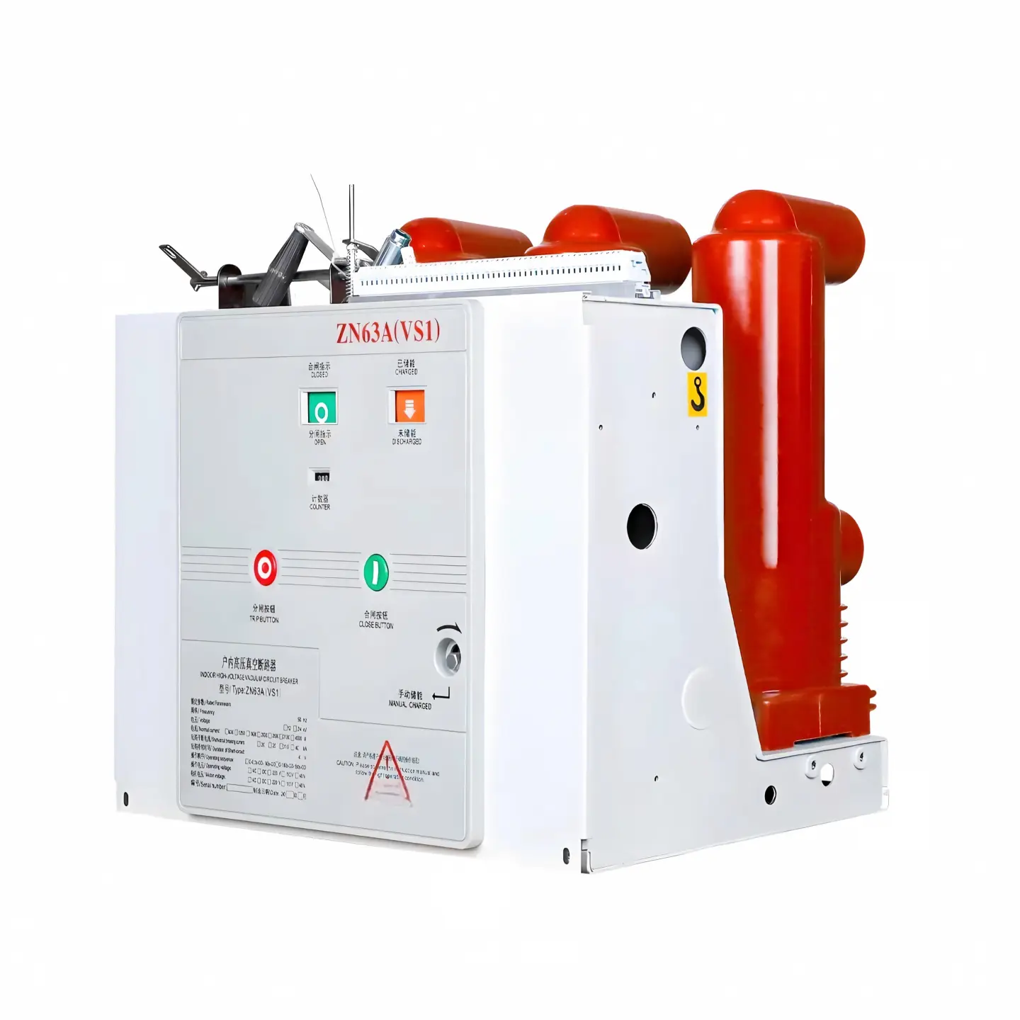
How to Select the Right Shunt-Trip Coil for a Vacuum Circuit Breaker
Selecting the correct shunt-trip arrangement is not difficult, but it requires discipline. A reliable specification should always include more than just the words “with shunt trip.”
Use the following checklist.
Confirm breaker model compatibility
Not every accessory fits every breaker frame or operating mechanism. Match the exact VCB model and revision.Confirm rated control voltage
Choose DC 24V, DC 110V, or AC 220V only after checking the actual site auxiliary supply and tolerance.Verify duty type
Make sure the accessory is intended for momentary operation, and design the control circuit accordingly.Review command source capability
Protection relay contacts, PLC outputs, fire alarm relays, and E-stop circuits all have different electrical limits.Define the control logic clearly
Will the trip come from relay protection, remote SCADA command, fire alarm, door interlock, or all of them?Check environmental conditions
Temperature, humidity, dust, and vibration affect long-term reliability.Confirm standards and project approvals
Especially in utilities, commercial buildings, and safety shutdown systems, documentation and compliance matter.Require wiring diagrams and test procedures
Accessory selection is incomplete without functional verification.
Where projects involve mixed systems such as utility protection plus building fire interfaces plus industrial automation, technical coordination becomes more important than the accessory itself.
This is where experienced support adds value. A technically grounded supplier like Weisho Electric can help users confirm whether they need the standard protective opening coil only, an additional shunt-trip function, or a fully coordinated remote tripping scheme based on actual field conditions.
Quick Summary: What Shunt-Trip Does in a Vacuum Circuit Breaker
Let’s reduce everything to the essential facts.
A shunt-trip is an electrically energized release device that remotely opens a vacuum circuit breaker.
It works by applying a short control pulse to a coil.
The coil releases the latch of the stored-energy operating mechanism.
The mechanism opens the breaker contacts.
The vacuum interrupter performs the actual arc extinction and current interruption.
The coil is typically short-time duty only and should not remain continuously energized.
Common control voltages are DC 24V, DC 110V, and AC 220V.
Many VCBs already include a standard protection trip coil, while an optional shunt-trip may provide additional remote or interlock-based opening capability.
If you remember only one sentence, remember this: the shunt-trip starts the opening action, but the vacuum interrupter does the real breaking work.
FAQ
What is the difference between a shunt-trip coil and a trip coil in a vacuum circuit breaker?
In many vacuum circuit breakers, a standard trip coil is already part of the normal protection tripping chain driven by relays and internal control logic. A shunt-trip often refers to an added remote-opening coil or function used for external commands such as fire alarm shutdown, emergency stop, or interlock-based tripping. Terminology varies by manufacturer, so the wiring diagram should always be checked.
How does a shunt trip mechanism work in a vacuum circuit breaker?
A control pulse energizes the coil, the coil releases the trip latch, the breaker mechanism opens, and the vacuum interrupter extinguishes the arc during contact separation. That is the practical sequence of how a shunt trip mechanism works in a VCB.
Can a shunt-trip coil in a vacuum circuit breaker stay energized continuously?
No. In most designs it should not remain continuously energized because it is generally intended for short-time or momentary pulse duty only. Continuous energization can overheat and damage the coil.
What control voltages are common for shunt-trip in vacuum circuit breaker systems?
The most common control voltages are DC 24V, DC 110V, and AC 220V. The correct choice depends on the site’s control architecture, the breaker accessory rating, and the command source available.
Does the shunt-trip coil extinguish the arc in a vacuum circuit breaker?
No. The shunt-trip coil only releases the operating mechanism. The actual arc quenching takes place inside the vacuum interrupter when the main contacts separate.
Where is remote trip function in circuit breakers commonly used?
Common applications include fire alarm shutdown, emergency stop circuits, access-door interlocks, centralized control systems, and remote protection commands from relays or automation systems.
Talk to a Vacuum Circuit Breaker Expert
If you are specifying a new project, retrofitting switchgear, or troubleshooting a remote trip problem, do not leave the shunt-trip details to assumption. The correct choice depends on breaker model compatibility, control voltage, pulse duty, protection logic, and site operating conditions.
Our team can help you identify the right vacuum circuit breaker configuration, distinguish between standard protective opening coils and optional shunt-trip functions, and match the proper control voltage for your application.
Contact us now to discuss your VCB shunt-trip requirement, request technical guidance, and get a reliable solution before wiring, testing, or procurement mistakes cost you time and money.