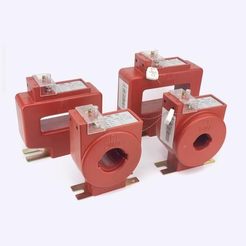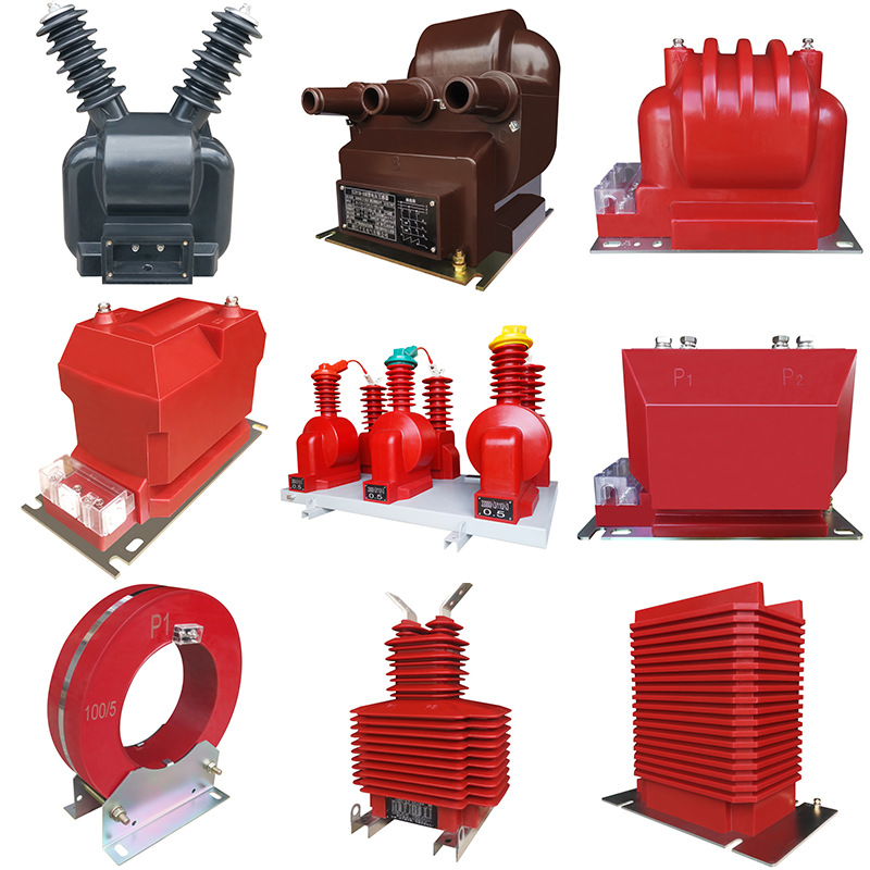
A regular current transformer (CT) and a zero-sequence current transformer (ZCT) both operate by electromagnetic induction, but they do not measure the same quantity.
A regular CT measures the actual current in one phase conductor. A ZCT measures the vector sum of all conductors passing through its core, which is why it is used for earth leakage protection using zero-sequence CT methods and ground-fault detection.
In practical terms, the difference between ZCT and regular CT is simple: a CT tells you how much load current a phase is carrying, while a ZCT tells you whether current is leaking to earth.
Why This Difference Matters in Real Electrical Systems
This is not a small naming difference. In actual switchboards, motor control centers, generator panels, and feeder protection schemes, choosing the wrong transformer can lead to very real failures.
If a designer uses a regular CT where a ZCT is required, the system may miss a ground fault. That means insulation damage can worsen, cable heating can continue, and personnel shock risk can increase before any trip occurs.
If a ZCT is mistakenly expected to provide load current measurement, the result is equally bad. During balanced operation, the ZCT output is near zero, so the operator sees almost nothing even when the feeder is fully loaded.
These mistakes show up in the field more often than many people admit. In low-voltage distribution panels, it is common to find nuisance tripping caused not by a bad relay, but by wrong conductor routing through the zero-sequence core.
In industrial projects, confusion between zero sequence current transformer vs current transformer selection can also affect protection coordination. Overcurrent protection and earth-fault protection are different protection functions, and they need different sensing principles.
Core Principle of a Regular Current Transformer (CT)
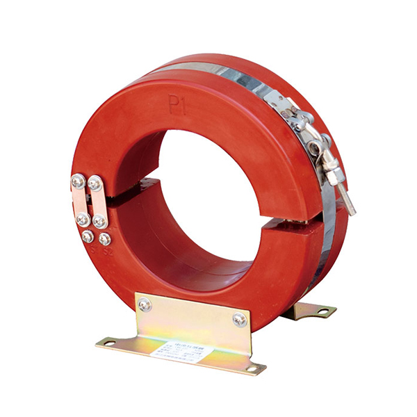
A regular CT is designed to measure the current in one conductor, usually one phase. The primary side is effectively the conductor passing through the CT window or connected to a wound primary.
When current flows in that conductor, it creates magnetic flux in the iron core. The secondary winding then produces a reduced, proportional current according to the CT ratio.
For example, a 100/5 CT means that when 100 A flows in the primary conductor, the secondary current is 5 A at rated conditions. A 200/1 CT would output 1 A at 200 A primary current.
This is why regular CTs are used for:
Ammeters
Energy meters
Power monitoring systems
Overcurrent relays
Short-circuit protection schemes
In a three-phase system, each phase normally needs its own CT. One CT on phase A measures phase A. It does not directly measure phase B or phase C.
Core Principle of a Zero-Sequence Current Transformer (ZCT)
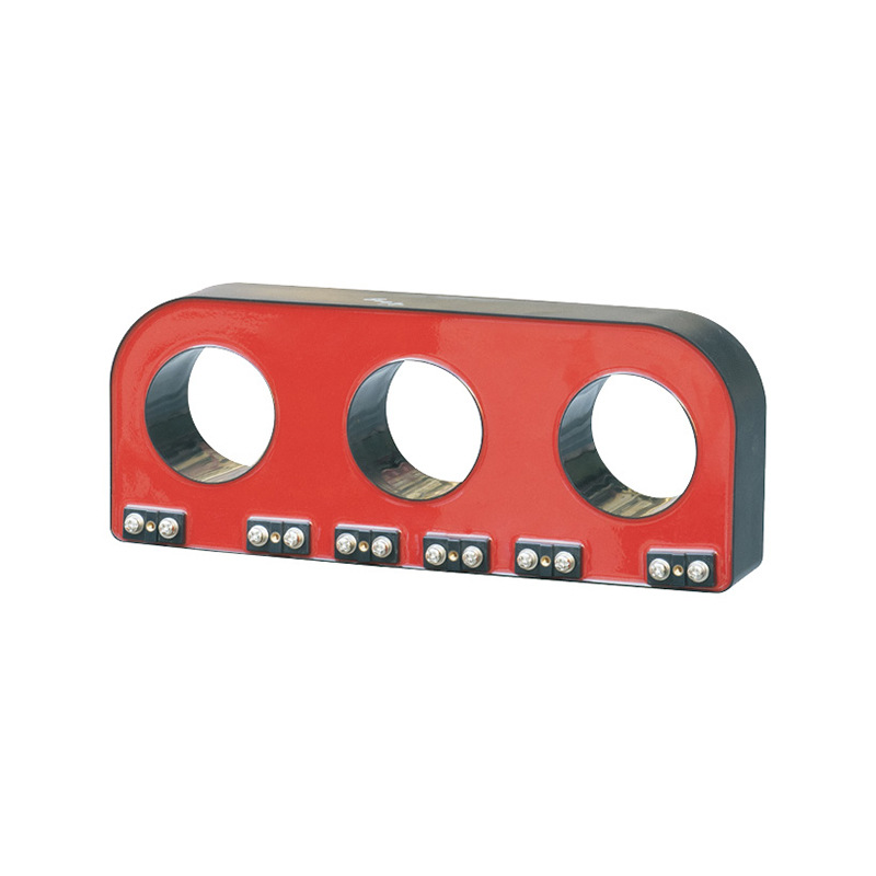
A ZCT uses a different idea. Instead of putting one phase conductor through one core, the installer passes all three phases together through the same ring-shaped core.
In many systems, the neutral conductor must also pass through the same core if it is part of the return path of the protected circuit. That point is critical.
The ZCT does not care about the individual load current of each conductor. It measures the residual current, also called zero-sequence current:
I0 = Ia + Ib + Ic
In four-wire systems, the practical current balance must also consider neutral return. That is why proper routing matters more than many installation teams realize.
This operating method is why a ZCT is also often called a residual current detection transformer or a core balance current transformer.
How a ZCT Works During Normal and Fault Conditions
Under normal balanced three-phase operation, the magnetic effects of the phase currents cancel each other. The net flux in the core is close to zero.
As a result, the ZCT secondary output is also nearly zero. This is normal.
Now consider an insulation failure or a single-line-to-ground fault. Part of the current leaves the intended circuit path and returns through earth or another unintended route.
At that moment, the vector sum of the currents through the ZCT is no longer zero. The core now sees residual flux, and the secondary winding produces an output signal.
That signal is then sent to an earth-fault relay, residual current relay, leakage monitor, or trip unit. If the residual current exceeds the setpoint, the system alarms or trips.
This is the entire reason ZCTs are so effective in earth leakage protection using zero-sequence CT configurations. They are optimized to detect imbalance, not normal load current.
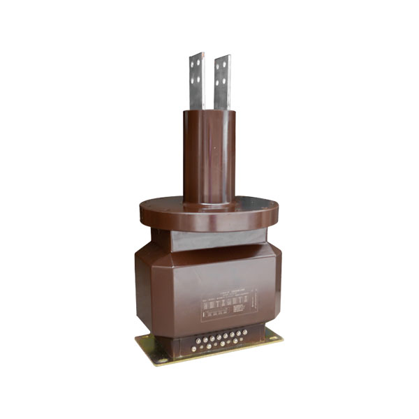
ZCT vs CT: Side-by-Side Comparison Table
| COMPARISON ITEM | REGULAR CURRENT TRANSFORMER (CT) | ZERO-SEQUENCE CURRENT TRANSFORMER (ZCT) |
|---|---|---|
| Measured current | Individual phase current (Ia / Ib / Ic) | Zero-sequence current, or vector sum of phase currents |
| Primary installation | One CT per phase, one conductor through each core | All three phases pass through one common core, often with neutral if required |
| Output in normal operation | Secondary current proportional to load current | Near 0 A when three-phase currents are balanced |
| Main purpose | Metering, ammeters, overload protection, phase-to-phase short-circuit protection | Earth fault detection, leakage protection, single-line-to-ground fault detection |
| Typical paired devices | Ammeters, energy meters, overcurrent relays | Earth fault relays, residual current relays, RCD/GFCI-related systems |
| Core design focus | Accuracy at higher load currents | High permeability and sensitivity to very small leakage signals |
| Fault trigger condition | Current exceeds pickup setting | Residual current is no longer zero due to leakage or ground fault |
Comparison Table: Zero-Sequence CT vs Regular CT
If someone asks for the fastest practical explanation of zero-sequence current transformer vs current transformer, the table above gives the short answer. But in real design work, installation details matter just as much as theory.
A standard CT is built to follow the load current of one phase accurately over a defined operating range. A ZCT is built to notice very small differences between outgoing and returning current.
That sounds subtle. In protection engineering, it is a major difference.
Installation Difference: One Phase Through CT vs All Phases Through ZCT
A regular CT usually has one conductor through one core. If you are measuring a three-phase feeder, you normally use three CTs.
A ZCT is installed around all live conductors together. This is the classic core balance current transformer applications setup.
That means:
Phase A, B, and C must pass through the same core
The neutral must also pass through the core if it is part of the return path
The protective earth conductor must not pass through the core
One of the most common field mistakes is routing the earth conductor through the ZCT window during cramped panel wiring. That creates false cancellation paths and corrupts the residual measurement.
Another common mistake is placing only the three phases through the ZCT in a four-wire load where neutral carries unbalanced return current. In that case, the relay may trip even though there is no real insulation fault.
What Current Does a Regular CT Actually Measure?
A regular CT measures the true line current in a specific conductor. If phase A carries 100 A, the CT on phase A measures that 100 A and scales it to its rated secondary value.
For example:
100/5 CT at 100 A primary gives approximately 5 A secondary
400/5 CT at 200 A primary gives approximately 2.5 A secondary
800/1 CT at 400 A primary gives approximately 0.5 A secondary
This is why regular CTs are the normal choice for energy metering, load studies, demand logging, feeder current display, and overcurrent protection.
If you want to know whether a motor is drawing 72 A or 91 A on one phase, you use a regular CT. A ZCT cannot tell you that in any useful way.
What Current Does a ZCT Actually Measure?
A ZCT measures residual current, not the individual load current of a phase. It looks for the imbalance between outgoing current and returning current.
That makes it ideal for:
Earth leakage protection using zero-sequence CT
Ground fault detection
Insulation monitoring with relay-based alarms
Cable leakage surveillance
Selective feeder earth-fault protection
In many product catalogs, this same device may be labeled as:
Residual current transformer
Residual current detection transformer
Core balance CT
Zero-sequence current transformer
The naming changes by manufacturer and market, but the protection concept is largely the same.
Real-World Example: 100 A Balanced Load vs 300 mA Earth Leakage
Let us use a realistic feeder example because this is where the concept becomes obvious.
Imagine a three-phase feeder supplying a balanced load. Each phase carries 100 A. A regular CT installed on each phase will show approximately 100 A on each phase.
Now put all three phases through one ZCT. Even though the total physical current in the three conductors is large, the vector sum is close to zero during balanced operation, so the ZCT output is near zero.
Now assume insulation damage causes 300 mA to leak from one phase to earth. The phase CT still mostly reads the phase load current, because 100 A dominates that measurement.
But the ZCT now sees that 0.3 A is missing from the normal return balance. That residual current is exactly what it is designed to detect.
In practice, a properly matched relay can easily respond to that leakage level, depending on the relay setting and system design.
Real-World Example Table
| SCENARIO | PHASE A | PHASE B | PHASE C | VECTOR SUM AT ZCT | REGULAR CT OUTPUT | ZCT OUTPUT |
|---|---|---|---|---|---|---|
| Balanced three-phase load | 100 A | 100 A | 100 A | ≈ 0 A | Each CT reads its phase current | Near zero |
| Single-phase earth leakage | 100 A | 100 A | 100 A with 0.3 A leaking to ground | ≠ 0 A | Phase CT still mainly reflects phase load | Leakage signal appears |
| Overload without earth fault | 140 A | 100 A | 100 A | May remain near zero if no leakage path exists | Overloaded phase CT rises proportionally | Usually no earth-fault trip |
| Phase-to-phase short circuit | Very high | Very high | Normal/affected | Often not the main measured value | CT-driven overcurrent protection operates | ZCT may not be primary protection element |
Where Regular CTs Are Used
Regular CTs are everywhere in power systems because current measurement is a basic need in nearly every installation.
Utility metering interfaces
Building main distribution boards
Motor control centers
Switchgear compartments
Feeder protection cubicles
Energy management systems
Generator control panels
Capacitor bank monitoring
They are especially valuable where accurate load measurement is essential. Revenue metering, for example, may require specific accuracy classes and burden limits.
In motor feeders, regular CTs are also used by overload relays and protection relays to detect:
Sustained overload
Locked rotor current
Phase imbalance
Phase-to-phase faults
Short-circuit conditions
A ZCT is not a substitute for these functions. It serves a different layer of protection.
Where Zero-Sequence CTs Are Used
ZCTs are used wherever earth leakage or ground-fault detection matters more than direct load current measurement.
Earth fault relay systems
Residual current detection transformer assemblies
Insulation failure alarm circuits
Cable leakage monitoring
Industrial feeder ground-fault protection
Marine and offshore electrical systems
Mining distribution systems
Motor feeders with sensitive earth-fault protection
Fire-risk circuits requiring leakage supervision
These are classic core balance current transformer applications. The core surrounds all current-carrying conductors, and the relay watches for imbalance.
In practical panel design, many engineers prefer dedicated ZCT solutions over synthesized residual current because installation is simpler and sensitivity is often better.
Manufacturers such as Weisho Electric are often considered when engineers need both standard CT options and purpose-built zero-sequence sensing components for industrial protection panels.
ZCT for Earth Leakage Protection and Ground Fault Detection
The strongest reason to use a ZCT is sensitive residual current detection. In real systems, leakage can begin small and grow over time as insulation degrades.
A ZCT paired with a compatible relay can provide:
Alarm only
Alarm plus time delay
Instantaneous trip
Selective trip coordination
Trend monitoring of insulation deterioration
Typical settings vary widely by application. Personnel protection often uses very low residual thresholds, while industrial feeders may use much higher values to avoid nuisance operation and maintain selectivity.
For example, 30 mA is common for shock protection in certain final circuits. But a large industrial feeder may use 1 A, 5 A, or even higher, depending on charging current, cable length, and system grounding method.
This is why a relay engineer should never copy settings blindly from one panel to another. The protected circuit, cable geometry, leakage background, and grounding arrangement all matter.
Typical Protection Settings and Use Cases Table
| APPLICATION | TYPICAL RESIDUAL SETTING | TYPICAL GOAL |
|---|---|---|
| Personnel shock protection | 30 mA | Fast disconnection to reduce electric shock risk |
| Equipment leakage alarm | 100 mA | Early warning of insulation degradation |
| Fire protection | 300 mA | Detect sustained leakage that may cause heating/fire |
| Industrial feeder earth fault protection | 1 A to 20 A+ | Selective ground fault protection in larger systems |
Example Residual Current Settings Table
These values are typical only. They are not universal settings, and no responsible engineer should treat them as one-size-fits-all rules.
A long cable run, a VFD output circuit, moisture exposure, or a high-capacitance network can all affect background leakage and trip behavior. That is why field measurement and relay coordination studies matter.
Why a ZCT Cannot Replace a Regular CT for Metering
This point is often misunderstood by non-specialists. A ZCT does not provide useful metering of normal three-phase load current because balanced currents cancel out magnetically.
Take a perfectly healthy feeder with 150 A on each phase. A standard CT will show that load clearly.
A ZCT around all three phases will show nearly zero because it is measuring the sum, not the individual current values. For power monitoring, energy logging, or billing, that is useless.
Even when the load is unbalanced, the ZCT output still does not behave like a phase current measurement device. It responds to residual imbalance, not normal phase-by-phase load data.
Why a Regular CT Cannot Fully Replace a ZCT for Leakage Detection
Yes, in some protection schemes, three-phase CTs can be used by a relay to mathematically derive residual current. This is sometimes called zero-sequence filtering or residual summation.
But that is not the same as using a dedicated ZCT. A dedicated residual current detection transformer is typically simpler and more sensitive for small earth leakage detection.
Separate phase CTs also introduce ratio matching issues, saturation differences, wiring complexity, and higher risk of calculation error under fault conditions. For small leakage currents, these effects matter.
So while indirect residual measurement is possible, it is often not the best practical solution when the application specifically demands sensitive earth-fault detection.
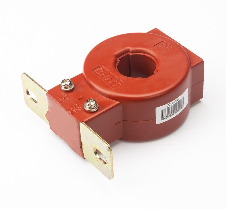
ZCT vs Residual Current Transformer vs Core Balance CT
In everyday engineering language, these terms are often treated as equivalent:
Zero-sequence current transformer
Residual current transformer
Residual current detection transformer
Core balance current transformer
In most practical applications, they refer to the same concept: one magnetic core surrounding all relevant conductors so the device responds to imbalance current.
However, product construction can vary. Some units are optimized for relay input, some for molded-case protection modules, and some for highly sensitive leakage monitoring.
Always check:
Window size
Relay compatibility
Frequency range
Sensitivity range
Insulation class
Mounting form
This is where experienced suppliers can save time. A product line from Weisho Electric, for example, is easier to specify correctly when the application is clearly defined as metering CT, protection CT, or zero-sequence earth-fault sensing.
Zero-Sequence CT vs Zero-Sequence Filter Made from Three CTs
There is an important supplemental point that many articles skip. A zero-sequence filter made from three ordinary phase CTs is not the same thing as a single hardware ZCT.
In the filter approach, three CT secondary signals are combined in a relay or circuit so the residual component is synthesized. This can work well in certain medium-voltage and relay-based systems.
But the hardware is different. A one-piece ZCT physically encloses all conductors in one core, so it senses residual flux directly.
The differences include:
Physical construction
Sensitivity to small leakage currents
Installation complexity
Dependence on matched CT characteristics
Relay processing method
So when someone asks about the difference between ZCT and regular CT, it is also useful to mention that three-CT residual synthesis is a separate approach, not the same device.
Common Selection Factors for Choosing Between CT and ZCT
Good selection starts with the protection objective. Do you need to know the load current, or do you need to know whether current is leaking to ground?
Once that is clear, selection becomes much easier.
Current ratio: Critical for regular CTs used for metering or protection
Window size: Essential for both CT and ZCT based on cable or bus dimensions
Conductor arrangement: Especially important for ZCTs, where all relevant conductors must pass together
Relay compatibility: Secondary characteristics must match relay input requirements
Sensitivity: ZCTs for leakage detection may need to detect mA-level imbalance
Burden: Secondary burden affects accuracy and relay performance
Accuracy class: Key for metering CTs and some protection CTs
Installation space: Panel layout often determines whether ring-type designs are practical
On VFD-fed circuits, harmonic content and high-frequency leakage can complicate selection. On long cable runs, distributed capacitance can raise standing leakage current. On solidly grounded systems, fault current magnitude can be much higher than on resistance-grounded systems.
These are not academic details. They directly affect relay settings and transformer choice.
Common Installation Mistakes That Cause False Readings
Most ZCT problems in the field are not caused by bad cores. They are caused by bad installation practice.
Neutral excluded from the core: In four-wire systems, this often causes false residual current readings
Protective earth routed through the core: This is a classic cause of incorrect operation
Conductors not grouped tightly: Poor geometry can affect measurement stability
Wrong grounding arrangement: Misunderstood return paths can create nuisance trips
Mismatch between relay and transformer: Secondary signal may not suit relay sensitivity
Mixing outgoing and return conductors from different circuits: This guarantees wrong readings
Shield or drain path errors on cable installations: These can create unexpected leakage paths
With regular CTs, common mistakes include open-circuiting the secondary under load, using the wrong ratio, or connecting metering and protection burdens incorrectly.
One practical lesson from field commissioning is simple: if a ZCT trips “for no reason,” start by checking conductor routing before replacing hardware.
Featured Snippet Summary: Difference Between ZCT and Regular CT
A regular current transformer measures the load current in an individual phase conductor for metering and overcurrent protection, while a zero-sequence current transformer measures the sum of all phase currents passing through one core to detect residual current caused by earth leakage or ground faults.
FAQ
What is the main difference between a zero-sequence current transformer and a regular current transformer?
A regular CT measures the current in one phase conductor, while a ZCT measures the residual or zero-sequence current created by imbalance among all conductors passing through its core. In short, a CT is for load current, and a ZCT is for earth-fault or leakage detection.
Does a ZCT measure load current?
Not in a useful metering sense. During normal balanced operation, the currents cancel each other magnetically, so the ZCT output remains near zero even if the feeder carries substantial load current.
Can I use a regular CT for earth leakage protection?
Only indirectly in some relay schemes that sum the outputs of multiple phase CTs. However, a dedicated ZCT is usually more sensitive, simpler to install, and more practical for small leakage detection.
Why does a ZCT output nearly zero during normal operation?
Because balanced three-phase currents create opposing magnetic flux in the core that cancels out. With almost no net flux, the ZCT secondary produces almost no output.
Should the neutral pass through a zero-sequence CT?
If the neutral is part of the protected circuit return path, then yes, it should usually pass through the same ZCT core as the phase conductors. Otherwise, normal return current may appear as false leakage.
What is another name for a ZCT?
It is often called a residual current transformer, residual current detection transformer, or core balance current transformer. The exact name depends on the manufacturer and application.
Can a ZCT detect phase-to-phase short circuits?
That is not its main role. A ZCT primarily detects residual current associated with earth faults, so a pure phase-to-phase fault without ground involvement is usually handled by regular CT-based overcurrent protection instead.
What is the difference between a core balance CT and a zero-sequence CT?
In most practical applications, there is little or no difference. Both terms usually describe the same operating concept: one common core surrounding all active conductors to detect imbalance current.
Conclusion: When to Use CT and When to Use ZCT
If you need to measure phase current, calculate load, feed an ammeter, or drive overcurrent protection, use a regular CT. That is its job, and it does it well.
If you need to detect earth leakage, insulation failure, or ground faults, use a ZCT. That is what it is designed for, and no amount of wishful thinking turns a standard metering CT into a truly sensitive residual current sensor.
So the answer to zero sequence current transformer vs current transformer is not just about terminology. It is about choosing the correct sensing method for the actual fault or measurement objective.
A regular CT tells you how much current is flowing in a conductor. A ZCT tells you whether some of that current is escaping the intended circuit path.
CTA: Choose the Right Transformer for Your Protection Scheme
Do not leave protection performance to assumption. Review your panel design, conductor routing, relay settings, grounding method, and measurement objectives before selecting a CT or ZCT.
If you are specifying a new project, upgrading a feeder, or troubleshooting unexplained earth-fault trips, now is the right time to verify whether your sensing method matches your protection goal.
Talk to a qualified protection engineer or an experienced transformer supplier today, compare your regular CT and ZCT requirements carefully, and choose the right solution before installation errors become downtime, equipment damage, or a safety risk.