I. Introduction: The Shield of Electrical System Safety
Electrical insulators are critically important because they form a "triple barrier," a robust defense mechanism that prevents unintended current flow. This essential function ensures the safety of electrical systems and simultaneously maintains operational efficiency across the entire grid.
By creating a high-resistance isolation zone, insulators act as a buffer between live conductors and the surrounding environment, or between different electrical phases. This action effectively prevents life-threatening electric shocks and mitigates the risk of short circuits and arcing that could easily trigger fires, all while providing necessary physical support for high-voltage lines.
1.1. The Engineer's Perspective: The Value Proposition of Insulators
In power system design, conductors are responsible for the sheer transfer of electrical energy, while insulators are specifically tasked with "restraining" and "guiding" that energy flow safely. Engineers are acutely aware that the overall reliability of any power grid will ultimately be limited by its weakest insulation link.
An insulator is far from a passive material; it must be capable of maintaining stable performance under the triple threat of extreme voltages, unpredictable harsh weather, and immense mechanical loads. This makes it a critical engineering component that delicately balances reliability, economy, and safety within the power system architecture. A deep, comprehensive understanding and the precise application of modern insulation technology are thus fundamental to securing and effectively distributing global energy resources.
1.2. Macro Significance
The advancements in insulator design and application serve as a direct indicator of a nation's technological prowess within its power industry. Every significant material evolution, from the earliest porcelain to subsequent glass insulators and the currently widespread composite types, has driven massive improvements in electrical transmission capacity and overall grid reliability.
Ultimately, grasping the crucial role of the insulator means understanding the core operational logic and the complex safety guarantee mechanisms that underpin the entire modern electrical grid.
Why Do Engineers Call Insulators the "Soul" of the Power Grid?
Key Takeaways
Triple Barrier: The core value of insulators lies in their three main functions: electrical isolation, structural support, and environmental resilience.
Safety Cornerstone: They serve as the final line of defense against fatal electric shocks and prevent short circuits from igniting electrical fires.
Efficiency Assurance: Insulators maintain system efficiency by minimizing leakage current and mitigating power loss from corona discharge.
Critical Metrics: Engineers primarily assess insulators using hard technical parameters such as dielectric strength, creepage distance, and flashover voltage.
Frontier Challenges: Charge accumulation in Ultra-High Voltage Direct Current (UHVDC) systems and severe DC pollution flashovers represent the most complex challenges in contemporary insulation technology.
Development Trends: Composite materials (hydrophobicity) and smart monitoring (partial discharge, infrared) are key directions for enhancing power grid reliability.

II. The Three Engineering Functions and Core Value of Insulators
In the specialized field of electrical engineering, the true importance of an insulator extends far beyond merely "not conducting electricity." It must possess multi-dimensional capabilities, proving its ability to work reliably under the most severe environmental conditions imaginable.
2.1. Function One: Absolute Electrical Isolation and Safety Assurance
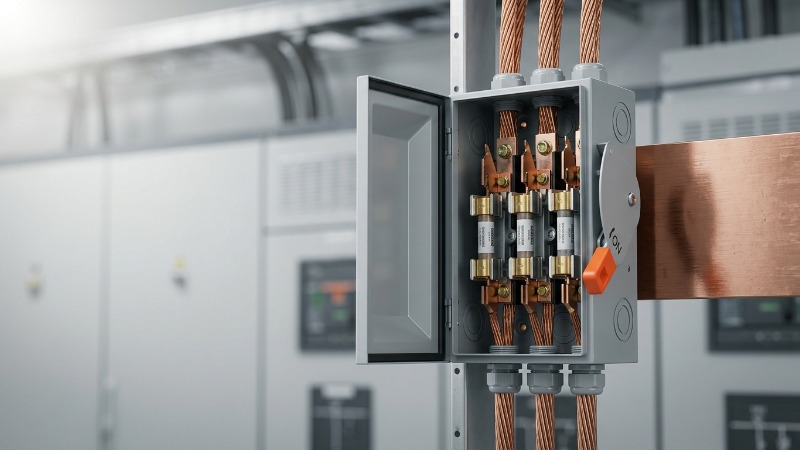
The primary and arguably most critical task of any insulator is to provide absolute and foolproof electrical isolation. Electrons within its material are held tightly bound, which prevents them from forming a mobile flow under the influence of an electric field.
This mechanism completely separates the live, energized conductor from the surrounding environment, the supporting structure, or any human contact. Robust insulation layers specifically ensure that conductors of different phases, or a conductor and the ground, do not experience accidental contact.
A. Protection Mechanism
Insulation failure, if it occurs, instantaneously generates massive short-circuit currents that lead to severe heating, melting, and often a violent arcing event; this scenario is, tragically, the main cause of most electrical fires. The insulator's extremely high Dielectric Strength is the property that allows it to successfully resist the powerful electric field generated by high voltages, thereby preventing catastrophic Insulation Breakdown.
Even in high-voltage transmission settings where air naturally serves as an insulator, excessively high voltage or too close proximity can ionize the air, which creates an arc that acts as an unintended conductive path. Therefore, the physical shape of the insulator (such as its sheds or skirts) is deliberately designed to lengthen the surface path, effectively suppressing any external flashovers.
B. Protection Targets
The most essential function is isolating high-voltage electricity from surfaces accessible to people, directly preventing fatal electric shocks; this is universally recognized as the paramount requirement in all electrical equipment safety codes. Furthermore, robust insulation prevents complex chain reactions of electrical faults throughout the system.
For example, a failure in the internal insulation of a transformer's windings will destroy the entire unit, leading to enormous economic losses and prolonged power outages.
Note: Dielectric Strength is often termed the "compressive capacity" of the insulation material, and it determines the absolute minimum required thickness of the insulating layer needed to safely withstand a specific operating voltage. This critical value is the first and most critical hurdle in any insulation material selection process.
2.2. Function Two: Maintaining Electrical Efficiency and Reliability
Across long-distance and ultra-high-voltage transmission lines, even minor fractions of energy loss can swiftly accumulate into astonishing amounts of wasted power. This means the sheer quality and integrity of the insulator directly impact the fundamental economic efficiency of the entire grid operation.
The constant engineering pursuit of zero loss is an enduring ideal, which necessitates minimizing Leakage Current—a tiny current that flows either across the insulator's surface or subtly through its bulk body. Although individually minuscule, accumulated leakage current over thousands of miles of transmission lines ultimately results in measurable and significant power loss.
Insulators must also effectively suppress Corona Discharge loss, which is the characteristic bluish-purple glow and faint, high-pitched hissing sound caused by the local ionization of air around conductors at extremely high voltages. This phenomenon not only wastes valuable energy but also generates disruptive electromagnetic interference and corrosive ozone.
The optimized design of modern insulators, which often incorporates extremely smooth surfaces and specialized anti-corona rings, aims to homogenize the electric field distribution, thereby effectively suppressing this energy-wasting phenomenon. Insulation failure represents a primary and frequent cause of grid tripping and widespread outages, clearly demonstrating that the reliability of the insulation system directly governs the continuity of power supply. Indeed, in critical power plants and substations, insulation faults carry the high risk of catastrophic equipment damage and potentially widespread power disruption.
Recommended Video: Wet vs Dry Flashover
(This video provides a compelling visual comparison of flashover voltages under dry (air) and wet (surface contamination) conditions, clearly illustrating how environmental factors compromise insulation reliability.)
2.3. Function Three: Mechanical Support in Harsh Environments
Specifically within overhead transmission systems, insulators—here often referred to as Insulator Strings—bear the crucial responsibility of securely suspending the conductors from the rigid towers. In this role, the component functions simultaneously as both an electrical isolation element and a critical mechanical structural component.
Engineers must meticulously conduct mechanical load analysis, carefully accounting for both static loads (which include the dead weight of the conductors and the insulator strings themselves) and heavy dynamic loads. Dynamic forces include the enormous pushing force exerted by strong winds, the severe added weight from ice and snow accretion, and the sudden, instantaneous impact forces that result from conductor vibration or a line break.
Taking the classic Suspension Insulator as an example, these units are typically strung together in series, allowing their total length to be precisely adjusted based on the required voltage level. More importantly, this robust series structure will enable them to withstand immense tensile forces that can easily exceed several dozen tons. The specialized metal fittings and the main insulating body materials (such as high-strength porcelain or tempered glass) must be precisely matched and fabricated to ensure the conductors remain securely attached and structurally intact, regardless of the extreme mechanical stresses imposed by various severe weather conditions.
III. Insulator Hard Metrics: Key Technical Parameters and Selection
For the professional electrical engineer, an insulator is far more complex than just a "non-conductive material"; it is an engineered product defined by a highly comprehensive set of technical specifications. Understanding these core parameters is essential for both evaluating and designing reliable, long-lasting insulation systems.
3.1. Core Electrical Performance Parameters (The Engineer's Language)
These parameters collectively form the scientific basis for accurately judging the quality and specific suitability of any insulating material for a given application.
| Parameter | Definition | Significance | Key Influencing Factors |
| Dielectric Strength | The maximum electric field strength the material can withstand before permanent breakdown (units: kV/mm). | Determines the minimum insulation thickness. It is the fundamental ability to resist internal overvoltages (like switching surges). | Material purity, molecular structure, temperature, and humidity. |
| Creepage Distance | The shortest distance the leakage current flows along the surface of the insulator. | Determines the insulator's resistance to external flashover. Longer creepage distance offers stronger resistance to surface conduction caused by contamination and moisture. | Diameter, number, and shape of the insulator sheds. |
| Flashover Voltage | The minimum voltage that causes a disruptive discharge (breakdown) over the insulator surface or surrounding medium. | The basis for designing safety margins. Must be evaluated for power frequency, lightning impulse, and switching impulse voltages. | Insulator length, surface cleanliness, and atmospheric pressure. |
| Relative Permittivity ($\text{E}_r$) | Measures the material's ability to store electrical energy (capacitance). | Influences the electric field distribution inside and on the surface of the insulation layer. Inappropriate $\text{E}_r$ can lead to localized field concentration and partial discharge. | Material type, fillers, and temperature. |
3.2. Insulator Selection Principles: Coupling Environment and Voltage
Insulators are highly specialized, often customized products whose final selection requires meticulous scientific calculation based on the precise operating environment and the required voltage class.
A. Pollution Level Dictates Creepage Distance
Global grid design standards rigorously categorize operating regions into distinct Pollution Levels (e.g., IEC 60815 standard), acknowledging the vast differences in electrical conductivity between light contamination zones inland versus heavy-contamination zones near coasts or industrial areas. Engineers then determine the necessary Specific Creepage Distance (units: mm/kV, which is the creepage distance divided by the system's highest operating voltage) based directly on this specified level.
For example, in extremely heavy contamination zones, a specific creepage distance of 40 mm/kV or even higher may be technically required. This is essential to prevent contaminants (like salt or industrial dust) from forming a continuous conductive path in wet weather, which ultimately leads to Pollution Flashover.
B. Altitude Correction
As the operating altitude increases, the surrounding air density drops proportionally, which unfortunately causes the insulator's external flashover voltage to decrease. Therefore, in high-altitude regions (such as UHV areas in Western China), insulators must be designed significantly longer or employ special, aggressive high-creepage profiles. This design compensates for the fundamental reduced dielectric strength of the thinner air.
C. Mechanical Strength Matching
An insulator's required mechanical strength is clearly defined by its Specified Mechanical Load (SML). Engineers must ensure the selected insulator's SML significantly exceeds the calculated actual operating loads.
These loads include the most adverse combinations of extreme wind and ice loading, guaranteeing the unit will not fail, fracture, or detach under any extreme operating conditions.
Tip: When undertaking complex insulator selection, the "Specific Creepage Distance" is always a more critical and reliable parameter than simply the total physical length of the insulator. It directly reflects the crucial margin against flashover in a given voltage and pollution environment.

IV. Differentiated Content: Frontier Challenges and Innovations in Insulation Technology
To truly demonstrate the professional engineering depth and the unique perspective of this article, we must pivot to focus on the highest-level challenges currently confronting modern power systems. These include Ultra-High Voltage (UHV) transmission and the emerging smart grid technologies.
4.1. Special Challenges of UHV Direct Current (UHVDC) Insulation
UHVDC systems (ranging from ±800 kV to ±1100 kV) represent the established preferred solution for long-distance, high-capacity power transmission projects. However, they inherently impose far more stringent requirements on their insulators than traditional Alternating Current (AC) systems.
A. DC Charge Accumulation Effect
In standard AC fields, the electric field direction changes 50 or 60 times per second, which renders any internal charge accumulation largely negligible. Conversely, under sustained DC high voltage, the electric field direction remains absolutely constant, causing electric charges to accumulate continuously within and upon the surface of the insulation material.
This persistent Space Charge Effect severely distorts the electric field distribution inside the insulation layer, which can cause localized electric fields to become dangerously high in areas initially designed to be safe. This ultimately triggers Partial Discharge—a primary culprit in accelerating the aging of all insulation systems. Controlling this complex charge accumulation in crucial oil-paper insulation systems, such as in converter transformers and bushings, remains a core technical difficulty in all DC high-voltage designs.
B. The Severity of DC Pollution Flashover
Compared to their AC system counterparts, insulators operating under DC voltage are significantly more prone to disastrous pollution flashover events. The constant, unidirectional DC electric field continually attracts fine, charged contaminant particles to the insulator surface (Electrostatic Adsorption).
Once a wet contamination layer forms, the continuous DC leakage current persistently heats the layer, which ironically creates localized "Dry Bands." While an AC arc crosses zero every half cycle, offering a brief chance for a sustained arc to extinguish itself, a DC arc, once established, is self-sustaining and is far more likely to cause flashover across the entire insulator string. Consequently, CIGRE (International Council on Large Electric Systems) reports that in the same contaminated environment, a DC insulator may realistically require a creepage distance 1 to 10 times greater than its AC counterpart. This fact alone poses unprecedented challenges to the mechanical performance and the overall physical length of UHV insulators.
4.2. The Rise and Technical Advantages of Composite Insulators
Composite insulators—typically composed of a strong glass fiber reinforced plastic rod core, a protective sheath made of high-polymer materials like silicone rubber or EPDM, and specialized metal end fittings—represent a true revolutionary solution. These materials effectively overcome the major limitations of traditional porcelain insulators, particularly in applications exposed to heavy pollution and UHV levels.
A. The Revolution of Hydrophobicity
The single greatest advantage of composite insulators lies in the superb Hydrophobicity (water-repellency) inherent in their silicone rubber sheaths. This property ensures that any water droplets landing on the surface will form isolated, discrete beads instead of spreading into a continuous, conductive film. This action effectively isolates the water from surface contaminants, drastically inhibiting the formation of leakage current and achieving vastly superior Pollution Flashover Resistance when compared to porcelain or glass.
Crucially, silicone rubber exhibits a mechanism called Hydrophobicity Transfer: low-molecular-weight silicone components slowly migrate from the bulk material to the surface, where they successfully encapsulate any contaminants. This allows the insulator to partially self-recover its water repellency even after being exposed to light pollution.
B. Comparison with Porcelain and Glass
| Characteristic | Porcelain/Glass Insulators (Traditional) | Composite Insulators (Modern) | Engineering Application Preference |
| Weight | Heavy (high density) | Lightweight (approx. 1/10th of comparable porcelain) | Lighter tower structures and reduced installation costs. |
| Pollution Resistance | Poor (relies on creepage distance) | Excellent (relies on hydrophobicity) | Preferred choice for severely contaminated regions. |
| Explosion Resistance | Tempered glass can self-shatter; porcelain is brittle. | No shattering risk, high safety factor. | Enhanced safety assurance in transmission corridors. |
| Seismic Resistance | Brittle material, poor seismic performance. | Flexible polymer materials, excellent seismic performance. | Preferred in high-seismic activity zones. |

4.3. Intelligent Monitoring of Insulation Status
The entire modern power grid is currently undergoing a profound transition, moving strategically from the traditional method of "repair after failure" to sophisticated "predictive maintenance." Real-time monitoring of insulation status is, therefore, a core enabling technology that is actively driving this major shift.
A. Online Monitoring Techniques
Partial Discharge (PD) Detection is absolutely vital, as PD represents a faint, telltale discharge signal stemming from internal insulation defects—such as voids, impurities, or interfacial delamination—which occur just before complete breakdown. By using ultrasonic, Ultra-High Frequency (UHF), or Transient Earth Voltage (TEV) sensors to monitor PD signals online, engineers can receive indispensable early warnings about insulation aging and potential internal flaws.
Furthermore, Leakage Current Monitoring involves the real-time measurement of current flowing across the insulator surface, which, when combined with essential environmental data like humidity and temperature, allows for an accurate assessment of surface contamination and the ongoing degradation of hydrophobicity. Lastly, Infrared Thermography involves the routine or online monitoring of the precise temperature distribution across the insulator string. Any detected "Hot Spot" can signal poor internal connections, accelerated aging, or severe corona discharge, serving as a crucial tool for quickly locating urgent faults.
B. Predictive Maintenance
By effectively integrating Internet of Things (IoT) sensor technology, sophisticated big data analytics, and powerful Artificial Intelligence (AI) algorithms, utilities can proactively establish an insulation Health Index Model. This complex model analyzes vast amounts of historical and real-time monitoring data to predict precisely when an insulator is likely to fail.
This capability allows maintenance crews to carry out repairs or replacements at the optimal, proactive time, thereby significantly boosting the grid's operational efficiency and its inherent reliability for all consumers.
【Video Two Placement】
Recommended Video: Hydrophobic vs Hydrophilic Insulator Surface Condition
(This video clearly demonstrates the distinct behavior of water on hydrophilic (e.g., porcelain) versus hydrophobic (e.g., silicone rubber) insulator surfaces, visually explaining why composite insulators possess superior anti-pollution flashover performance.)
V. Conclusion: Outlook and the Engineer's Mission
5.1. Reaffirming the Critical Value of Insulators
Electrical insulators are, unequivocally, the essential bedrock ensuring the "safe, reliable, and efficient" operation of the power grid, with an intrinsic value that far surpasses their simple material cost. Their continuous, ongoing improvement and the persistent investment in insulation technology have been the key factors that have supported stable power transmission from generation sources all the way to the end-users.
This underscores their irreplaceable role in effectively preventing catastrophic equipment failures, minimizing systemic energy loss, and successfully withstanding severe environmental aggression.
5.2. The Engineer's Final View
In the face of the global energy transition, the rapid expansion of UHVDC projects, and the extreme environmental challenges increasingly posed by climate change, the core mission of electrical engineers is clear: to relentlessly innovate in insulation materials and sophisticated diagnostic technologies. Looking ahead, future insulators will evolve strategically toward being lighter, smarter, and more environmentally friendly.
This includes, for instance, the development of fully biodegradable insulating materials or entirely solid-state Gas-Insulated Switchgear (GIS). The scientific evaluation, precise selection, and intelligent maintenance of all insulation systems are absolutely paramount to achieving higher voltage levels, greater transmission distances, and superior reliability across our global electrical transmission networks. Indeed, every power line and every towering transmission structure we see today embodies the profound commitment of insulation engineers to the fundamental safety and efficiency of the entire electric power system.

Frequently Asked Questions
1. Q: How do you differentiate between an Insulator and a Dielectric?
A: Insulator is an engineering term focusing on the practical application of preventing current flow, such as in wire sheathing or tower insulators. Conversely, Dielectric is a physics term referring to a material with specific dielectric properties, typically used to store energy, as in a capacitor's medium, or to withstand an electric field in high-voltage apparatus like transformer oil. All insulators are technically dielectrics, but not all dielectrics are used primarily for insulation.
2. Q: Why is failure immediately visible in glass insulators but not in porcelain ones?
A: Glass insulators typically use tempered glass designed to shatter violently (self-exploding) when internal stresses are released due to damage, leaving only residual fragments that make the faulty unit easy to spot during visual patrol. However, porcelain insulators, being ceramic, can maintain their outward form even after internal cracks or moisture have compromised their insulating ability. Failure in porcelain units often requires electrical tests, such as insulation resistance measurements, to detect a unit that is intact but electrically compromised.
3. Q: Are composite (silicone rubber) insulators less durable than porcelain insulators?
A: Modern composite insulators are generally designed for a life expectancy of at least 30 years, which is fully comparable to traditional porcelain. While early versions sometimes faced issues with interfacial aging and core rod cracking, advancements in material science have vastly improved their UV resistance and hydrophobicity retention. In heavily contaminated areas, their superior anti-pollution flashover capability can mean greater operational reliability compared to porcelain units that require frequent, costly cleaning.
4. Q: What is Partial Discharge (PD), and how does it harm insulation?
A: Partial Discharge is a localized, non-complete breakdown of the insulating medium that occurs inside defects, such as voids, impurities, or regions of high non-uniform electric fields. Although it does not immediately cause full breakdown, the energy it releases—in the form of heat, light, and chemically active particles—continuously erodes the molecular structure of the insulating material, leading to gradual aging and carbonization, which eventually forms a conductive channel and triggers catastrophic insulation failure. PD is considered the most critical indicator of an aging insulation system in high-voltage equipment.
5. Q: What materials are typically used for cable insulation, and how do they differ from overhead line insulators?
A: Cable insulation primarily uses polymer materials like Cross-linked Polyethylene (XLPE) and Ethylene Propylene Rubber (EPR), which are engineered to tightly encase the conductor and withstand the high internal electric fields, focusing mainly on Dielectric Strength and Space Charge control. This contrasts with overhead line insulators (porcelain, glass, composite), which operate externally and rely on the combined effect of the insulator body and surrounding air to provide isolation and mechanical support.
Are you in need of insulation system design, UHVDC insulation selection, or power equipment condition monitoring services for your industrial project?
Our specialized team of electrical engineers is proficient in international standards such as IEC and IEEE, focusing on insulation optimization and fault diagnostics in complex electromagnetic environments. Contact us immediately to receive customized insulation reliability assessments, integration of Partial Discharge (PD) online monitoring systems, or consultation on new composite insulator applications, ensuring the safe and reliable operation of your electrical assets.
[Click Here to Get Professional Technical Consulting and Enhance Grid Reliability]