I. Introduction
Power Transformers and Switchgear are two foundational pillars of any modern electrical power system, yet each performs a fundamentally distinct and critical function. They operate as essential counterparts within the grid infrastructure.
Simply put, the Power Transformer's primary role is to change voltage levels (step-up or step-down), facilitating the economic transmission and distribution of electrical energy across vast distances. This ensures power is moved efficiently.
Conversely, the Switchgear's central mission is to control, protect, and isolate electrical circuits, thereby guaranteeing the system’s safety, stability, and reliable operation at all times. They represent a complementary partnership in the power grid, essential at every stage of the energy supply chain.
From the high-voltage output of a generating station to the low-voltage needs of an end-user, the reliable transfer of energy hinges upon the seamless cooperation between these two components. The Power Transformer functions as the "Energy Parameter Converter," ensuring that electrical energy arrives at its destination with maximum efficiency.
In sharp contrast, the Switchgear acts as the "System Safety Manager," equipped to instantly diagnose and isolate faults, protecting extremely valuable equipment and, most importantly, ensuring personnel safety. For any engineer involved in the design, installation, or maintenance of power systems, a crystal-clear understanding of the essential differences is absolutely paramount.
This comprehensive article will delve into the professional distinctions and collaborative mechanics of these devices across three crucial engineering dimensions: Selection, Operations & Maintenance (O&M), and Safety Protocols. This depth is required to maintain a system that is high-efficiency, reliable, and fundamentally safe.
💡 Recommended Visual Supplement: To gain an intuitive, real-world understanding of Power Transformer and Switchgear structures and maintenance, we strongly recommend watching the following video:
Key Takeaways
Core Function: The Power Transformer is an Energy Conversion device that fundamentally alters voltage parameters; it changes the nature of the energy itself. The Switchgear is a Control, Protection, and Isolation system that actively manages circuit flow and security.
Operating Principle: Transformers rely on Electromagnetic Induction and operate in a static, continuous state. Switchgear relies on Mechanical Actuation and Arc Quenching and involves dynamic operation whenever a circuit needs attention.
Selection Priority: Transformer selection centers on Capacity (MVA) and Short-Circuit Impedance (Z). Switchgear selection focuses critically on Short-Circuit Interrupting Capacity and Insulation Level (BIL).
O&M Focus: Transformer maintenance emphasizes Dissolved Gas Analysis (DGA) and thermal monitoring, following a predictive maintenance model. Switchgear maintenance stresses Mechanical Operational Testing and relay protection verification, utilizing a preventative maintenance approach.
System Security: The Switchgear's breaking capacity must rigorously exceed the maximum short-circuit current that the Power Transformer can generate. This mandates precise Protective Relay Coordination.
II. Fundamental Differences in Core Function and Principle
To accurately differentiate between a Power Transformer and Switchgear, one must first look closely at the distinct engineering purpose behind their existence. This involves understanding the basic physical principles governing their operation.
2.1 The Power Transformer: The Static Converter of Energy Parameters
The Power Transformer is, by definition, a static electrical machine, its name clearly defining its sole purpose: to change (Transform) the voltage. Its invention provided the perfect solution to the fundamental challenge of maintaining efficiency during long-distance transmission of electrical power.
Faraday’s Law of Electromagnetic Induction exclusively governs the operation of a Power Transformer, a principle dictating that an alternating current passing through the primary winding creates a corresponding alternating magnetic flux. This resulting magnetic flux then induces an electromotive force (EMF) in the secondary winding.
This action successfully transfers and converts electrical energy from one specified voltage level to another. The core engineering objectives for its placement in the grid are twofold and mutually dependent.
Efficiency Optimization (Step-Up): Due to the power loss formula—where loss equals current squared multiplied by resistance—higher voltages equate to lower current for a fixed power level. Transformers are thus used at the power plant output to step up voltage, enabling long-distance, economically efficient, and low-loss transmission.
Load Matching (Step-Down): Closer to the end-user, the high or medium voltage must be stepped down to lower, usable voltage levels. These levels precisely match the operational requirements of various consuming equipment and appliances.
Note: A Power Transformer is inherently a Passive device; its operation involves only changing the parameters of the electrical energy, without itself consuming or actively interrupting the flow of power, discounting its internal operational losses. Its normal operational state is static and continuous, requiring no mechanical movement for energy conversion.
2.2 The Switchgear: The Dynamic Guardian of Circuit Flow
The Switchgear represents a dynamic and integrated assembly of electrical systems, effectively acting as the entire power system’s "brain" and "safety valve".
It is an assembly of electrical devices purposefully housed within a protective metal enclosure, specifically engineered to control, protect, and isolate electrical circuits and systems. Its core components include crucial dynamic elements like circuit breakers, disconnect switches, protective relays, and robust busbars.
Its critical operational objectives are also twofold:
Safety Assurance: The paramount function is to quickly and selectively interrupt the flow of electricity during a system fault, such as a short circuit or ground fault. This action prevents catastrophic damage to high-value assets like transformers and cables, and crucially, safeguards personnel.
Circuit Management: Switchgear allows authorized operators to manually or remotely control specific circuits, managing power distribution and re-routing energy flow. This is done according to changing load demands or scheduled maintenance requirements.
Tip: The Switchgear functions as an Active control system; it manages current flow dynamically through mechanical actuation and highly specialized equipment. Its performance is critically judged by two metrics: its speed of interruption and its capacity for arc quenching during a fault event.
III. Key Engineering Differences: A Parameter-Based Comparison
A professional comparison, utilizing standard engineering parameters, is the most effective way to highlight the essential functional disparity between these two critical power components.
| Comparison Dimension | Power Transformer | Switchgear |
| Core Function | Voltage/Current/Impedance Conversion | Power Control, Protection, and Isolation |
| Energy State | Continuous Conversion (Static Device) | Dynamic Switching (Mechanical Operation) |
| Operating Principle | Electromagnetic Induction | Arc Quenching, Mechanical Operation, & Relay Protection |
| Critical Selection Specs | Capacity (kVA/MVA), Voltage Ratio, Short-Circuit Impedance (Z) | Rated Voltage/Current, Short-Circuit Interrupting Capacity, Insulation Level (BIL) |
| Key Internal Components | Windings, Core, Tank/Insulation Medium (Oil/Resin) | Circuit Breakers, Disconnects, Busbars, Protective Relays, CTs/PTs |
| Design Lifespan | Long, due to the static nature (typically 40–60 years) | Medium, limited by mechanical operations (typically 20–40 years, requires cyclic maintenance) |
IV. Critical Technical Parameters and Engineering Selection
The selection of Power Transformers and Switchgear requires distinct sets of engineering considerations; ignoring the specialized metrics for either component will inevitably lead to system instability or outright catastrophic failure.
4.1 Insulating Medium: Balancing Environmental Factors and Safety
The choice of insulating medium is a foundational decision in the system design process, involving critical trade-offs between cost, heat management, and installation environment safety requirements.
Power Transformer Insulation Choices:
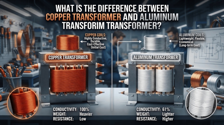
The traditional Oil-Immersed Power Transformer offers lower initial cost and superior heat dissipation. However, it mandates stringent fire suppression and containment measures due to the flammability of mineral oil.
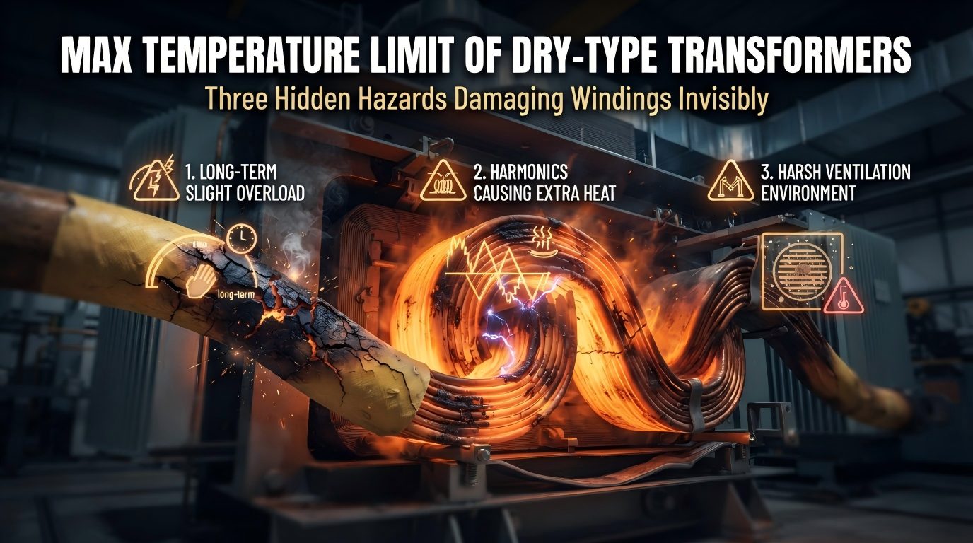
Conversely, the Dry-Type Power Transformer provides superior fire safety, making it ideal for indoor installations or high-rise buildings. Though safer, it may face limitations in cost and high-voltage endurance. Ultimately, the choice must be dictated by a rigorous assessment of the installation location’s specific fire classification and safety regulations.
Switchgear Insulation Choices:
Switchgear insulation decisions often involve a trade-off between compact size and environmental impact, particularly concerning the use of arc-quenching gases. While SF6 (Sulfur Hexafluoride) offers superior insulating performance, its extremely high global warming potential has led to a major industry push toward replacements.
Today, Vacuum Technology and Eco-Friendly Gases are increasingly being adopted to reduce both footprint and environmental liability. These options are necessary to meet modern environmental standards.
4.2 System Coordination: Impedance and Breaking Capacity
This element represents the single most crucial point of integration and safety coordination between the two devices. The entire safety integrity of the power system hinges on this relationship.
Short-Circuit Impedance (Z) of the Power Transformer:
The percent impedance (Z) of the Power Transformer is an intrinsic property reflecting its internal reactance. This value directly determines the maximum short-circuit current that the system can deliver to the downstream circuit. The Transformer's impedance effectively acts as an inherent current limiter during fault conditions.
Interrupting Capacity of the Switchgear:
The short-circuit interrupting capacity of the Switchgear's circuit breakers must be equal to or demonstrably greater than the maximum short-circuit current calculated to be supplied by the Power Transformer. Engineering design teams must perform rigorous short-circuit calculations to confirm this vital safety match.
Note: If the Switchgear's interrupting capacity is mistakenly rated lower than the maximum short-circuit current the Power Transformer can deliver, the circuit breaker will fail to safely clear the fault. This failure often results in a catastrophic, explosive failure.
4.3 Load Adaptability and Specialized Parameters
Modern electrical systems introduce complexities that necessitate specialized considerations beyond simple voltage and current ratings.
For systems dealing with non-linear loads, such as large data centers, server farms, or Variable Frequency Drives (VFDs), the Power Transformer selection must account for a specific K-Factor. This critical factor is necessary to prevent excessive overheating and premature aging caused by harmonic currents generated by those non-linear loads.
In applications demanding frequent switching, such as certain industrial processes, the Switchgear selection places a heavier emphasis on the circuit breaker's mechanical lifespan and operation cycles (MOPs). These mechanical factors are often more critical than solely its electrical protection ratings.
V. Differentiated Safety Protocols and O&M Strategies
The distinct operational nature of each device leads to fundamentally different primary hazards and, consequently, divergent maintenance and safety philosophies.
5.1 Primary Hazards and Protection Focus
The inherent risks associated with static conversion versus dynamic switching demand entirely separate protective measures and system designs.
Power Transformer Hazards: Fire and Explosion
Primary Hazard Sources: These generally stem from overheating caused by the aging of insulating oil, insulation breakdown, or internal winding faults.
Protection Focus: Protection strategies heavily rely on early warning indicators like Dissolved Gas Analysis (DGA), continuous temperature monitoring, and the use of mechanical pressure relief devices.
Switchgear Hazards: Arc Flash Incident
Primary Hazard Sources: This extremely violent event is caused by a phase-to-phase or phase-to-ground short circuit within the enclosure. It instantly releases an immense amount of thermal energy and a powerful pressure wave.
Protection Focus: Safety is secured through the use of arc-resistant internal designs, the installation of highly sensitive Arc-Flash Detection Systems, and strict enforcement of the Lockout/Tagout (LOTO) procedure, requiring proper Personal Protective Equipment (PPE) for all personnel.
5.2 O&M Focus: From Predictive Monitoring to Preventive Action
Maintenance strategies are clearly split between highly sophisticated predictive analytics for the Transformer and routine mechanical assurance for the Switchgear.
Power Transformer O&M (Primarily Predictive):
The core of Transformer maintenance revolves around continuous insulation condition monitoring, leveraging chemical analysis to predict imminent failure. The most critical procedures include DGA Analysis (the most effective predictive tool), infrared thermal imaging, and dielectric strength testing of the insulating oil.
Switchgear O&M (Primarily Preventive):
Switchgear maintenance focuses on the reliability of the mechanical operating mechanisms and the integrity of the contact surfaces. Key preventative tasks include Contact Resistance Measurement (to preempt overheating), Breaker Timing Tests (to ensure required speed of operation), and periodic calibration/verification of the protective relay settings.

Tip: In Power Transformer DGA results, the presence and concentration of Acetylene ($C_2H_2$) is considered the gold-standard indicator for diagnosing high-energy electrical arcing faults deep within the unit.
5.3 Sustainability and Environmental Responsibility
Modern grid management increasingly demands environmental consciousness, leading to differentiated sustainability efforts for each device.
For Power Transformers, the industry is heavily promoting the adoption of High-Efficiency Amorphous Metal Core Transformers to significantly lower no-load losses, thereby conserving energy. There is also a major push toward using Synthetic Ester Liquids as environmentally friendly substitutes for traditional mineral insulating oil.
For Switchgear, the focus is squarely on the phase-out of SF6-insulated switching equipment, instead encouraging the widespread use of Vacuum Interruption Technology and newer, SF6-Free Eco-Friendly Gas Insulated Switchgear. This critical shift is necessary to meet global environmental commitments.
VI. Synergy and System Integration: Building a Reliable Power Chain
Although functionally separate, the effective performance of the overall power system depends entirely on the robust, coordinated integration of Power Transformers and Switchgear.
6.1 Protective Coordination and Fault Selectivity
This is the cornerstone of all electrical protection design, where safety and reliability are intrinsically linked. Engineers must meticulously design and verify the operating times and settings of the protective relays on all Switchgear circuit breakers on both the high and low voltage sides of the Transformer.
This careful configuration must establish a clear time-current curve hierarchy, ensuring that in the event of any fault, only the circuit breaker nearest to the actual fault location trips. This action thereby achieves perfect Fault Selectivity.
6.2 Advanced Integration: The Unit Substation
The Unit Substation represents a highly efficient and integrated design that physically combines the Power Transformer, medium-voltage Switchgear, and low-voltage Switchgear into a single, compact metal enclosure. This integrated construction drastically simplifies field installation.
It simultaneously saves floor space and significantly enhances the overall safety and reliability of the entire system by reducing external connections.
6.3 Advanced Linkage with UPS Systems
In mission-critical environments, such as data centers and hospitals, the Switchgear must work in precise coordination with the Uninterruptible Power Supply (UPS) system to maintain uptime. The Switchgear's protective relay action time must be carefully coordinated with the UPS's "ride-through time" and battery capacity.
This synchronization allows the UPS to use its static switch to transfer the load to backup power in the millisecond range. This action successfully preempts any unnecessary protective trips by the Switchgear during momentary grid disturbances.

Note: The rigorous design of Protective Coordination is the fundamental determinant of a power system's Fault Selectivity, and is often cited as the crucial differentiator between a fully qualified engineer and a mere technician.
VII. Conclusion
In summary, the roles played by Power Transformers and Switchgear within the electrical power system are fundamentally distinct and mutually essential. The Power Transformer functions as the "Energy Parameter Optimizer," specializing in the efficient conversion of electrical energy across voltage levels.
Conversely, the Switchgear is the indispensable "System Safety Guardian," focusing entirely on the control, protection, and security of that energy flow.
From an electrical engineer’s perspective, professional competency requires mastering not only their theoretical operating principles but also their critical engineering parameters (like short-circuit impedance (Z) and interrupting capacity). It is equally vital to understand the key selection criteria (such as insulation medium and environmental impact) and specialized O&M strategies (like DGA analysis and Arc Flash protection).
It is only by performing stringent protective coordination and detailed cascade calculations during the initial design phase that the system’s efficiency, stability, and long-term safety can be fundamentally guaranteed. For any organization, the professional management and rigorous maintenance of these two core devices are absolutely critical for securing long-term operational continuity and minimizing costly, unscheduled downtime.
Frequently Asked Questions (FAQ) & Professional Service Conversion
Is it possible to omit either the Power Transformer or the Switchgear, especially since they are often physically located together in a substation?
Absolutely not; they are functionally complementary and inseparable.
The Power Transformer effectively changes the voltage but cannot provide crucial circuit protection or fault isolation, while the Switchgear successfully protects and controls the circuit but fundamentally cannot change the voltage level. Therefore, they must operate in tandem, with the Power Transformer and its associated Switchgear (on both high and low voltage sides) forming a complete and essential functional unit within any electrical room or substation.
What is the specific relationship between the Switchgear's Interrupting Capacity and the Power Transformer’s Rating (MVA)?
The relationship is highly critical and direct.
The Power Transformer's rating and its short-circuit impedance (Z) together determine the maximum short-circuit current that can possibly occur on the secondary side. The Switchgear's circuit breaker interrupting capacity must be safely capable of clearing this maximum calculated fault current. Engineers must always begin by calculating the maximum fault current from the Transformer's parameters before they select the appropriately rated Switchgear.
My facility uses an oil-immersed Power Transformer, and I am concerned about fire risk; what is the most professional O&M step to enhance safety?
Your concern is valid, as oil-immersed units do carry inherent fire risks.
The most advanced and professional measure is to perform routine Dissolved Gas Analysis (DGA) testing and comprehensive oil inspections. DGA meticulously analyzes trace gases within the oil to detect the earliest signs of internal faults—such as partial discharge, localized overheating, or arcing—months before a catastrophic failure occurs.
What is an Arc Flash, and why is it so closely associated with Switchgear?
An Arc Flash is a massive, high-intensity discharge of light and heat—reaching tens of thousands of degrees Celsius—that instantly results from a short circuit inside Switchgear or other electrical equipment.
It represents the single greatest physical safety hazard faced by Switchgear maintenance personnel, requiring specialized Arc Flash Analysis, the use of rated PPE, and the installation of high-speed arc detection and protection systems.
Our site is a data center with extremely high reliability requirements; besides Power Transformers and Switchgear, what other equipment is absolutely essential?
You must configure a robust Uninterruptible Power Supply (UPS) system and an adequately sized backup generator set.
The Power Transformer steps the voltage down, the Switchgear provides protection, and the UPS ensures instantaneous, high-quality power during even momentary grid fluctuations, guaranteeing continuous operation of critical IT loads.
Given the environmental harm caused by SF6 gas, what is the clear industry trend for Switchgear?
SF6 is recognized globally as a potent greenhouse gas, posing a significant environmental challenge to the power industry.
The decisive industry trend involves the systematic phase-out of SF6-insulated switchgear, transitioning instead to vacuum interrupter technology and newer eco-friendly gas-insulated solutions (like dry air or gas mixtures) to support a much greener power infrastructure.
Why is the Detection of Acetylene (C2H2) in Power Transformer DGA Results Critical?
Acetylene gas (C2H2) is a product of electrical decomposition that is generated only at extremely high temperatures, specifically above 700°C.
Therefore, the presence of acetylene in the insulating oil is considered near-conclusive evidence of a high-energy electrical arcing fault or a severe hot-spot thermal failure inside the power transformer. This often necessitates an immediate shutdown for internal inspection and repairs.
Professional Consulting & Service Call to Action
The safety and efficiency of your electrical infrastructure fundamentally begin with professional engineering design and diligent, proactive maintenance and diagnostics. Whether you are currently facing the complex design challenge of short-circuit calculation and protective relay coordination for a new substation, or you require an authoritative assessment of your existing assets through Power Transformer DGA analysis and Switchgear Arc Flash evaluation, our team of professional electrical engineers is ready to deliver reliable, compliance-driven solutions.
Contact us today to receive a customized power system optimization proposal that will ensure your operations are efficient, safe, fully compliant, and aligned with the latest industry sustainability standards.