Empirical evidence demonstrates that a single ground fault event of sub-millisecond duration possesses sufficient energy to inflict catastrophic damage on precision CNC equipment valued in excess of $200,000, irrecoverably compromise extended datasets accumulated over months of laboratory investigation, or — within clinical environments — present a direct threat to patient safety. The protective infrastructure capable of mitigating all three failure modes represents a capital expenditure substantially below the cost burden associated with one week of unplanned operational downtime across most industrial sectors.
The 240V isolation transformer sits at the intersection of electrical safety, power conditioning, and operational continuity. For decision-makers responsible for facilities where equipment uptime and personnel safety are non-negotiable, understanding how to specify, justify, and deploy these devices is a core competency — not a nice-to-have.
This guide equips you with the technical knowledge, cost-benefit data, and selection criteria needed to specify the right isolation transformer for your facility, whether you operate a hospital, a manufacturing plant, a data center, or a research laboratory.
Where 240V Isolation Transformers Are Used and How to Choose the Right One
The core use cases span multiple sectors: healthcare facilities protecting patient-contact equipment from leakage currents, industrial plants shielding PLCs and CNC machines from ground faults, data centers isolating server racks for fault containment, and laboratories requiring clean power for precision instruments.
Choosing the right unit comes down to four factors — load size (kVA), compliance requirements, shielding grade, and installation environment. The following decision framework simplifies the specification process:
1. Step 1: Identify your application sector and the regulatory standard it falls under (IEC 60601, NFPA 99, TIA-942, IEC 61010)
2. Step 2: Calculate total apparent power (kVA) of connected loads plus 20–25% headroom for inrush and future expansion
3. Step 3: Determine shielding level — single versus double Faraday shield — based on the noise sensitivity of your equipment
4. Step 4: Match enclosure rating and insulation class to your physical environment (indoor clean, industrial harsh, outdoor exposed)
Market demand continues to accelerate, driven by the proliferation of sensitive electronics, rapid data center expansion, and increasingly stringent safety regulations across all major economies. Organizations that delay specification often find themselves retrofitting under pressure — at significantly higher cost.
How a 240V Isolation Transformer Works
Core Operating Principle — Galvanic Isolation Explained
An isolation transformer uses two physically separate windings — primary and secondary — with no direct electrical connection between them. Energy transfers exclusively through magnetic coupling via a shared core, creating a complete break in the galvanic path between input and output circuits.
This separation blocks DC faults, voltage transients, and common-mode noise from propagating between circuits. Any fault on the primary side cannot establish a return path through the secondary's connected equipment or personnel.
The critical distinction from a standard step-down transformer is purpose: a step-down transformer changes voltage level (e.g., 415V to 240V), while an isolation transformer maintains the same voltage on both sides (240V to 240V). The value lies not in voltage conversion but in breaking the fault path.
Key Electrical Characteristics at 240V
True isolation applications use a 1:1 turns ratio, delivering the same 240V output as input. The primary and secondary windings are wound on the same core but separated by reinforced insulation rated for the full working voltage plus safety margins.
A Faraday shield — an electrostatic screen placed between primary and secondary windings — intercepts capacitively coupled noise. This grounded copper or aluminum foil layer is the key differentiator in noise filtering performance between basic isolation and premium units.
Leakage current specifications determine suitability for safety-critical applications. Medical-grade units achieve sub-50µA earth leakage, while standard industrial units may allow up to 300µA. In patient-contact scenarios, every microamp matters.
Power Conditioning Benefits Beyond Isolation
Beyond galvanic separation, quality isolation transformers deliver measurable power conditioning. Common-mode noise rejection typically reaches 120–140 dB, eliminating interference that disrupts sensitive electronics and measurement instruments.
Transient voltage spikes — from lightning, switching events, or motor starts elsewhere on the distribution system — are attenuated before reaching protected loads. The transformer's inductance acts as a natural low-pass filter for high-frequency disturbances.
In environments with nonlinear loads (variable frequency drives, switch-mode power supplies, LED lighting), isolation transformers help manage harmonic distortion by preventing harmonic currents from circulating back into the facility's broader electrical system.

Critical Applications for 240V Isolation Transformers
Healthcare and Medical Facilities
Patient-contact medical equipment requires compliance with IEC 60601, which mandates strict leakage current limits. Isolation transformers form the backbone of Isolated Power Systems (IPS) in operating theatres, ICUs, and cardiac catheterization labs.
Regulatory frameworks, including NFPA 99 (United States), AS/NZS 3003 (Australia and New Zealand), and IEC 60364-7-710 (international) make isolated power mandatory in critical patient-care areas. Non-compliance creates both legal liability and direct patient risk.
Modern hospital designs increasingly extend isolation beyond operating rooms to imaging suites, where MRI and CT equipment demands exceptionally clean power free from ground loops and electromagnetic interference.
Industrial Manufacturing and Process Control
PLCs and SCADA systems controlling automated production lines are highly vulnerable to ground loop interference. A single corrupt signal can halt an entire production line, with downtime costs reaching six figures per hour in automotive and semiconductor manufacturing.
CNC machinery represents a significant capital investment requiring clean, conditioned power. Isolation transformers prevent voltage transients from damaging servo drives and control electronics, extending equipment service life substantially.
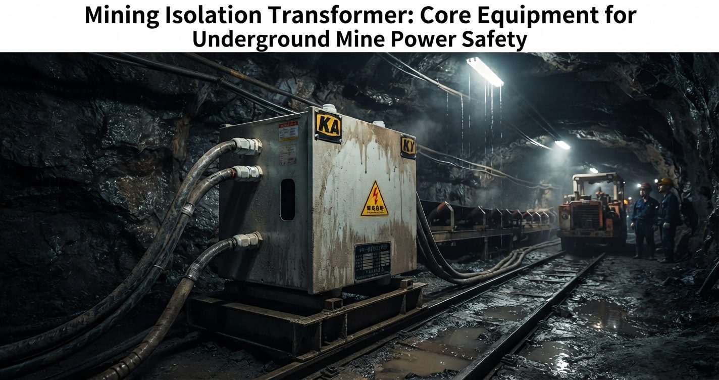
In hazardous-area installations classified under ATEX or IECEx regulations, isolation transformers provide an additional safety layer by limiting fault energy and preventing ignition-capable sparks in explosive atmospheres.
Data Centers and Telecommunications
Server rack isolation enables fault containment — a ground fault in one rack cannot propagate to adjacent systems when proper galvanic isolation exists between distribution zones. This architecture supports the redundancy requirements of Tier III and Tier IV facilities.
Ground-loop-induced data errors manifest as intermittent, difficult-to-diagnose problems that degrade network performance and data integrity. Isolation transformers eliminate these ground loops at the power distribution level, improving reliability across entire rack rows.
Integration with UPS architectures requires careful design. Isolation transformers placed downstream of UPS systems provide a clean reference point for the protected distribution system while maintaining the isolation boundary under all operating modes including bypass.
Laboratory and Research Environments
Sensitive measurement instrumentation — oscilloscopes, spectrophotometers, mass spectrometers — requires power free from earth leakage paths that introduce measurement errors. Even microamp-level leakage currents can corrupt readings in high-precision research.
Cleanroom power distribution benefits from isolation transformers that prevent ground-loop currents from flowing through equipment chassis, reducing electromagnetic emissions that could affect sensitive processes in semiconductor fabrication or pharmaceutical manufacturing.
| Application Sector | Typical kVA Range | Key Compliance Standard | Primary Benefit |
|---|---|---|---|
| Healthcare | 2–25 kVA | IEC 60601 / NFPA 99 | Patient safety, leakage current control |
| Industrial | 5–500 kVA | IEC 61558 | Equipment protection, noise filtering |
| Data Centers | 10–300 kVA | TIA-942 | Fault isolation, uptime |
| Laboratories | 1–15 kVA | IEC 61010 | Measurement accuracy |

Selection Criteria for Business Decision-Makers
Sizing and Load Calculation
The fundamental sizing parameter is apparent power in kVA, not real power in kW. Apparent power accounts for reactive loads (motors, capacitors) that draw current without performing useful work but still require transformer capacity. Confusing kW and kVA leads to undersized units and premature failure.
Inrush current on startup represents the most common sizing oversight. Motor loads can draw 6–8 times rated current for several cycles; capacitive loads (power supplies, UPS systems) present similar transient demands. The transformer must handle these peaks without saturating its core.
Apply derating factors for real-world conditions: reduce rated capacity by 1% for every degree Celsius above 40°C ambient, derate by 3–5% per 500 meters above 1000m altitude, and apply harmonic derating factors (K-factor) when serving nonlinear loads exceeding 15% total harmonic distortion.
Construction and Insulation Class
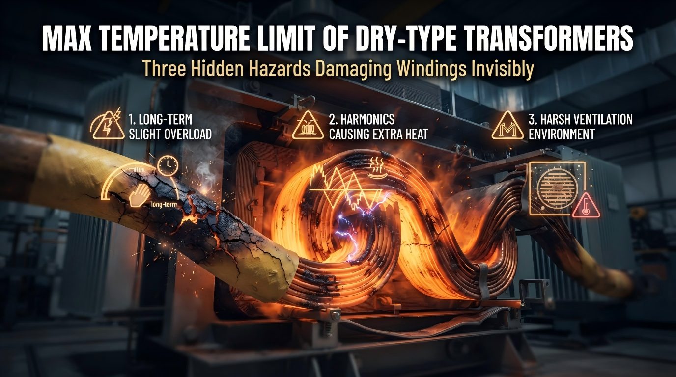
Insulation class directly determines service life at operating temperature. Class F (155°C) suits most standard applications, while Class H (180°C) provides additional thermal margin critical for continuous-duty installations or elevated ambient environments. Each 10°C reduction in operating temperature below the class rating approximately doubles insulation life.
Enclosure ratings must match the installation environment: IP21 suffices for clean indoor electrical rooms, IP54 handles dust-laden industrial environments, and IP65 or higher protects against washdown or outdoor exposure. Over-specifying enclosure rating wastes budget; under-specifying leads to premature insulation breakdown.
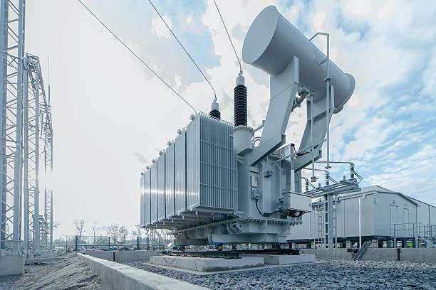
Dry-type construction dominates modern installations due to zero fire risk, no oil maintenance, and indoor suitability. Oil-filled units remain relevant only for very large outdoor installations (above 500 kVA) where superior cooling and lower weight-per-kVA justify the added maintenance and containment requirements.
Compliance and Certification Requirements
IEC 61558-2-1 serves as the baseline international safety standard for power transformers, covering construction, testing, and marking. All quality isolation transformers should demonstrate compliance through accredited third-party testing — not self-declaration alone.
Regional market access requires additional certifications: UL 5085 and CSA C22.2 for North America, CE marking for the European Economic Area, and RCM for Australia and New Zealand. Specifying a unit without the correct certification for your jurisdiction creates compliance risk and potential installation delays.
Always request third-party test reports from recognized bodies (TÜV, UL, Intertek, CSA). Manufacturers offering only self-declared conformity may not have undergone the rigorous type testing that validates safety claims under fault conditions.
Noise Attenuation and Shielding Specifications
Single Faraday shields provide adequate noise filtering for general industrial applications, achieving 100–120 dB common-mode rejection. Double electrostatic shields — one between primary and shield, one between shield and secondary — push rejection to 140 dB or higher for medical and laboratory use.
Common-mode rejection ratio (CMRR) should be specified at the frequencies of concern. A transformer rated at 140 dB CMRR at 60 Hz may only achieve 80 dB at 1 MHz. Discuss frequency-dependent performance with manufacturers when protecting equipment sensitive to high-frequency interference.
For ultra-sensitive loads such as electron microscopes, precision analytical instruments, or high-resolution ADC systems, coupling capacitance below 0.005 pF between primary and secondary ensures virtually zero capacitive noise transfer — but this specification comes at a significant cost premium.
| Parameter | Standard Grade | Medical/Premium Grade |
|---|---|---|
| Leakage Current | <300 µA | <50 µA |
| Shielding | Single Faraday | Double Faraday |
| CMRR | 120 dB | 140 dB+ |
| Insulation Class | F (155°C) | H (180°C) |
| Typical Cost Premium | Baseline | +35–60% |
| Compliance | IEC 61558 | IEC 60601 + IEC 61558 |
Total Cost of Ownership and ROI Analysis
Acquisition Cost Breakdown
Unit pricing for 240V isolation transformers varies significantly by capacity and grade. As of 2026, expect $1,800–$4,500 for units in the 2–10 kVA range, $4,500–$14,000 for 10–50 kVA, and $14,000–$85,000+ for industrial units from 50–500 kVA. Medical-grade units command a 35–60% premium over standard equivalents.
Installation costs encompass electrical contractor labor, switchgear modifications to accommodate the transformer, dedicated circuit breakers, and commissioning. Budget $2,000–$4,500 for units under 50 kVA and $5,000–$15,000 for larger installations requiring structural support or ventilation modifications.
Essential accessories add to the initial investment: bypass switches for maintenance continuity ($500–$2,000), temperature monitoring relays ($300–$800), and forced-ventilation systems for enclosed installations ($400–$1,500).
Operational Cost Factors
Modern isolation transformers achieve 96–99% efficiency at rated load. A 50 kVA unit operating at 97% efficiency loses approximately 1.5 kW continuously, translating to roughly $320 per year in energy costs at average commercial electricity rates. Over a 20-year lifespan, cumulative energy loss costs $6,000–$8,000 — modest relative to the equipment value being protected.
Maintenance demands are minimal for dry-type units: annual visual inspection, insulation resistance testing every 1–3 years, and periodic thermal imaging to detect developing hot spots. Total annual maintenance cost rarely exceeds $200–$400 when incorporated into existing electrical maintenance programs.
Expected service life with proper derating and maintenance is 25–30 years. Units operated consistently within their thermal ratings and protected from excessive harmonics frequently exceed 30 years, making isolation transformers among the longest-lived components in an electrical distribution system.
Cost of NOT Installing — Risk Quantification
Unplanned downtime costs vary by industry but are universally significant. Manufacturing facilities report average losses of $260,000 per hour of unplanned stoppage. Healthcare facilities face compliance penalties, potential litigation, and reputational damage that can exceed $500,000 per serious incident.
Equipment replacement costs from voltage transients and ground faults accumulate rapidly. A single event damaging a PLC rack ($15,000–$40,000), a CNC servo drive ($8,000–$25,000), or laboratory instrumentation ($50,000–$500,000) can exceed the entire cost of an isolation transformer installation.
Insurance underwriters increasingly recognize isolation transformers as risk mitigation infrastructure. Facilities demonstrating comprehensive electrical protection strategies — including proper isolation — report premium reductions of 5–15% on equipment insurance, creating ongoing financial returns beyond direct protection value.
| Cost Element | With Isolation Transformer | Without (Direct Mains) |
|---|---|---|
| Capital Investment | $8,500–$14,000 | $0 |
| Installation | $2,000–$4,500 | $0 |
| Annual Energy Loss | ~$320/yr | $0 |
| Avg. Equipment Damage (5yr) | $1,200 | $38,000–$75,000 |
| Downtime Costs (5yr) | Minimal | $15,000–$120,000 |
| Net 5-Year Position | $12,100–$20,100 | $53,000–$195,000 |

Installation Best Practices
Electrical Design Considerations
Position the isolation transformer as close to the protected load as practical to minimize secondary cable runs and associated voltage drop. Keep secondary cable lengths below the point where voltage drop exceeds 3% at full rated current — for a 50 kVA unit at 240V (208A), this typically limits runs to 20–30 meters without upsizing conductors.
Cable sizing must account for the transformer's rated secondary current plus derating for installation method, ambient temperature, and grouping. Oversizing cables by one standard size beyond calculated minimums provides margin for future load growth without requiring recabling.
Secondary winding grounding configuration determines the protection philosophy. TN-S systems (one point grounded) provide conventional fault protection via overcurrent devices. IT systems (ungrounded secondary) maximize continuity by allowing operation with the first fault — standard practice in operating theatres and critical process control — but require insulation monitoring devices to detect and alert on degraded conditions.
Environmental and Physical Requirements
Dry-type isolation transformers require minimum ventilation clearances of 100mm on all sides and 300mm above for natural convection cooling. Restricted airflow causes hot-spot temperatures to exceed insulation class ratings, accelerating degradation and reducing service life dramatically.
Acoustic noise from core magnetostriction typically ranges from 40–55 dB at one meter. For installations near occupied spaces, specify low-noise cores (grain-oriented silicon steel, step-lap construction) and consider vibration isolation mounting to prevent structural noise transmission.
Ensure accessibility for maintenance and thermal monitoring. Infrared windows or clear sight lines to terminations and core surfaces enable predictive maintenance without de-energizing the transformer — a significant advantage for facilities that cannot tolerate planned shutdowns.
Commissioning and Testing Protocol
Factory acceptance testing (FAT) should verify all nameplate ratings, including no-load losses, full-load losses, impedance voltage, insulation resistance, and applied voltage withstand. Witnessing FAT or reviewing certified results provides confidence before the unit ships to site.
Site acceptance testing (SAT) after installation confirms that transportation and installation have not damaged the unit. Minimum tests include insulation resistance measurement (should exceed 100 MΩ at 1000V DC for new units), turns ratio verification, and phase rotation confirmation for three-phase units.
Establish baseline thermal images during the first week of loaded operation. These reference images become invaluable for future predictive maintenance, revealing developing faults as thermal anomalies long before they progress to failure.

Common Misconceptions Decision-Makers Should Avoid
"Any Transformer Provides Isolation"
This is false and potentially dangerous. Autotransformers share a common winding between input and output — there is no galvanic separation, no fault path interruption, and no safety isolation. Variable transformers (variacs) similarly offer no isolation despite providing voltage adjustment.
Only transformers with physically separate, independently insulated primary and secondary windings provide true galvanic isolation. Specifying an autotransformer where isolation is required creates a direct safety hazard and violates every applicable standard for isolated power systems.
"Isolation Transformers Eliminate All Power Problems"
Isolation transformers excel at addressing common-mode noise, ground faults, DC leakage, and transient coupling between circuits. They do not protect against sustained overvoltage, frequency variations, extended outages, or differential-mode disturbances that appear between line and neutral.
A comprehensive power protection strategy typically layers complementary technologies: surge protective devices (SPDs) for high-energy transients, uninterruptible power supplies (UPS) for outage ride-through, and voltage regulators for sustained supply variations. The isolation transformer provides the foundation — not the entire solution.
"Bigger Is Always Better"
Oversizing carries real penalties. Transformers operating at 20–30% of rated capacity exhibit significantly lower efficiency (92–94% versus 97–99% at optimal loading), meaning higher energy losses for no additional protection benefit. The excess capacity also represents wasted capital and unnecessary floor space.
Right-sizing methodology targets 60–80% loading at normal operating conditions, providing headroom for inrush and short-term overloads without the efficiency and cost penalties of gross oversizing. Calculate actual load, add 20–25% margin, and select the nearest standard kVA rating.
Frequently Asked Questions
What is the difference between an isolation transformer and a step-down transformer?
A step-down transformer changes voltage level — for example, converting 415V to 240V — using a turns ratio greater than 1:1. An isolation transformer maintains the same voltage on both sides (240V input, 240V output) using a 1:1 turns ratio. Its purpose is galvanic isolation: creating a complete electrical break between primary and secondary circuits for safety and noise filtering, not voltage conversion.
Can a 240V isolation transformer protect against electric shock?
It significantly reduces shock risk under single-fault conditions by eliminating the direct earth-return path. If a person contacts one pole of the isolated secondary, no current flows because there is no circuit back to earth. However, simultaneous contact with both poles remains hazardous. Isolation transformers complement — but do not replace — RCDs, GFCIs, and proper earthing practices.
How do I determine the correct kVA rating for my application?
Sum the apparent power (VA) of all connected loads using nameplate ratings or measured current draw. Add20–25% headroom for inrush currents and future expansion. Apply derating factors for ambient temperatures above 40°C, altitude above 1000m, and harmonic-rich environments (K-factor rating). Select the nearest standard kVA rating above your calculated figure — common sizes include 1, 2, 3, 5, 7.5, 10, 15, 25, 50, 75, 100, and 150 kVA.
Do isolation transformers waste significant energy?
Modern units operate at 96–99% efficiency at rated load, making energy losses minimal in context. A 50 kVA isolation transformer operating at 97% efficiency loses approximately 1.5 kW continuously, costing roughly $250–$400 per year in electricity. Over a 25-year service life, total energy cost is $6,000–$10,000 — a fraction of the value of the equipment and uptime being protected.
Is an isolation transformer required by code in medical facilities?
In most jurisdictions, yes. NFPA 99 (United States) mandates isolated power systems in wet procedure locations and critical care areas. AS/NZS 3003 (Australia and New Zealand) requires them in patient treatment areas. IEC 60364-7-710 provides the international framework mandating medical IT systems with isolation transformers in Group 2 medical locations. Non-compliance creates both regulatory and patient-safety liability.
What maintenance does a 240V isolation transformer require?
Dry-type isolation transformers require minimal ongoing maintenance: annual visual inspection for dust accumulation, discoloration, or physical damage; insulation resistance testing every 1–3 years (values should remain above 100 MΩ); periodic thermal imaging to identify developing hot spots; and verification that ventilation clearances remain unobstructed. There are no oils to change, no filters to replace, and no consumable components under normal operating conditions.
Take the Next Step: Protect Your Critical Infrastructure
Specifying the right 240V isolation transformer requires clarity on four decision points: your application requirements and applicable standards, proper load sizing with adequate margin, the shielding and construction grade your equipment demands, and a clear-eyed view of the ROI case that justifies the investment to stakeholders.
The data is unambiguous. A properly specified isolation transformer costing $10,000–$20,000 installed protects against $50,000–$200,000 in potential equipment damage and downtime over five years. The payback period in high-criticality environments is often measured in months, not years.
Recommended immediate actions:
Request a site-specific power quality assessment from a qualified electrical engineer to identify vulnerability points in your distribution system and quantify your exposure to ground faults, transients, and noise.
Develop an internal specification document using the selection criteria outlined in this guide — kVA sizing, shielding requirements, compliance standards, and environmental ratings — to ensure your procurement process evaluates suppliers on the parameters that matter.
Engage certified transformer manufacturers directly for application-specific recommendations. Reputable manufacturers provide detailed technical consultation, compliance documentation, and test reports that support your internal approval process.
Every day that critical equipment operates without proper galvanic isolation is a day your organization carries preventable risk on its balance sheet. The specification process starts with a single conversation — initiate it today.