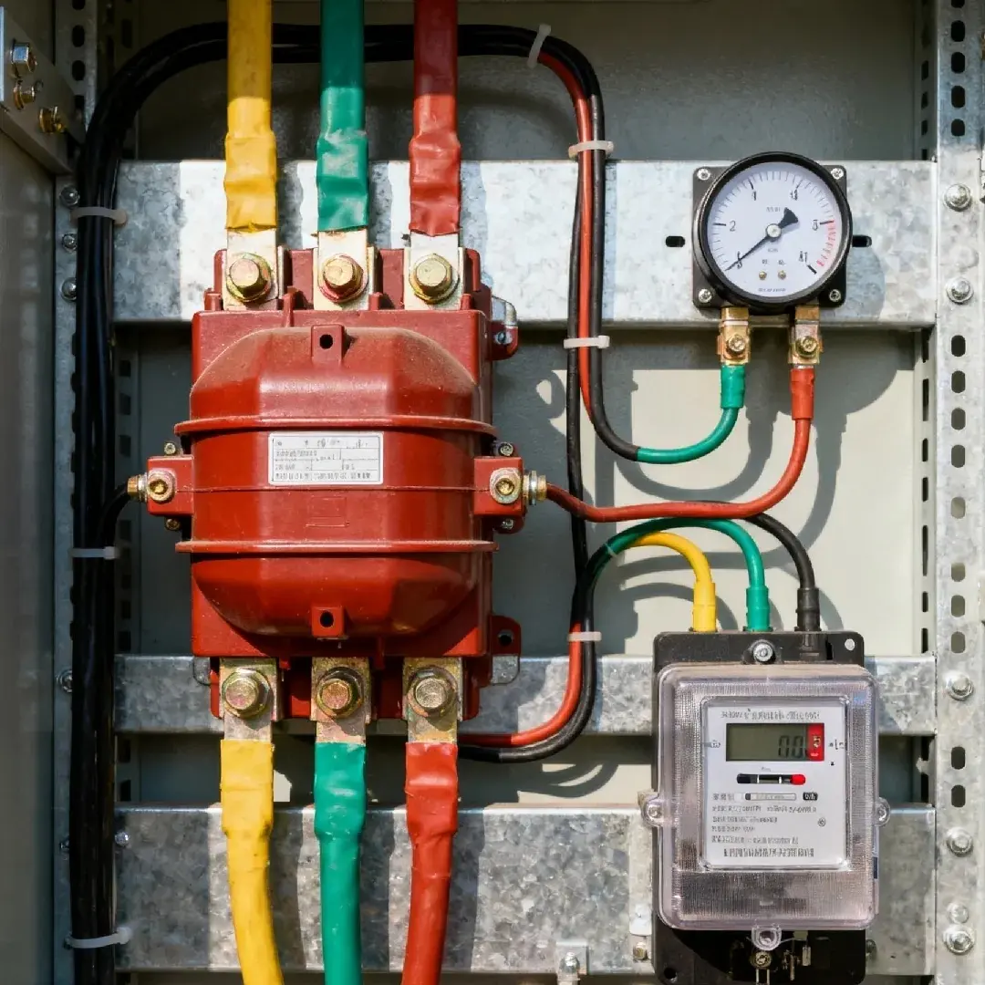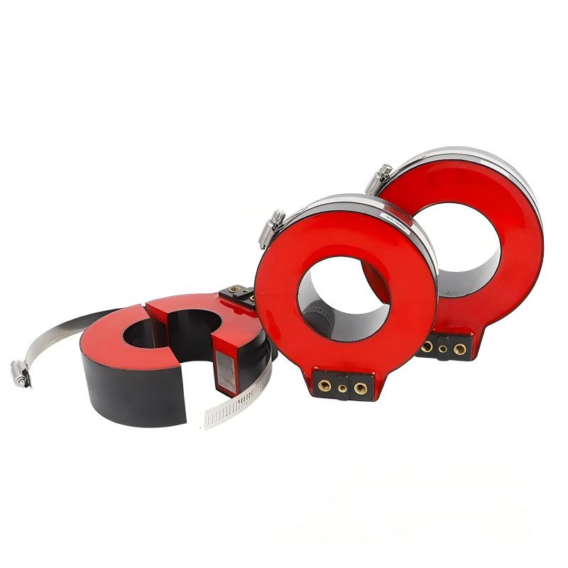
When a switchgear panel is already crowded, every extra bend in a cable, every added mounting bracket, and every extra shutdown hour costs money. That is exactly why the donut current transformer has become a preferred solution in modern low-voltage and medium-voltage distribution projects.
In practical terms, a donut current transformer is the engineer’s answer to a common field problem: how to measure or protect a circuit accurately without redesigning the main conductor route. Instead of forcing the current path through a complicated built-in primary winding, the cable or busbar simply passes through the center opening.
This sounds simple, but in real commercial and industrial projects, that simplicity has major consequences. It reduces panel congestion, shortens assembly time, improves retrofit feasibility, and supports both metering and protection functions when selected correctly.
In industrial terminology, this product is commonly referred to as a through-core current transformer or donut-shaped toroidal current transformer. For export projects, buyers may also name it window-type CT, ring-type current transformer, or toroidal current transformer.
Why Donut CTs Matter in Modern Switchgear
Modern LV and MV switchgear is expected to do more than basic power distribution. It must support energy management, branch-level metering, protective relays, motor monitoring, building automation, PV integration, EV charging, and remote data acquisition.
That creates a measurement challenge. Panels become denser, conductor routes become tighter, and there is less tolerance for bulky components that complicate busbar or cable installation.
A donut CT solves this by using a pass-through primary conductor. No internal primary winding is required. The installer passes the cable or copper bar through the center window, and the CT converts the primary current into a standard secondary signal, typically 1A or 5A, for a meter, relay, or controller.
For OEM panel builders, this means faster assembly. For retrofit contractors, it means fewer modifications. For facility owners, it means lower shutdown risk and better data visibility.
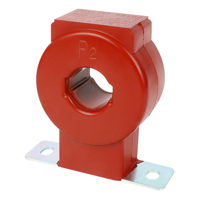
The Real Problem: Measurement, Protection, and Retrofit Constraints
Traditional wound current transformers can be effective, but they are not always convenient in crowded commercial or industrial switchboards. Their structure may require more installation planning, more conductor termination work, or more panel space than the project can afford.
In retrofit jobs, the situation is even harder. If a factory wants to add branch metering to an old switchboard, disconnecting and re-routing main feeders may cause production interruption. In some sectors, one hour of downtime can cost far more than the hardware itself.
Consider three common field scenarios:
Commercial buildings: Energy managers need tenant sub-metering, but existing riser and feeder arrangements leave little room for rewiring.
MCC motor systems: Maintenance teams want real-time current monitoring for pumps, fans, and compressors, yet the original panel was never designed for advanced instrumentation.
PV and ESS projects: Integrators need clean current signals for inverter monitoring and export control inside compact cabinets.
In all three cases, donut CTs reduce installation complexity because they work with the conductor as it already exists. This is the practical value behind the growing demand for donut CT installation in LV switchgear and related retrofits.
What Is a Donut Current Transformer?
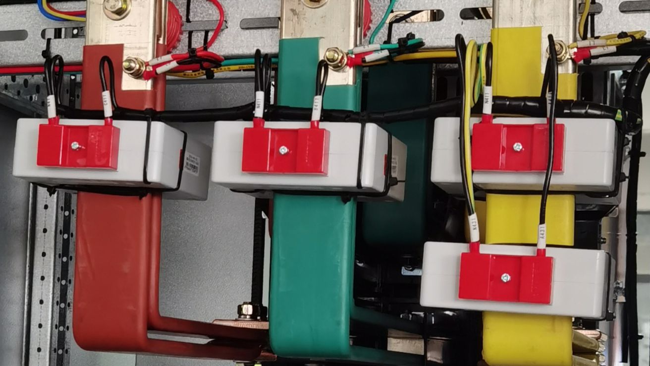
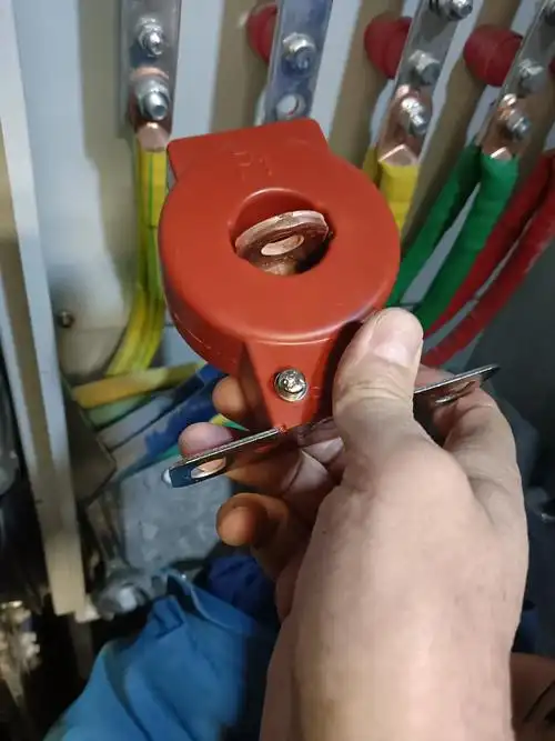
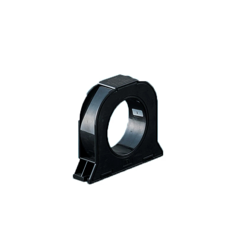
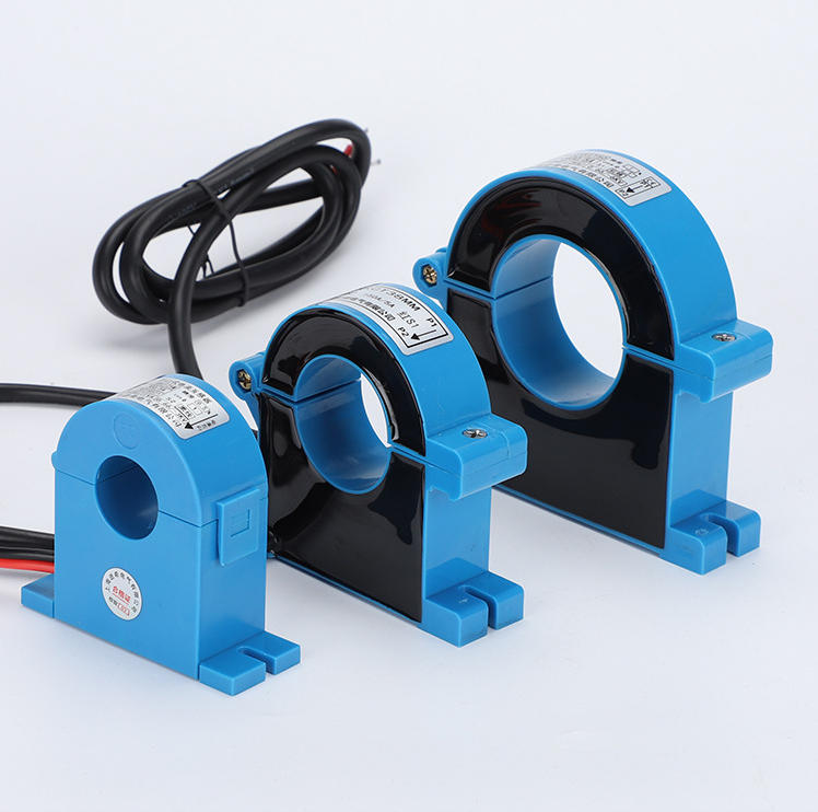
A donut current transformer is a ring-type, window-type, or toroidal current transformer in which the primary conductor passes through the center opening of the CT.
Its external form is a complete circular ring with a hollow center. The primary side has no built-in winding in the usual sense. Instead, the cable or busbar threaded through the hole acts as the primary winding.
Inside the CT body, a magnetic core carries a secondary winding. Through electromagnetic induction, the transformer converts a large primary current, often from tens to thousands of amperes, into a standardized smaller secondary current for metering or protection devices.
This structure is especially common in:
Low-voltage switchboards
GGD panels
MCC motor control centers
Smart metering cabinets
Busbar monitoring systems
Indoor substations and package substations
PV, ESS, UPS, and EV charging cabinets
Closed-Core vs Split-Core Donut CT
Closed-core donut CTs are one-piece ring units. The conductor must be inserted through the window during assembly. This design provides the best magnetic continuity and usually the highest accuracy.
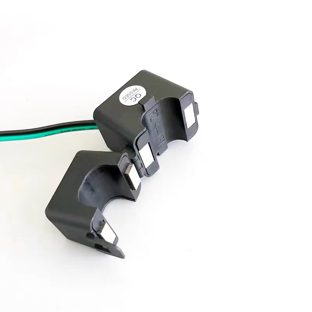
Split-core donut CTs, also called flexible opening or split-core toroidal CTs, can open and close around an existing cable or bar. Their main advantage is that they can be added to an existing circuit without removing or disconnecting the main conductor.
In commercial terms, the choice is straightforward:
Closed-core: best for new switchgear, best accuracy, stronger metering performance.
Split-core: best for retrofit, no-shutdown installation potential, easier field upgrade.
For export projects, many buyers use both types in one product family: closed-core units for new production panels, and split-core units for site upgrades or old circuit renovation.
Donut Current Transformer Working Principle
The donut current transformer working principle is based on electromagnetic induction. When alternating current flows through the primary conductor passing through the CT window, it creates a magnetic field in the toroidal core.
This changing magnetic field induces current in the secondary winding. The induced secondary current is proportional to the primary current according to the CT ratio.
For example:
A 200/5A CT means 200A on the primary corresponds to 5A on the secondary at rated conditions.
A 1000/1A CT means 1000A primary corresponds to 1A secondary.
The secondary output is then connected to an energy meter, multifunction meter, power quality analyzer, relay, PLC input module, or other monitoring equipment.
This design is highly practical because it allows the CT to sense large currents without carrying those large currents through the meter or relay itself.
How the Primary Conductor Becomes One Turn
Each conductor passing once through the donut window is effectively one primary turn.
If the cable is looped through the CT window multiple times, the number of primary turns increases. This changes the effective ratio and can improve measurement resolution in lower-current applications.
For example, suppose a CT is rated 100/5A:
1 primary turn: 100A primary gives 5A secondary.
2 primary turns: 50A line current behaves like 100A ampere-turns to the CT.
4 primary turns: 25A line current behaves like 100A ampere-turns.
This is one of the most commercially useful advantages of a toroidal CT. A single model can serve different lower-current applications by changing the number of passes, provided window size, heating, and installation constraints are respected.
Why Closed Magnetic Circuits Improve Accuracy
The toroidal structure forms a closed magnetic circuit. This reduces leakage flux compared with less optimized magnetic paths.
Lower magnetic leakage improves measurement stability and accuracy. That is why closed-core donut CTs are widely used in metering-grade applications, with achievable classes such as 0.2S and 0.5 when the design, burden, and installation conditions are correct.
In practical projects, this matters because a small measurement error repeated over thousands of operating hours directly affects billing, energy analysis, and process benchmarking.
Donut CT Construction and Core Design
A standard donut CT typically includes the following elements:
Toroidal magnetic core: usually high-permeability material to support accurate induction.
Insulated secondary winding: wound around the core and designed for the required ratio and class.
Center window: allows cable or busbar pass-through.
Outer enclosure: provides electrical insulation and mechanical protection.
Terminal arrangement: secondary terminals for meter or relay connection.
Polarity marking: indicates orientation for correct phase relationship.
In LV and MV switchgear assemblies, the enclosure material and terminal form vary by project. Some are compact molded units for switchboards. Others are designed for busbar chambers, cable compartments, or retrofit kits.
Engineering teams should also pay attention to thermal performance, insulation level, mounting hardware, and whether the design is optimized for cable use, flat copper bars, or both.
Donut CT Installation in LV Switchgear
Donut CT installation in LV switchgear is one of the main reasons this product is so widely used. In low-voltage switchboards, the installer simply routes the feeder cable or busbar through the CT opening and secures the CT in position.
This is ideal for:
GGD cabinets
MCC motor control centers
Main distribution boards
Feeder pillars
Smart metering cabinets
Busbar trunking monitoring points
Compared with more complex alternatives, the workflow is cleaner and often faster. That is why ring CTs remain a standard choice in many low-voltage assembly lines.
Pre-Installation Checklist
Before installation, check the following items carefully. Most field errors come from specification mismatch, not from the CT itself.
Window size: confirm the inner diameter or opening dimensions fit the cable or busbar with installation clearance.
Conductor diameter: include insulation, not just copper size.
Busbar dimensions: width, thickness, spacing, and movement tolerance matter.
CT ratio: select based on expected maximum operating current, not only nominal load.
Accuracy class: metering and protection require different performance targets.
Burden: include meter input burden plus cable lead burden.
Frequency: typically 50Hz or 60Hz, according to project location.
Mounting space: verify clearance to panel structure, cable bends, and terminal access.
Secondary output: 1A or 5A must match the receiving device.
Shorting method: ensure safe secondary shorting before energization or maintenance.
Step-by-Step Installation Process
Good installation is simple, but it must still be disciplined. The following sequence reflects standard field practice for LV panels.
Verify the drawing and label. Confirm ratio, class, burden, polarity, and the target circuit.
Mount the CT securely. Fix it to the support plate, busbar structure, or designated bracket.
Pass the conductor through the center window. For cable feeders, keep the conductor as centered as practical.
Check polarity orientation. Ensure primary and secondary polarity marks align with the metering or relay scheme.
Connect the secondary wiring. Use the correct terminal identification and maintain neat routed wiring.
Ground according to the design. Many schemes require one point of secondary grounding for safety.
Keep the secondary shorted until the receiving device is connected. This is a critical safety rule for CTs.
Test continuity and insulation as required. Verify no loose terminals or wiring mistakes.
Energize and validate readings. Compare phase current values with known load conditions if possible.
Common LV Installation Mistakes to Avoid
These are the mistakes that repeatedly appear in site troubleshooting.
Wrong polarity: can cause reverse power indication, relay malfunction, or poor data quality.
Undersized window: forces poor conductor routing or impossible installation.
Open-circuit secondary: dangerous and potentially damaging to the CT.
Excessive burden: reduces accuracy and may saturate the CT earlier than expected.
Poor cable centering: may affect repeatability in some precision applications.
Using a metering CT for protection duty without checking class: can compromise fault performance.
Ignoring cable lead length: extra wire resistance adds burden.
Donut CT Installation in Medium Voltage Switchgear
Medium voltage switchgear current transformer applications often involve measurement and protection circuits tied to MV systems, but the donut CT itself is commonly installed in accessible cable sections, control compartments, or low-voltage auxiliary areas associated with the panel.
In many practical projects, donut CTs are used on the low-voltage side of package substations, on auxiliary measurement points, or in cable compartments where installation and maintenance can be managed safely.
In MV-linked systems, engineering discipline becomes more important. The issue is not only ratio and class, but also compartment arrangement, insulation coordination, and access restrictions.
Safety and Insulation Considerations in MV Panels
When specifying donut CTs for MV-related switchgear applications, engineers should review more than just current rating.
Clearance and creepage distances: these must meet project and standard requirements.
Compartment separation: measurement components should be placed in suitable sections.
Shielded cable routing: secondary leads should be protected from noise and interference where necessary.
Insulation coordination: confirm compatibility with panel design and system environment.
Mechanical positioning: avoid stress from cable movement or thermal expansion.
For export-oriented switchgear, project consultants often ask for documented test capability, insulation verification, polarity marking, and dimensional drawings before approving the CT configuration.
When to Use Split-Core Donut CT for Retrofit Projects
Split-core donut CTs are especially valuable in retrofit projects where shutdown is difficult or expensive.
Typical examples include:
Old switchboards in commercial buildings
Existing busway systems in factories
Live feeder monitoring upgrades
Energy management retrofits in occupied facilities
Temporary monitoring installations for load surveys
In one common retrofit model, a contractor installs split-core CTs on existing branch feeders during a planned short maintenance window, avoiding the far more disruptive work of disconnecting and re-terminating main conductors.
That is why split-core toroidal CTs are not just a convenience product. In many projects, they are the only commercially acceptable route to adding measurement capability.
Ring Type Current Transformer for Protection and Metering
A ring-type current transformer for protection and metering can support both functions, but only when the specification fits the application.
Many buyers make a costly assumption that any CT can do both jobs equally well. In reality, metering and protection place different demands on the transformer.
Metering CTs prioritize accuracy in the normal operating range. Protection CTs must maintain useful performance during abnormal current conditions so relays can respond correctly.
In some projects, separate CTs are used for metering and protection. In others, a carefully selected product family supports both roles across different feeders.
Metering Applications
Donut CTs are widely used for energy data acquisition in commercial and industrial systems.
Multifunction meters: current input for panel-level electrical data.
Smart energy meters: billing and sub-billing applications.
Tenant sub-metering: shopping malls, offices, and industrial parks.
EV charging stations: feeder current measurement and usage analysis.
PV grid connection: inverter output and export monitoring.
Building energy monitoring: integration with BA and IoT platforms.
For these uses, accuracy class and low burden error are critical. A metering-grade closed-core CT is often preferred for new assemblies.
Protection Applications
Donut CTs also play an important role in protective and supervisory circuits.
Overload protection
Short-circuit detection
Earth leakage or residual current schemes
Phase imbalance monitoring
Motor current supervision for pumps, fans, and compressors
In MCC environments, motor current trends can indicate mechanical problems, blocked filters, pump cavitation, bearing deterioration, or abnormal process loading. Reliable CT data helps maintenance teams move from reactive repair to preventive maintenance.
Medium Voltage Switchgear Current Transformer Applications
Medium voltage switchgear current transformer applications linked to donut CT technology usually focus on measurement and signaling points connected to larger distribution systems.
Common applications include:
Indoor substations: LV outgoing feeders and auxiliary monitoring.
Package substations: transformer secondary side current measurement.
Ring main unit-related auxiliary circuits: monitoring associated distribution paths.
Generator synchronization systems: current feedback for parallel operation and supervision.
Energy storage system cabinets: inverter and AC collection monitoring.
Industrial feeder systems: branch analysis, demand tracking, and relay inputs.
In many cases, the CT is physically installed in a low-voltage control or cable section, but the measurements support decisions affecting medium-voltage operations and asset loading.
Low Voltage and Medium Voltage CT Selection Guide
A proper low voltage and medium voltage CT selection guide must go beyond current ratio alone. Buyers who select only by ampere rating often face avoidable issues later: poor fit, unstable readings, relay mismatch, or retrofit failure.
The core selection framework should cover the following:
Primary current range: nominal and maximum expected load.
Secondary current: 1A or 5A according to meter or relay input.
Window size: must fit conductor dimensions with assembly clearance.
Accuracy class: 0.2S, 0.5, 1.0, or protection class depending on need.
Burden: receiving device plus lead length.
Frequency: 50Hz or 60Hz.
Installation type: closed-core or split-core.
Application: metering, protection, or dual-purpose design logic.
Insulation and environment: panel conditions, temperature, and project standards.
Key Selection Criteria Table
| SELECTION ITEM | WHAT TO CHECK | WHY IT MATTERS | TYPICAL RECOMMENDATION |
|---|---|---|---|
| Ratio | Maximum operating current and overload margin | Prevents under-range or saturation issues | Choose based on real load profile, not only breaker frame size |
| Accuracy Class | Metering vs protection requirement | Determines usable precision or relay behavior | 0.2S/0.5 for metering, protection class for relay duty |
| Burden | Meter/relay input plus cable lead resistance | Higher burden reduces performance | Keep secondary wiring short and correctly sized |
| Window Size | Cable OD or busbar dimensions | Affects installation feasibility and conductor centering | Add clearance for insulation and assembly tolerance |
| Conductor Type | Single cable, multiple cables, or copper bar | Influences fit and magnetic symmetry | Verify actual site geometry before ordering |
| Application | Metering, monitoring, protection, retrofit | Changes class, output, and core choice | Separate specifications where function differs |
| Core Type | Closed-core vs split-core | Impacts accuracy and installation method | Closed-core for new panels, split-core for retrofit |
| Frequency | 50Hz or 60Hz system | Affects design matching | Match local grid standard |
Recommended Selection by Use Case Table
| USE CASE | TYPICAL RATIO | PREFERRED CLASS | OUTPUT | RECOMMENDED TYPE | NOTES |
|---|---|---|---|---|---|
| LV feeder metering | 100/5A to 800/5A | 0.5 or 0.2S | 5A or 1A | Closed-core | Best for panel factory assembly and billing accuracy |
| MCC motor feeders | 50/5A to 400/5A | 1.0 or suitable protection class | 5A | Closed-core or split-core | Depends on new build or retrofit monitoring |
| PV systems | 100/5A to 2500/1A | 0.5 | 1A often preferred | Closed-core | Useful for inverter output and export measurement |
| EV charging distribution | 100/5A to 600/5A | 0.5 | 5A | Closed-core or split-core | Branch metering often added later |
| Building energy monitoring | 60/5A to 1000/5A | 0.5 | 5A | Split-core for retrofit | Helps avoid shutdown in occupied buildings |
| MV auxiliary measurement points | Project-specific | Metering or protection as required | 1A or 5A | Closed-core mostly | Must check insulation, compartment, and wiring design |
Real-World Data and Application Examples
Authoritative selection advice should be grounded in field use, not theory alone. Below are practical examples based on common commercial and industrial conditions.
Across retrofit energy projects, branch feeder measurement additions often reduce blind spots in consumption analysis. In many facilities, the first year of sub-metering reveals that 10% to 25% of circuits consume significantly more energy than previously assumed due to imbalance, standby waste, or process drift.
Similarly, in motor-intensive systems, current trend monitoring often detects early abnormal loading before operators notice process failure. A pump drawing 15% to 20% above its historical current baseline can indicate blockage, mechanical wear, or abnormal hydraulic resistance.
Example Table: Typical Donut CT Use Cases
| APPLICATION | TYPICAL PRIMARY CURRENT | COMMON SECONDARY OUTPUT | TYPICAL ACCURACY CLASS | PANEL TYPE |
|---|---|---|---|---|
| Factory sub-metering feeder | 100A to 630A | 5A | 0.5 | LV switchboard / GGD |
| MCC motor monitoring | 30A to 300A | 5A | 1.0 or protection class | MCC cabinet |
| PV inverter AC output | 250A to 2000A | 1A or 5A | 0.5 | PV combiner / AC cabinet |
| EV charging feeder | 60A to 400A | 5A | 0.5 | Distribution cabinet |
| Building retrofit branch circuits | 40A to 250A | 5A | 0.5 to 1.0 | Existing panel with limited access |
| ESS AC collection | 400A to 3200A | 1A | 0.5 | Energy storage cabinet |
Example: Factory Energy Sub-Metering Retrofit
A manufacturing plant with three aging switchboards wanted branch-level energy visibility for production cost allocation. The challenge was that the facility could not afford a full-day shutdown to disconnect major feeders.
The retrofit team used split-core donut CTs on existing branch cables and connected them to a multifunction metering gateway. Installation was completed in short maintenance windows rather than a major outage.
The result was commercially meaningful. Within one quarter, the plant identified a packaging line whose night-shift idle consumption was nearly double the expected baseline. That single visibility improvement justified the measurement upgrade.
This is where split-core toroidal CTs show their real value. They reduce shutdown time, simplify field labor, and make branch-level metering feasible in old infrastructure.
Example: MCC Motor Monitoring for Pumps and Fans
In an MCC serving pumps and ventilation fans, donut CTs were installed on motor feeders to provide continuous current feedback to the local monitoring system.
Over several months, operators observed that one pump motor consistently drew 12% to 18% higher current than two parallel units operating under similar conditions. Inspection later confirmed mechanical drag and impeller fouling.
This kind of monitoring does not require exotic hardware. A properly specified ring type current transformer, connected to a meter or PLC, can provide enough trend data to support preventive maintenance decisions.
For many industrial users, the business benefit is not only protection. It is reduced unplanned downtime and more predictable maintenance scheduling.
Example: PV and Energy Storage Grid Connection
In PV inverter cabinets and energy storage AC collection systems, donut CTs are commonly used to monitor export current, inverter output, and feeder loading.
These measurements support:
Inverter performance monitoring
Export limitation control
Energy accounting
Power quality analysis
Grid interconnection supervision
In one typical configuration, closed-core donut CTs with 1A secondary outputs are selected for long secondary lead runs because lower current output can reduce wiring losses in certain system designs.
Suppliers such as Weisho Electric are often evaluated on whether they can provide not only the CT itself, but also ratio guidance, window sizing support, and documentation suitable for switchgear export projects.
Advantages of Donut CTs in Commercial and Industrial Projects
The popularity of donut CTs is not driven by marketing language. It is driven by project economics and installation practicality.
Simple installation: cable or busbar passes directly through the CT.
Compact structure: well suited to crowded panels.
High accuracy: especially in closed-core metering-grade versions.
Flexible ratio adaptation: multiple primary turns can adjust effective ratio.
Strong retrofit suitability: split-core models support upgrades without major disassembly.
Wide application range: metering, monitoring, relay input, building automation, PV, ESS, EV, UPS, marine, and rail-related cabinets.
For OEMs, these benefits reduce assembly labor. For EPC contractors, they reduce site complexity. For end users, they improve data access with lower disruption.
Limitations and Engineering Considerations
No CT type is perfect for every scenario. Donut CTs are highly versatile, but buyers should understand the engineering limits.
Open-circuit secondary risk: like all CTs, the secondary must never be left open under load.
Burden sensitivity: excessive cable length or device burden reduces performance.
Harmonic environments: nonlinear loads can affect measurement interpretation.
Space constraints: the window must fit the real conductor path, not the theoretical drawing only.
Split-core accuracy tradeoff: opening joints may reduce accuracy compared with closed-core versions.
Application mismatch: metering and protection requirements are not automatically interchangeable.
The key point is simple: the donut CT is easy to install, but it still demands proper engineering selection.
Standards, Testing, and Quality Points Buyers Should Verify
Professional buyers should ask for more than a quotation sheet. To protect project quality, verify the following points before approval.
Ratio accuracy: documented class performance under specified burden.
Polarity marking: clear and consistent terminal identification.
Insulation level: suitable for the intended assembly and project requirements.
Frequency rating: correct for 50Hz or 60Hz systems.
Burden rating: aligned with actual instrument and lead conditions.
Dimensional drawings: critical for window fit and mounting.
Test reports: especially important in export-oriented switchgear projects.
Production consistency: important when ordering for multi-panel or multi-site deployment.
Experienced manufacturers and project suppliers should be able to explain not only the catalog data, but also the application boundaries. That level of response is part of what separates a trading quote from real technical support. For many buyers, that is one reason they compare suppliers like Weisho Electric on both engineering communication and product consistency.
FAQ
What is a donut current transformer?
A donut current transformer is a ring-type, window-type, or toroidal CT in which the primary conductor passes through the center opening, while the internal secondary winding converts the primary current into a standard smaller output such as 1A or 5A.
How does a Donut CT work?
It works by electromagnetic induction. The cable or busbar passing through the CT acts as the primary winding, creating magnetic flux in the toroidal core, which induces a proportional current in the secondary winding.
What is the difference between closed-core and split-core Donut CT?
Closed-core Donut CTs are one-piece units with higher magnetic integrity and usually better accuracy. Split-core Donut CTs can open and close around existing conductors, making them ideal for retrofit and no-shutdown installation, though they may have a lower accuracy ceiling than closed-core versions.
Can a Donut CT be installed without disconnecting the main cable?
Yes, split-core models can usually be installed around existing conductors without disconnecting the main cable, subject to site safety rules, access conditions, and local electrical procedures.
Where are Donut CTs used in LV switchgear?
They are commonly used in GGD panels, MCCs, smart meter cabinets, branch feeder metering, busbar monitoring, multifunction metering points, and building energy monitoring systems.
Are Donut CTs used in medium voltage switchgear?
Yes, they are used in measurement and protection circuits associated with medium-voltage systems, often on accessible cable sections, auxiliary compartments, transformer secondary circuits, or control-related areas tied to MV distribution.
How do I select the right CT ratio and window size?
Start with the maximum expected load current, then match the CT ratio to the application range. After that, confirm the window size against the real conductor dimensions including insulation, and verify burden, accuracy class, secondary output, and whether the use is for metering, protection, or retrofit.
Is a Donut CT suitable for both metering and protection?
It can be, but only if the correct class and specification are selected for the intended duty. Metering and protection impose different performance requirements, so the CT must be chosen accordingly.
What happens if the CT secondary is left open?
If the CT secondary is left open while primary current is flowing, dangerous voltage can build up across the secondary terminals. This can damage the CT, threaten connected equipment, and create a serious safety hazard.
Can one Donut CT ratio be changed by looping the cable through multiple turns?
Yes. Each pass through the window adds one primary turn, so looping the conductor multiple times changes the effective ratio and can improve usability for lower-current measurement applications, provided space and thermal limits are respected.
Request a Donut CT Selection Recommendation
If you are selecting a donut current transformer for a new switchgear project or a retrofit job, do not rely on ratio alone.
Share your switchgear type, system voltage, current range, conductor size, required accuracy class, secondary output, and whether the project is new-build or retrofit. With those details, a proper recommendation can be made on closed-core vs split-core choice, window size, burden suitability, and metering or protection class.
Send your project parameters now and get a tailored Donut CT selection recommendation that fits the real panel, the real conductor, and the real operating goal.