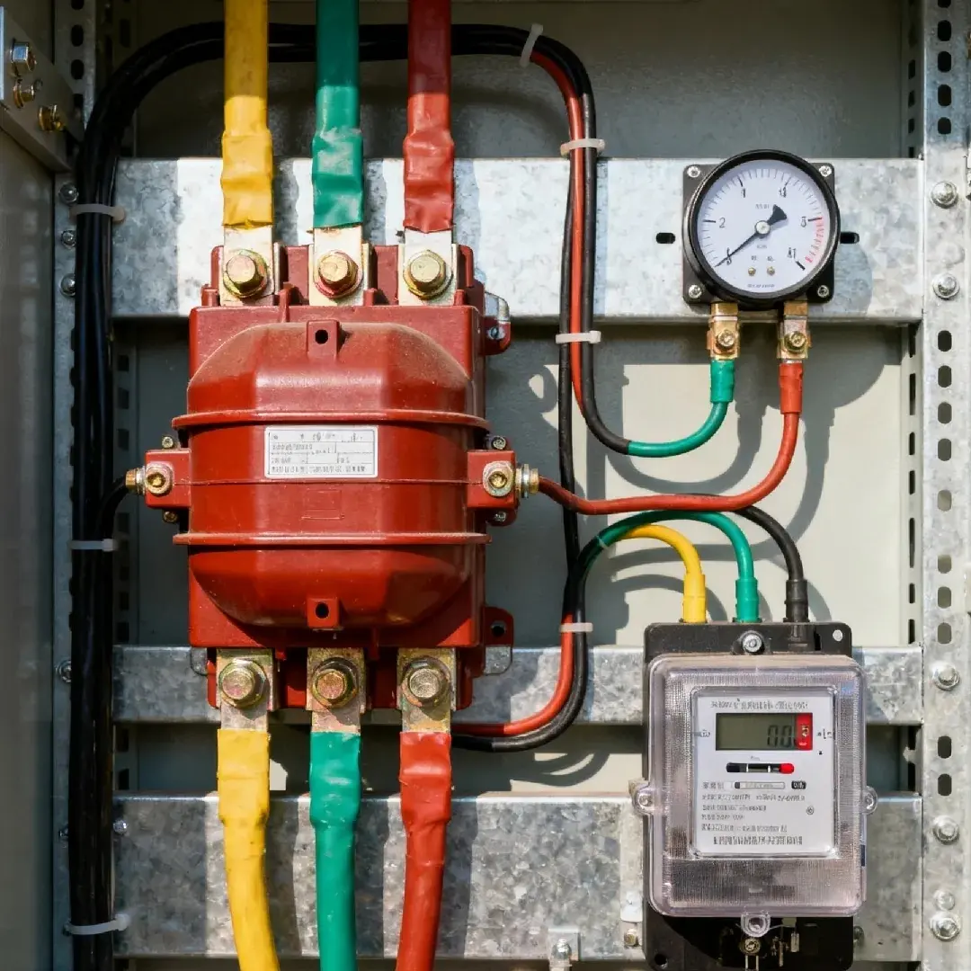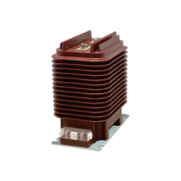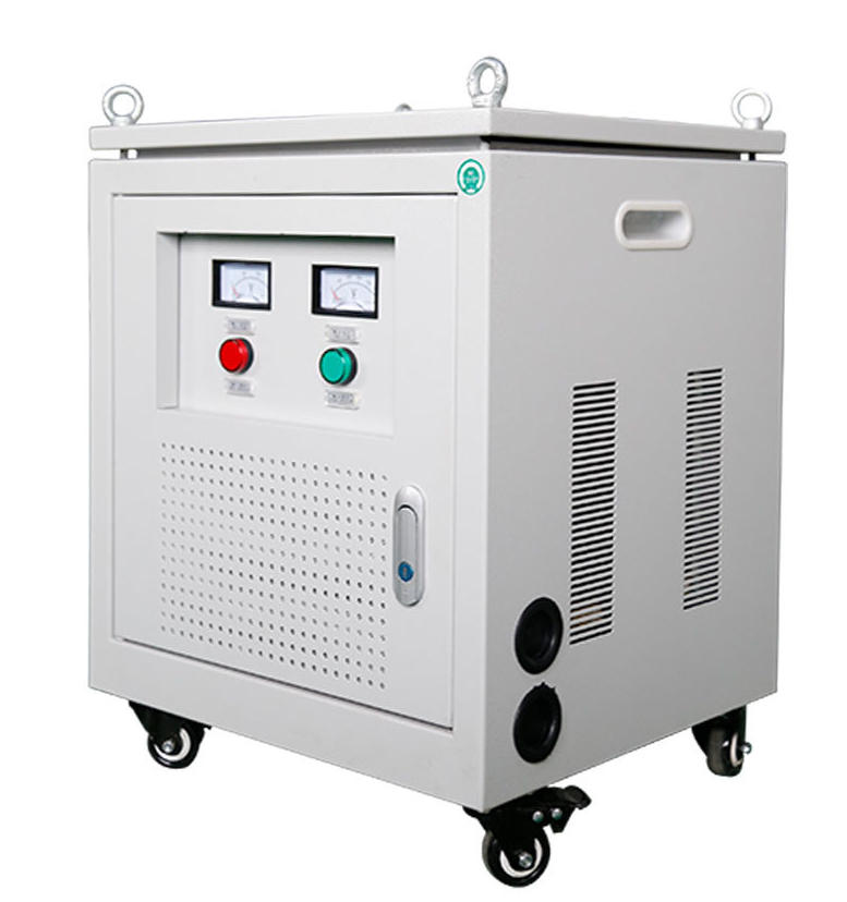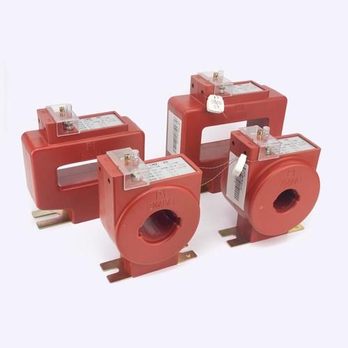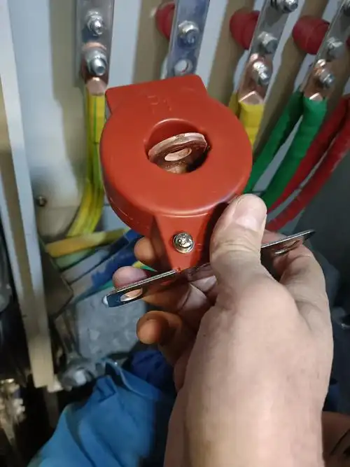
The CT “High Voltage” Myth Starts With a Missing Condition
A surprisingly common misconception in power systems is this: because a current transformer can generate very high voltage on its secondary, it must therefore be a kind of step-up transformer.
That conclusion is wrong. A current transformer does not increase voltage in normal operation. The dangerous high voltage appears only under one abnormal condition: when the CT secondary is open-circuited while primary current is still flowing.
This missing condition is the source of the confusion. In day-to-day service, a CT secondary is connected to a meter, relay, transducer, or protection input with very low impedance, so the secondary voltage stays low.
The Real Problem: Why People Think a Current Transformer Increases Voltage
Most electricians, technicians, and junior engineers first hear a safety rule before they hear the theory: “Never open-circuit a CT secondary.” That rule is absolutely correct, but when it is taught without explanation, people naturally assume the CT must normally behave like a voltage step-up device.
It does not. The real situation is more precise:
Normal condition: CT secondary connected to a low-impedance burden, low secondary voltage.
Abnormal condition: CT secondary open, no current path, dangerously high induced voltage.
This is the key to understanding current transformer voltage behavior. The CT is not designed to boost voltage. It is designed to reproduce current proportionally.
Current Transformer Operating Principle: A CT Is Designed to Transform Current, Not Voltage
At its core, a current transformer is still a transformer. It has a magnetic core, a primary path, and a secondary winding. But its application and operating mode are very different from those of a general-purpose power transformer.
A CT is best understood as a current-source type transformer. Its purpose is to convert a large primary current into a smaller, standardized secondary current such as 5 A or 1 A.
That is why the phrase why current transformers do not increase voltage has a simple answer: because voltage transformation is not the CT’s operating target. Current reproduction is.
Primary and Secondary Winding Structure in a Current Transformer
In many practical CT designs, the primary winding is just one turn. Often it is not even a wound coil in the usual sense. It may simply be a busbar or cable passing through the CT core window.
The secondary winding, by contrast, has many turns. This large turns difference often misleads people into thinking the device should step up voltage like a conventional transformer. But that overlooks how the CT is loaded and controlled in practice.
The winding structure supports current scaling, not free voltage generation under load.
Ideal Ampere-Turn Balance: Why CT Secondary Current Is Stepped Down
The basic ideal relation is:
I1N1 = I2N2
From that, the secondary current is:
I2 = I1 × N1 / N2
Because the primary usually has very few turns and the secondary has many turns, the CT converts a high primary current into a lower, standardized secondary current.
Example:
Primary current: 400 A
CT ratio: 400/5 A
Secondary current at rated primary current: 5 A
That is the essence of transformer turns ratio and current step-down. The CT is fundamentally a current step-down device.
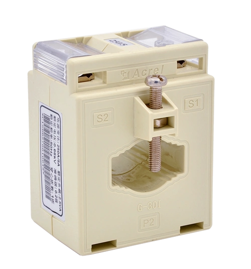
Why a Current Transformer Does Not Increase Voltage in Normal Operation
Now we get to the point that matters most in the field. A CT secondary in normal service is connected to a measuring or protection burden that has very low impedance.
Since the CT is trying to drive a defined current, the actual secondary voltage depends on the burden impedance. The relation is straightforward:
U2 = I2 × Z
If the burden impedance is low, then the secondary voltage must also be low. That is why the CT does not “step up voltage” in ordinary operation.
Secondary Burden Keeps CT Voltage Low
The burden may be an ammeter, energy meter, relay input, test block wiring, or a combination of these. In properly designed installations, the total burden is intentionally kept within the CT’s rated VA and accuracy class.
In practical terms, that means the secondary voltage is often just a few volts. Even in larger systems, it may only rise into the low tens of volts under rated burden.
That is normal and expected.
Near-Short-Circuit Operation Is Normal for CTs
This is one of the most important ideas in CT theory: a current transformer secondary is meant to operate in a condition that is electrically close to a short circuit.
That phrase sometimes surprises people, but it is exactly right. Compared with a voltage transformer, the CT secondary circuit has very low impedance, so the induced voltage needed to push rated current is small.
In other words, the connected meter or relay effectively “holds” the secondary voltage down by providing a current path.
Why an Open-Circuit CT Secondary Produces Dangerous High Voltage
The danger begins the instant that low-impedance current path is broken while primary current still exists. Then the CT is forced into a completely different operating condition.
This is where the famous warning comes from, and it is fully justified.
What Happens to Magnetic Flux When CT Secondary Is Open
When the secondary is open, the secondary current becomes:
I2 = 0
That destroys the usual ampere-turn balance. The primary ampere-turns are no longer opposed by secondary ampere-turns, so the primary magnetomotive force is used almost entirely to magnetize the core.
The result is a sharp rise in magnetic flux. In real CTs, the core quickly moves toward saturation, and flux waveform distortion becomes severe.
This condition also causes heating, waveform stress, insulation stress, and significant safety risk to anyone near the open terminals.
Faraday’s Law Explains the Voltage Spike
The voltage induced in the secondary follows Faraday’s law:
U = N × dΦ/dt
Because the CT secondary has many turns, even a rapidly changing flux can create a very large terminal voltage.
That is why open-circuit CT secondary voltage can reach hundreds, thousands, or in some cases more than 10 kV, depending on:
Primary current magnitude
CT ratio
Core material and saturation characteristics
Frequency
Secondary turns count
Waveform distortion during the event
So the correct statement is not “a CT steps up voltage.” The correct statement is: an open-circuited CT secondary can develop dangerously high induced voltage because the normal current balance is lost.
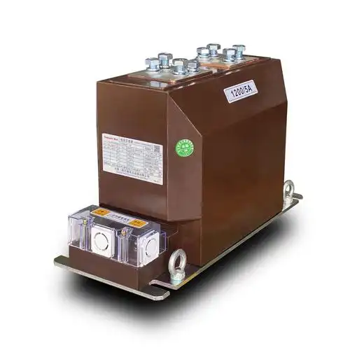
Current Transformer vs Voltage Transformer: The Key Difference
The easiest way to remove the misconception is to compare a CT with a PT or VT.
This is the real difference between a current transformer and a voltage transformer:
Current Transformer (CT): designed to reproduce current; the secondary works into low impedance.
Potential Transformer / Voltage Transformer (PT/VT): designed to reproduce voltage; the secondary works into comparatively high impedance.
A PT has primary voltage imposed by the system. Its secondary voltage follows the turns ratio. A CT has primary current imposed by the system. Its secondary current follows the turns ratio.
Current Transformer Voltage Behavior vs Voltage Transformer Behavior
For a PT/VT, voltage transformation is the main design function. For a CT, current transformation is the main design function.
That distinction matters because many people unconsciously apply ordinary power-transformer intuition to CTs. That intuition fails here.
So when discussing current transformer voltage behavior, always ask: Is the secondary loaded normally, or is it open? Without that condition, the statement is incomplete.
Real-World CT Data: Typical Secondary Current, Burden, and Voltage
In actual switchgear, motor control centers, generator panels, substations, and energy metering cabinets, CT secondary voltage under normal conditions is usually modest.
The burden rating tells the story. A 5 VA burden at 5 A corresponds to only 0.2 ohms of impedance. That means just 1 volt at rated current.
Here is the practical data engineers use when selecting or checking CT circuits.
Table: Typical CT Secondary Conditions in Normal Service
| CT Ratio | Secondary Rating | Typical Burden (VA) | Approx. Burden Impedance | Approx. Secondary Voltage |
|---|---|---|---|---|
| 100/5 A | 5 A | 2.5 VA | 0.1 Ω | 0.5 V |
| 200/5 A | 5 A | 5 VA | 0.2 Ω | 1.0 V |
| 400/5 A | 5 A | 10 VA | 0.4 Ω | 2.0 V |
| 1000/1 A | 1 A | 5 VA | 5 Ω | 5.0 V |
| 2000/1 A | 1 A | 10 VA | 10 Ω | 10.0 V |
These values are not theoretical curiosities. They align with what technicians measure in real systems using proper test methods. Under rated burden, the secondary voltage is low because the burden is low.
This is the strongest practical answer to why current transformers do not increase voltage under normal service.
Proof by Example: Why CTs Stay Low-Voltage Under Load
Take a common metering CT: 400/5 A, 10 VA.
At rated secondary current, the allowable burden impedance is:
Z = VA / I² = 10 / 25 = 0.4 Ω
So the rated secondary voltage is:
U2 = I × Z = 5 × 0.4 = 2 V
That means when the primary carries 400 A and the CT is correctly connected to its burden, the secondary voltage is only about 2 volts.
Even if the actual burden is slightly higher because of lead length or extra relay inputs, the voltage is still nowhere near “step-up transformer” territory.
Field engineers see this all the time in motor feeders, incomers, and distribution boards. A healthy loaded CT is a low-voltage device on the secondary side.
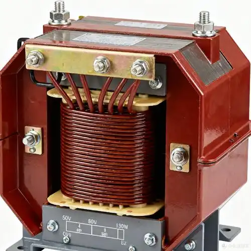
Dangerous Case: Open-Circuit Secondary Voltage in Practice
Now compare that 2 V normal condition to an accidental open-circuit event. Suppose a test link is withdrawn, a terminal loosens, a meter is removed incorrectly, or a maintenance worker disconnects a lead before shorting the CT secondary.
The CT can no longer push its designed secondary current into a proper burden. The core flux rises sharply, and the induced voltage can climb to a dangerous level almost instantly.
In the field, reported open-circuit secondary voltages vary widely. Smaller metering CTs may produce hundreds of volts. Larger protection-class CTs under substantial primary current may produce several kilovolts. In severe cases, especially with high turns counts and strong excitation, values above 10 kV are possible.
These are not abstract textbook warnings. Open-circuit CT incidents have caused:
Insulation breakdown
Terminal flashover
Meter and relay input damage
Severe electric shock risk
Core overheating and permanent accuracy degradation
Table: Normal Operation vs Open-Circuit CT Secondary Behavior
| Condition | Secondary Current | Burden Impedance | Core Flux | Secondary Voltage | Safety Risk |
|---|---|---|---|---|---|
| Normal metering load connected | Rated 1 A or 5 A | Low | Low | Low | Low |
| Relay/meter circuit connected | Near rated | Low | Controlled | Low to moderate | Low |
| Secondary accidentally open | 0 A | Extremely high | Very high/saturated | Very high | Severe |
| Maintenance without shorting secondary | 0 A | Open circuit | Very high/saturated | Potentially lethal | Extreme |
Common Installation and Safety Rules for Current Transformers
If there is one CT rule that should never be treated casually, it is this: never leave the secondary open while the primary is energized.
That rule exists because the hazard is real, immediate, and well documented across utility, industrial, and commercial power systems.
Good practice includes:
Short the CT secondary before disconnecting meters or relays.
Use shorting terminal blocks or test switches designed for CT circuits.
Verify polarity and terminal identification clearly.
Keep burden within the CT’s rated VA and accuracy limit.
Inspect wiring tightness during commissioning and maintenance.
Train personnel never to “just lift one wire” on a live CT circuit.
In many plants, the most dangerous CT incidents do not come from design errors. They come from rushed maintenance, undocumented field modifications, or misunderstanding of how a CT differs from a normal transformer.
That is why product quality and terminal design matter. Manufacturers such as Weisho Electric are often evaluated not only on ratio and accuracy, but also on insulation reliability, terminal robustness, and suitability for real switchgear conditions where safe handling is essential.
Featured Snippet Summary: Why Doesn’t a Current Transformer Step Up Voltage?
A current transformer does not step up voltage in normal operation because its secondary is connected to a low-impedance burden and is designed to reproduce current, not generate high voltage. The secondary voltage stays low because U = I × Z and the burden impedance is intentionally small. Dangerous high voltage appears only when the secondary is open-circuited while primary current still flows.
Deeper Technical Perspective: Why the Misconception Persists Even Among Skilled People
Even experienced technicians can stumble here because the CT contains a real transformer core and real turns ratio. On paper, it feels natural to think many secondary turns should mean higher voltage.
But transformer behavior is never determined by turns ratio alone. It is determined by turns ratio plus source condition plus load condition.
In a CT:
The primary current is dictated by the power circuit.
The secondary is intended to carry proportional current.
The load impedance is deliberately low.
That operating combination is what keeps voltage low in normal service.
The moment the burden disappears, the operating mode changes completely. This abrupt change is what creates the impression that the CT “suddenly becomes” a high-voltage device. In reality, it has simply lost its intended secondary current path.
Practical Field Example From Industrial Distribution
Consider a 13.8 kV industrial feeder with a 600/5 A metering CT connected to a digital power meter and a protection relay. The combined burden, including lead resistance, might be around 0.25 Ω.
At rated secondary current of 5 A, the secondary voltage is only:
U = 5 × 0.25 = 1.25 V
That is entirely normal. No voltage step-up issue exists at all.
Now imagine the meter is replaced during a shutdown that is assumed safe, but the feeder is still carrying residual or transferred load current. A secondary lead is opened without first applying the shorting link. The current path disappears. The CT is no longer operating in its designed condition.
What follows may be a loud snap at the terminals, unexpected arcing, damage to the meter circuit, or a dangerous touch potential. This is why seasoned relay technicians are strict about CT isolation procedures.
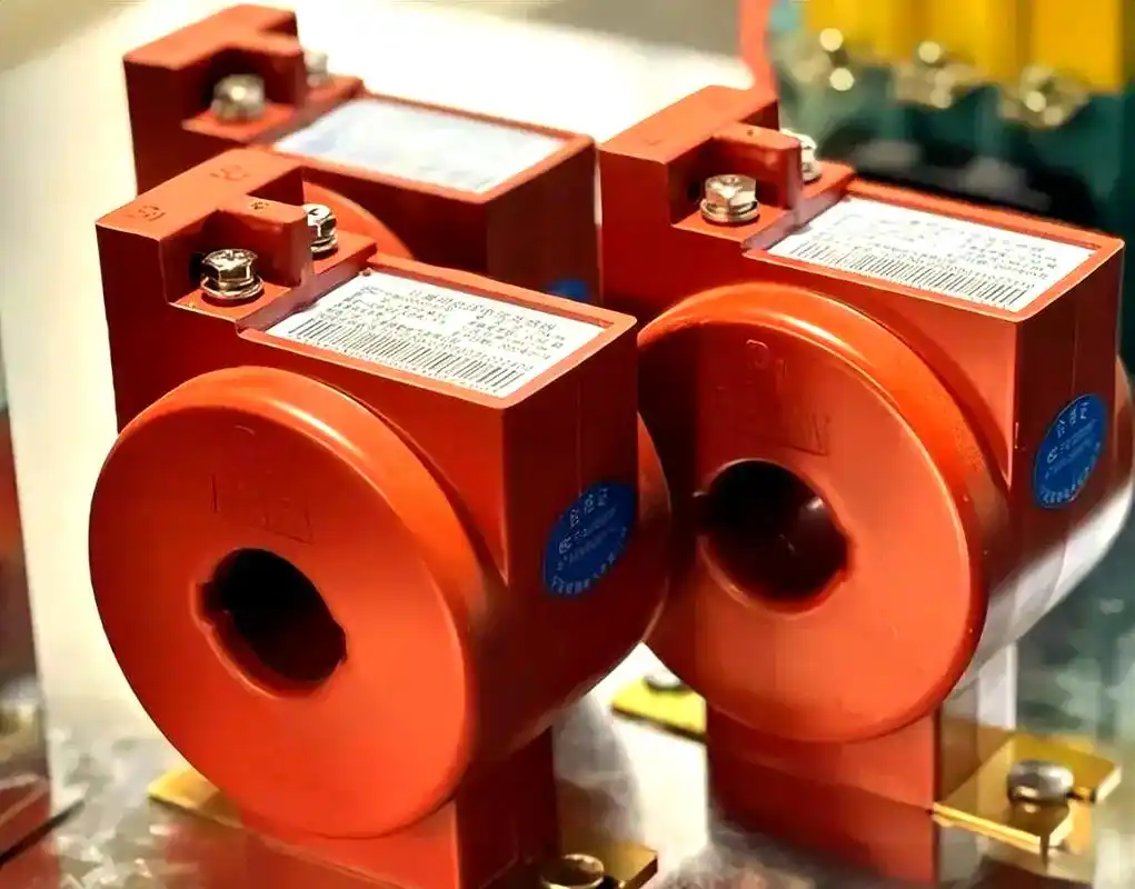
Why CT Burden Rating Is More Important Than Many People Realize
Burden is not just an accuracy specification buried in a datasheet. It directly affects both measurement quality and secondary voltage level.
If burden increases, secondary voltage must increase to maintain secondary current. Within rated limits, that is fine. Beyond rated limits, ratio error and phase error grow, especially for metering-class CTs.
So when engineers review current transformer operating principle, they should never separate it from burden analysis. The CT, the wiring, and the connected device form one system.
Typical burden contributors include:
Input impedance of the meter or relay
Lead length from CT to panel
Terminal block contact resistance
Test switch resistance
Any series auxiliary device in the current loop
This is also why 1 A CT secondaries are often preferred for long cable runs: lower current means lower lead loss for a given loop, which can simplify burden management.
What Engineers and Technicians Should Remember Most
If you remember only three things, remember these:
1. A CT is a current transformer, not a voltage transformer.
2. Its secondary voltage is low in normal operation because the burden impedance is low.
3. High voltage appears only when the secondary circuit is opened under primary current.
That is the clearest answer to why current transformers do not increase voltage.
FAQ
Why doesn’t a current transformer step up voltage like a regular transformer?
A current transformer is designed to step down current into a low-impedance secondary circuit. Because the burden impedance is small, the secondary voltage remains low during normal operation. It is not intended to function as a voltage step-up transformer.
Why does a CT produce high voltage when the secondary is open?
When the secondary is open, no secondary current flows to balance the primary ampere-turns. Core flux rises sharply, and the many secondary turns can then induce a dangerously high voltage according to Faraday’s law.
Is a current transformer a step-up transformer or a step-down transformer?
It is primarily a current step-down device. Its main job is to convert large primary current into standardized secondary current such as 5 A or 1 A, not to step up voltage.
What is the difference between a current transformer and a voltage transformer?
A current transformer reproduces current and operates with a low-impedance secondary burden. A voltage transformer, also called a PT or VT, reproduces voltage and normally operates with a comparatively high-impedance secondary load.
What voltage does a CT secondary normally have?
Under rated burden, the CT secondary commonly has only a few volts. Depending on burden, ratio, and whether the secondary is rated at 1 A or 5 A, it may range from below 1 V to the low tens of volts.
Can an open-circuit current transformer be dangerous?
Yes. It is extremely dangerous. An open-circuit CT secondary can develop voltage high enough to damage insulation, flash over terminals, harm connected devices, and seriously injure personnel.
Why is CT secondary burden important?
Burden affects both accuracy and secondary voltage. If burden is too high, the CT may develop more voltage than intended, increasing ratio error and phase error. Keeping the burden within rated limits is essential for safe and accurate operation.
Prevent CT Open-Circuit Hazards in Real Installations
Before energizing, modifying, or servicing any CT circuit, review the burden, wiring path, terminal blocks, test switches, and shorting procedure in detail. Do not rely on assumptions, old drawings, or memory.
Audit every current transformer secondary circuit now. Confirm the burden is within rating, verify that shorting links are in place where required, inspect all terminations, and train maintenance staff on live CT hazards. If your installation depends on accurate and safe current measurement, treat CT secondary handling as a critical safety discipline, not a routine wiring task.