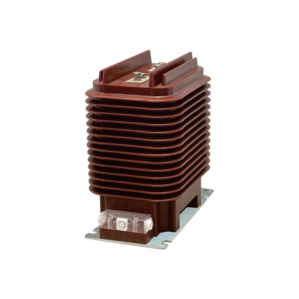
One-Sentence Difference Between Class P and Class TP
Class P current transformers are steady-state protection CTs evaluated mainly on AC fault current accuracy, while Class TP current transformers are transient protection CTs designed to remain reliable during the first moments of a fault when DC offset is present.
This is the core answer behind search queries like current transformer protection class P explained, what is class TP in current transformers, and difference between class P and class TP CTs.
Why CT Protection Class Selection Matters
Choosing the wrong CT class can directly affect relay operation.
When a fault starts, the current waveform is often asymmetrical and includes a decaying DC component. If the CT core saturates too early, the relay may see a distorted secondary current and either trip late, fail to trip, or trip incorrectly.
In ordinary feeder protection, this risk may be acceptable with Class P.
In busbar differential, line differential, or auto-reclosing applications, it is often not acceptable at all.
What Is Class P in Current Transformers?
Class P means Protection class under IEC practice for protective current transformers.
It is assessed by steady-state composite error under AC fault current conditions. In simple terms, the class checks performance at high multiples of rated current, but it does not fully evaluate the short-circuit transient with DC offset.
This is why Class P is widely used for conventional CT accuracy classes for protection relays in medium-voltage and many high-voltage applications where transient duty is not severe.
How to Read 5P10, 5P20, and 10P20
The marking combines an allowable composite error and an accuracy limit factor.
5P20 means the CT composite error does not exceed 5% at 20 times rated primary current. 10P20 means up to 10% composite error at the same current multiple.
Common interpretations are straightforward:
5P10: composite error ≤ 5% at 10 × rated primary current
5P20: composite error ≤ 5% at 20 × rated primary current
10P20: composite error ≤ 10% at 20 × rated primary current
For example, a 1000/1 A CT marked 5P20 is expected to remain within its protection error limit up to a primary current of about 20,000 A, assuming the specified burden conditions are met.
Core Characteristics of Class P CTs
Class P CTs typically use a core without an intentional air gap.
That makes them economical and compact, but it also makes them more vulnerable to saturation when fault current contains a strong DC component.
In practical engineering terms, a P-class CT can look acceptable on paper under symmetrical RMS fault duty, yet still distort badly during the first few cycles of an asymmetrical short circuit.
Typical Applications of Class P CTs
Class P is commonly used where the protection objective is solid but not highly sensitive to transient CT behavior.
10 kV switchgear overcurrent protection
35 kV feeder instantaneous overcurrent protection
General short-circuit protection in industrial distribution
Many 110 kV conventional protection schemes without demanding differential or reclosing requirements
In many standard switchboards, 5P10 or 5P20 is the default protective CT choice because it balances cost, size, and performance well.
What Is Class TP in Current Transformers?
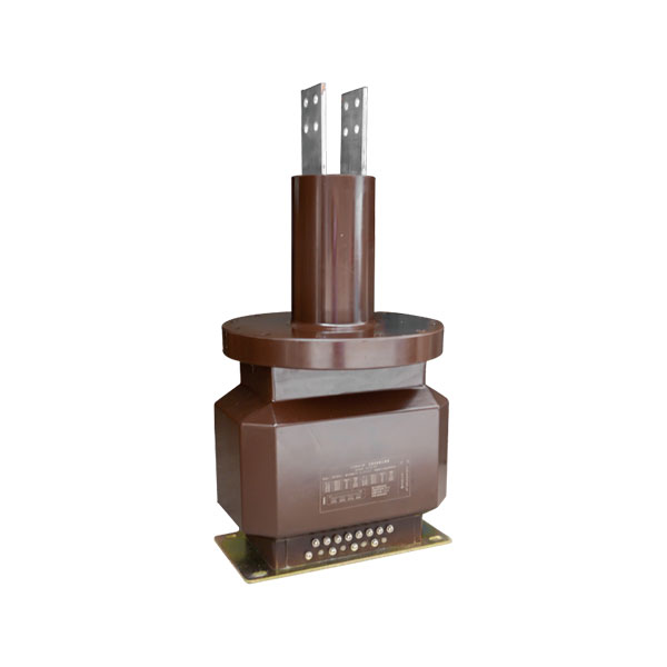
Class TP means Transient Protection.
These CTs are engineered to preserve useful accuracy during the initial fault period, including the effect of the decaying DC offset that often appears in short-circuit current.
If you are asking what class TP is in current transformers, the practical answer is simple: it is the CT class used when early-fault waveform fidelity matters to relay security and speed.
Why Transient Performance Matters
Most real fault currents are not perfectly symmetrical at inception.
Depending on the point-on-wave when the fault starts and on the X/R ratio of the system, the first cycles can contain a large DC component that shifts the flux in the CT core sharply in one direction.
In high-X/R transmission systems, the DC offset can decay slowly. That means a CT may saturate almost immediately if it was selected only for steady-state AC accuracy.
This is one of the most important protective current transformer saturation characteristics engineers must consider.
Main Features of Class TP CTs
Class TP CTs generally have larger core cross-sections than Class P CTs.
Some TP subclasses use a small or large air gap to control remanent flux and improve transient recovery after fault clearing.
Larger magnetic core area
Better tolerance to DC-offset fault duty
Lower remanence in certain subclasses
Improved suitability for differential and reclosing schemes
Higher cost and larger physical size
That higher cost is not arbitrary. It reflects tighter magnetic design, more demanding test performance, and often stricter manufacturing control.
Typical Applications of Class TP CTs
Class TP is most often specified where a relay must make fast and correct decisions during the first fault cycles.
220 kV line differential protection
330 kV and 500 kV busbar differential protection
EHV and UHV substations with auto-reclosing
Long transmission line differential schemes
Critical transformer differential applications where CT saturation risk must be tightly controlled
In these networks, the cost of a misoperating relay can be far greater than the extra cost of a TP-class CT.
Types of Class TP CTs: TPS vs TPX vs TPY vs TPZ
IEC transient protection subclasses divide TP performance into several categories.
Each one addresses transient accuracy, remanence behavior, and application duty differently.
TPS Current Transformer Class
TPS CTs are usually specified by excitation characteristics, secondary winding resistance, and turns ratio error.
They are often selected for high-performance differential schemes, especially busbar protection, where relay manufacturers may require a specific excitation curve rather than a simple class marking.
TPS has no remanence limit requirement in the class definition.
That does not make it inferior by default. It simply means the application must be checked against the full CT and relay design requirements.
TPX Current Transformer Class
TPX CTs use a core without an air gap.
They are assessed on transient peak instantaneous error, but remanence is not limited.
Because residual magnetism can remain significant after a fault, TPX is generally less attractive for systems with frequent or critical auto-reclosing duty.
TPY Current Transformer Class
TPY CTs include a small air gap in the core design.
This limits remanence to about 10% of saturation flux, which is a major practical advantage in applications with repeated fault events or fast reclosing.
Among engineers comparing CT accuracy classes for protection relays, TPY is often the preferred choice for high-voltage line differential protection because it combines strong transient behavior with controlled residual flux.
TPZ Current Transformer Class
TPZ CTs usually use a larger air gap and therefore have very low remanence.
However, the performance concept differs from TPX and TPY because the evaluation emphasizes AC component error rather than direct DC component accuracy.
TPZ can be valuable in specialized applications, but engineers must confirm compatibility with the intended relay algorithm and system transient conditions.
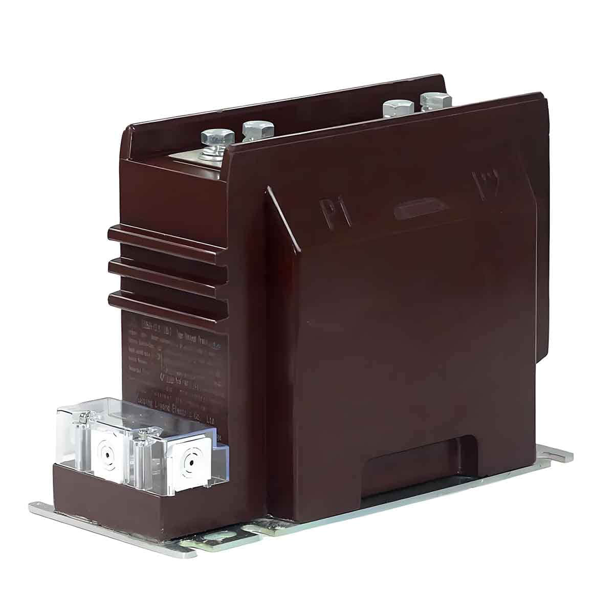
Class P vs Class TP CTs: Key Differences
The central difference between class P and class TP CTs is not marketing terminology. It is the difference between steady-state fault accuracy and transient fault fidelity.
If the relay only needs dependable performance under conventional AC fault assumptions, Class P may be enough. If the relay must remain stable and fast during the first asymmetrical fault cycles, Class TP is often the right answer.
Class P vs Class TP Current Transformers
| Parameter | Class P | Class TP |
|---|---|---|
| Full meaning | Protection | Transient Protection |
| Main evaluation basis | Steady-state composite error | Transient performance during DC-offset faults |
| Fault current considered | AC RMS component | Full transient waveform including DC offset |
| Core design | Usually no air gap | May include air gap to reduce remanence |
| Saturation tendency | Higher under transient faults | Lower during early fault period |
| Common markings | 5P10, 5P20, 10P20 | TPS, TPX, TPY, TPZ |
| Typical use | MV/HV conventional protection | EHV differential, busbar, reclosing systems |
| Relative cost | Lower | Higher |
Protective Current Transformer Saturation Characteristics Explained
CT saturation is the bridge between theory and relay behavior.
A relay does not respond to the primary fault current directly. It responds to the CT secondary current, so once the CT saturates, the relay's input signal can become severely distorted.
How DC Offset Causes CT Saturation
An asymmetrical short circuit contains an AC component plus a decaying DC component.
The DC component pushes the magnetic flux in one direction, which can move the core above the knee-point region faster than AC current alone would do.
In transmission networks with high X/R ratios, the DC offset can be substantial. Field studies and utility practice commonly show that the first-cycle asymmetrical peak can approach nearly double the symmetrical peak under worst switching angles.
This is why a CT that passes steady-state testing may still saturate in the first few milliseconds of a real fault.
Why Remanence Matters After Fault Clearing
After a heavy fault is interrupted, some magnetic flux may remain in the CT core. This is called remanence or residual magnetism.
If another event occurs shortly afterward, especially during auto-reclosing, the CT starts from a biased magnetic state instead of zero. That makes it easier to saturate again.
In practical substation design, this is a major reason why remanence control is not a theoretical detail but a relay performance issue.
Why TPY Is Often Preferred in Reclosing Systems
TPY limits remanence to 10% of saturation flux.
That means the CT has a better chance of reproducing the next fault current correctly after a trip-and-reclose sequence.
For line differential protection on EHV lines with single-pole or three-pole auto-reclosing, TPY is often selected because it improves both security and dependability.
Real-World Examples of Class P and Class TP Selection
Engineering selection should always match the system voltage, protection function, fault level, X/R ratio, burden, and relay type.
The examples below reflect common utility and industrial practice.
Example 1: 10 kV Switchgear Overcurrent Protection
A typical industrial 10 kV switchgear lineup may use feeder overcurrent and earth-fault protection with no differential function and no special reclosing duty.
In this case, a 5P20 CT is often fully adequate because the relay mainly requires reliable steady-state fault current reproduction within the specified burden.
Real-world practice: many metal-clad MV switchboards use protection CTs such as 300/1 A, 600/1 A, or 1000/1 A in 5P10 or 5P20 for feeder protection.
Example 2: 35 kV Feeder With Instantaneous Protection
Consider a 35 kV feeder using instantaneous overcurrent plus time-overcurrent elements, but without line differential and without demanding auto-reclosing performance.
Here, 5P20 or 10P20 is still commonly acceptable, provided fault duty, relay burden, and lead resistance are correctly checked.
The key point is that increasing from 5P10 to 5P20 improves the steady-state limit factor, but it does not automatically convert the CT into a transient-duty solution.
Example 3: 220 kV Line Differential Protection With Auto-Reclosing
A 220 kV transmission line often has a high system X/R ratio and a protection philosophy that demands very fast line differential operation.
If auto-reclosing is also required, remanence becomes critical after fault clearing.
In this case, TPY is frequently preferred because it combines transient accuracy with remanence control.
Real-world utility specifications commonly call for TPY on 220 kV line bays where fast high-speed protection and reclosing reliability are both essential.
Example 4: 500 kV Busbar Protection
Busbar differential protection at 500 kV is one of the most demanding CT applications in the substation.
Close-in external faults can produce severe asymmetrical currents, and CT mismatch or saturation can threaten security.
For this reason, utilities often specify TPS or TPY based on the relay manufacturer's exact requirements, excitation curve needs, and remanence limits.
In large EHV substations, this is not a cost-driven decision. It is a system stability decision.
When to Use Class P vs Class TP
| System / Protection Scenario | Recommended CT Class | Reason |
|---|---|---|
| 10 kV switchgear overcurrent protection | 5P10 or 5P20 | Cost-effective and adequate for steady-state fault accuracy |
| 35 kV feeder instantaneous overcurrent | 5P20 or 10P20 | Suitable where transient DC accuracy is not a key requirement |
| 110 kV conventional protection | Class P in many cases | Common choice if no demanding differential or reclosing duty exists |
| 220 kV line differential with reclosing | TPY | Better transient response and controlled remanence |
| 330 kV/500 kV bus differential | TPS or TPY | Higher stability and accuracy during severe transient faults |
| Long transmission line differential | TPY | Improved performance with large DC offset during close-in faults |
How to Choose the Right CT Accuracy Class for Protection Relays
CT selection should never be based on voltage alone.
It should be based on the protection function, fault waveform severity, relay algorithm, system X/R ratio, burden, lead resistance, and any reclosing duty.
Choose Class P for Standard Protection Schemes
Use Class P where the application is conventional and where the relay does not depend on high-fidelity reproduction of the earliest fault transient.
Overcurrent protection
Instantaneous short-circuit protection
Typical industrial and utility feeder protection
Low- and medium-voltage systems
For many such schemes, Class P remains the most economical and technically appropriate choice.
Choose Class TP for Differential and High-Speed Critical Protection
Use Class TP when CT saturation during early fault conditions could compromise relay stability or speed.
Busbar differential protection
Line differential protection
Critical transformer differential schemes
EHV and UHV protection systems
This is especially important where external fault stability is critical and where false differential current due to CT saturation cannot be tolerated.
Check Reclosing Duty and Remanence Limits
If the scheme includes auto-reclosing, do not ignore remanence.
Even when a steady-state calculation looks acceptable, residual flux after the first fault can impair the next operation. In these cases, TPY often deserves priority because of its controlled remanence behavior.
Common Mistakes When Comparing Class P and Class TP CTs
Many CT specification errors happen because engineers compare ratio and burden correctly, but compare transient duty incorrectly.
Mistake 1: Assuming Higher P-Class Rating Solves Transient Problems
A 5P20 CT is not automatically suitable for transient-heavy duty just because it has a higher accuracy limit factor than a 5P10 CT.
It remains a Class P device evaluated for steady-state AC fault accuracy, not a transient protection CT designed for DC-offset waveform fidelity.
Mistake 2: Ignoring Remanence in Auto-Reclosing Systems
Residual magnetism can be the hidden reason a protection scheme behaves inconsistently across repeated operations.
This is particularly important in line protection where a second fault or unsuccessful reclose may occur before the CT fully resets magnetically.
Mistake 3: Selecting by Cost Alone
Class P CTs are cheaper, smaller, and widely available.
But if the application is a bus differential or EHV line differential scheme, the lower purchase price can be wiped out instantly by nuisance trips, failure to trip, commissioning delays, or relay redesign.
FAQ
What does 5P20 mean in a current transformer?
It means a protection CT whose composite error does not exceed 5% at 20 times rated primary current, under the specified burden and test conditions.
What is Class TP in current transformers?
Class TP refers to transient protection CTs designed to remain accurate during the initial fault interval when the current includes a DC offset component.
What is the difference between Class P and Class TP CTs?
Class P is tested mainly for steady-state AC fault accuracy, while Class TP is designed and evaluated for transient fault performance, including DC-offset conditions.
Is Class P enough for differential protection?
In some limited cases, it may be used, but in many HV and EHV differential applications, it is insufficient because transient saturation can cause maloperation or loss of stability.
Which TP class is best for auto-reclosing applications?
TPY is often preferred because its remanence is limited to 10% of saturation flux, making it better suited for repeated operations and reclosing duty.
Why are TP-class CTs more expensive?
They usually need larger cores, stricter transient performance control, tighter manufacturing tolerances, and in some designs an air-gap structure to limit remanence.
Final Takeaway and Expert Help
The practical rule is simple.
Class P fits most conventional overcurrent and short-circuit protection in low-, medium-, and some high-voltage systems. Class TP is the safer and often necessary choice for transient-heavy, high-voltage, differential, busbar, and reclosing applications.
If you need current transformer protection class P explained, the answer is steady-state protection accuracy.
If you need to know what class TP is in current transformers, the answer is transient performance under DC-offset fault conditions.
And if you are comparing the difference between class P and class TP CTs, the deciding factor is usually not nominal ratio or burden alone, but whether the protection scheme can tolerate early-fault CT saturation and remanence effects.
CTA
Need help selecting the right CT class for your protection scheme?
Contact our engineering team today for a project-specific review of CT class selection, relay compatibility, excitation requirements, burden calculations, differential scheme suitability, and reclosing duty assessment.
Send your single-line diagram, protection philosophy, voltage level, CT ratios, and relay model list now, and get an expert recommendation on whether Class P, TPS, TPX, TPY, or TPZ is the right choice for safe and dependable protection performance.