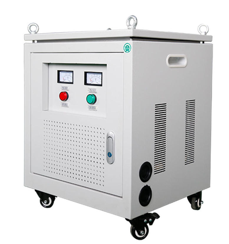
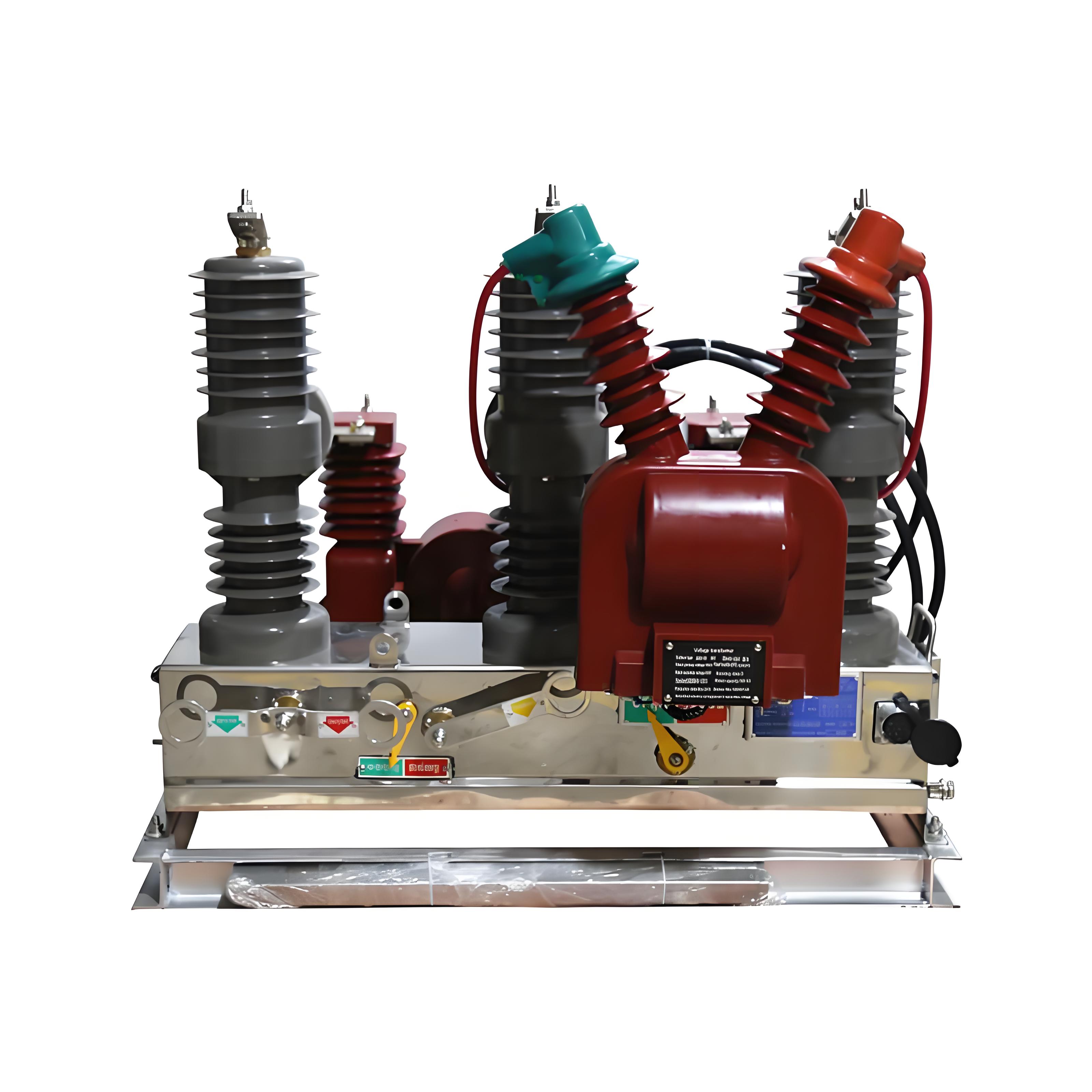
A zigzag transformer, also called a Zig-Zag transformer or Z-type transformer, is a specialized three-phase transformer built primarily to create an artificial neutral point in a system that does not naturally have one.
In practical power engineering, that means one thing above all else: it gives a delta-connected or otherwise ungrounded three-phase network a safe and controllable way to implement system grounding.
That is why engineers often refer to it as a neutral earthing transformer for three-phase systems. Its value is not mainly voltage conversion. Its value is grounding performance, fault management, and zero-sequence current control.
If you work with industrial distribution, renewable energy collection grids, generator grounding, or utility substations, understanding the zigzag transformer grounding applications is not optional. It is fundamental to protection design.
Zigzag Transformer Definition
A zigzag transformer is a special-purpose three-phase transformer whose windings are connected in a zigzag pattern so that the unit can create a neutral point for systems where no neutral exists.
Unlike a standard power transformer, its primary mission is usually not stepping voltage up or down. Instead, it is installed to provide a ground reference and an effective path for earth-fault current.
In many projects, a zigzag unit is paired with a neutral grounding resistor (NGR) or an arc suppression coil to precisely control how the system behaves during a line-to-ground fault.
Why Three-Phase Systems Need a Zigzag Grounding Transformer
Many three-phase networks operate in delta configuration at medium voltage. Delta systems are common in industrial plants, wind and solar collector systems, mining sites, motor-heavy process facilities, and some utility distribution arrangements.
The challenge is simple: delta systems do not inherently provide a neutral point. Without a neutral, the system cannot be grounded in the usual way.
That creates real protection problems.
Ground-fault detection becomes more difficult.
Transient overvoltages can become more severe.
Protection coordination may be unreliable.
Faulted equipment can remain energized longer than acceptable.
Insulation stress on healthy phases can increase during a single-line-to-ground fault.
In an ungrounded or poorly referenced system, the first ground fault may not produce enough current to trip quickly. That sounds harmless until it causes sustained arcing, insulation deterioration, or a second fault on another phase.
A second ground fault on a different phase can effectively turn into a phase-to-phase short circuit through ground. That is when damage escalates fast.
This is exactly where a zigzag grounding transformer earns its place. It creates the missing neutral, establishes a known grounding method, and gives protective relays a predictable fault-current path.
In the field, this matters a lot. A 13.8 kV delta industrial bus supplying large motors may run for years without obvious grounding trouble, then one insulation breakdown exposes the weakness of the system design. Installing a correctly sized zigzag grounding transformer with a coordinated NGR changes the behavior of that bus from uncertain to manageable.
How a Zigzag Transformer Works
The zigzag grounding transformer working principle is elegant and very different from ordinary transformer connections.
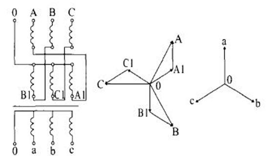
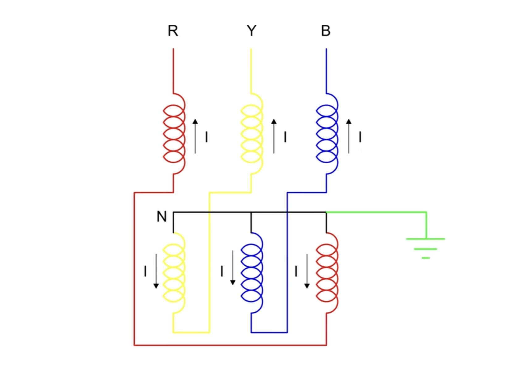
Each phase winding is split into two equal halves. These halves are wound with opposite polarity and cross-connected across different core legs.
The result is a winding arrangement that responds differently to balanced three-phase conditions and zero-sequence conditions.
Winding Configuration and Artificial Neutral Point
In a zigzag transformer, each phase is not confined to one core limb in the familiar sense of a simple wye winding. Instead, half of a phase winding is placed on one limb and the other half is placed on another limb.
These two halves have equal turns and opposite directions. Their tail ends are joined together to form a common point, and that common point is brought out as the neutral terminal.
That neutral is artificial, but electrically it performs the job engineers need: it becomes the point through which the system can be grounded.
This is the core reason the zigzag transformer is so widely selected as a grounding transformer on delta systems.
Zero Sequence Current Path in a Zigzag Transformer
The most important technical concept is the zero sequence current path in zigzag transformer operation.
During a single-line-to-ground fault, the three phase currents associated with the fault condition are zero-sequence in nature. A zigzag transformer offers a low zero-sequence impedance path so these currents can flow effectively to ground.
That low zero-sequence impedance is what makes the unit useful for grounding. Without it, fault current would be too limited or too unpredictable for reliable protective action.
In practical terms, the transformer allows ground-fault current to return through the neutral point, either directly or through a grounding element such as an NGR or Petersen coil.
This is why relay engineers can calculate expected earth-fault levels, choose pickup settings, and coordinate clearing times with confidence.
Balanced Operation Under Normal Conditions
Under balanced three-phase operation, the magnetomotive forces associated with positive- and negative-sequence components largely cancel inside the zigzag arrangement.
That means the neutral current remains very small in healthy operating conditions. The transformer stays relatively quiet from a system-current perspective until zero-sequence conditions appear.
That dual behavior is what makes the design so effective: stable in normal service, conductive during ground faults.
It is a clever answer to a very practical system problem.
Zigzag Transformer Working Principle for Grounding Applications
When engineers discuss the zigzag transformer working principle in grounding service, they are usually asking one question: how will the created neutral behave during a fault?
The answer depends on the grounding method selected.
The same zigzag transformer can support different grounding philosophies depending on the plant, utility code, arc-flash strategy, and fault-clearing objectives.
Direct Grounding of the Neutral
In some systems, the neutral point created by the zigzag transformer is solidly grounded. This means the neutral is connected directly to earth with no intentional impedance in between.
Solid grounding allows relatively high ground-fault current. The advantage is fast and decisive protective operation.
This method is common when the system is designed for immediate fault clearing and where equipment ratings and protection schemes can tolerate the resulting current.
However, solid grounding is not always preferred in medium-voltage industrial networks because fault energy can be high.
Neutral Grounding Resistor (NGR) Connection
One of the most common arrangements is a zigzag transformer with a neutral grounding resistor connected in series between the neutral and earth.
The NGR limits line-to-ground fault current to a predetermined level. That gives protection enough current to detect and isolate the fault, but avoids the destructive magnitude of a solidly grounded system.
Typical resistance-grounded MV systems may be designed for fault current values such as 50 A, 100 A, 200 A, 400 A, or 800 A, often for 10 seconds of short-time thermal duty. The right value depends on relay coordination, cable charging current, and plant operating philosophy.
For example, on a 13.8 kV system, an NGR selected for 400 A ground-fault current is not unusual in industrial distribution. On a 34.5 kV renewable collector system, the selected current may be lower or higher depending on feeder length, capacitance, and protection requirements.
Arc Suppression Coil Connection
The created neutral can also be grounded through an arc suppression coil, often called a Petersen coil.
This method is used in resonant grounding schemes to compensate for the system’s capacitive earth-fault current. It is especially useful in networks where intermittent arcing ground faults and overvoltage control are key concerns.
Instead of simply allowing or limiting fault current, the grounding system is tuned to reduce it significantly. That can help extinguish the arc in temporary single-phase ground faults.
In these applications, the zigzag transformer acts as the neutral-forming element, while the coil provides the resonant behavior.
Main Functions of a Zigzag Transformer
Although the artificial neutral point is the headline feature, a zigzag transformer offers several valuable system functions.
Creating an Artificial Neutral Point
This is the most common of all zigzag transformer grounding applications.
On a delta system, the transformer creates a neutral where none existed before. That neutral becomes the connection point for grounding hardware and protective devices.
Without this function, many delta systems would have to rely on less flexible or less compact grounding arrangements.
Harmonic Mitigation with a Zigzag Transformer
Harmonic mitigation with zigzag transformer design is another practical benefit. Zigzag transformers can suppress triplen harmonics, particularly the 3rd, 9th, and other multiples of 3.
These harmonic components are zero-sequence in nature. The zigzag connection gives them a path that helps prevent their propagation into the wider network.
This does not mean every zigzag transformer is a complete harmonic cure. Harmonic performance always depends on source characteristics, converter topology, grounding arrangement, and network impedance.
But in real installations, zigzag units often contribute meaningfully to improved power quality, especially where nonlinear loads or inverter-based resources are present.
Handling Unbalanced Loads
Zigzag transformers generally tolerate unbalanced loading better than many conventional connection types used for similar grounding purposes.
This is useful in plants where single-phase control loads, uneven feeder behavior, or asymmetrical fault conditions occur.
Engineers also value their robust behavior under abnormal system events, including lightning-related disturbances and switching transients.
Optional Auxiliary Secondary Supply
Some zigzag transformers include an additional secondary winding to provide station service power or auxiliary supply.
These units may use arrangements such as Znyn, allowing the transformer to perform both grounding duty and a limited supply function.
That can reduce equipment count in substations, renewable projects, and industrial yards where footprint and integration matter.
Zigzag Transformer vs Delta-Wye Transformer
This comparison is where many buyers get confused.
A standard delta-wye transformer is mainly chosen for voltage transformation, galvanic isolation, and supplying a wye-side neutral as part of a broader power-delivery function.
A zigzag transformer is mainly chosen for grounding and establishing a zero-sequence current path. It may not be intended to change voltage at all.
That difference is not academic. It affects specification, thermal design, price, protective behavior, and purchasing mistakes.
Delta-wye transformer: best when you need isolation and voltage conversion.
Zigzag transformer: best when you need a neutral point and controlled grounding on a three-phase system.
A delta-wye unit can sometimes be used in grounding-related roles, but it is usually larger, less purpose-optimized, and not always the most economical or elegant solution for pure grounding duty.
Zigzag Transformer Advantages and Disadvantages
No transformer type is perfect. Zigzag units offer major operational benefits, but they also come with design and cost tradeoffs.
Key Advantages
Creates an artificial neutral on systems that lack one.
Provides a low-impedance zero-sequence path for earth faults.
Works well with NGRs for resistance grounding.
Supports resonant grounding with arc suppression coils.
Helps suppress triplen harmonics and improve power quality.
Handles system imbalance well.
Can improve lightning and transient performance compared with less specialized arrangements.
Compact and purpose-built for grounding duty.
Main Disadvantages
The main drawback is that capacity utilization is about 0.866 compared with a standard transformer built from the same core material.
In plain language, that means material utilization is less efficient. As a result, the unit often costs more than a conventional delta-wye transformer of comparable grounding duty context.
Other disadvantages include:
Application-specific design, so generic selection is risky.
Not primarily intended for bulk power transfer.
Fault-duty thermal sizing must be done carefully.
Grounding resistor and relay coordination must be engineered together.
Experienced suppliers will explain this clearly rather than overselling the unit as a universal transformer solution.
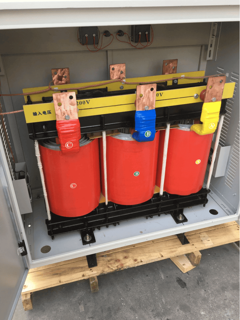
Zigzag Transformer Connection Diagram and Operating Example
It helps to visualize the connection in simple words.
Each line terminal connects into winding halves that are split and cross-connected onto different core limbs. The winding ends are then joined into a common neutral point. That neutral is routed either directly to earth or through an NGR or coil.
A simple operating scenario makes the behavior easier to understand.
Imagine a 15 kV delta industrial bus feeding large motors. Under normal balanced operation, the zigzag transformer carries very little neutral current.
Now suppose Phase A develops an insulation failure to ground through a damaged motor cable termination. The ground fault produces zero-sequence current. The zigzag transformer now provides the return path through its neutral.
If an NGR is installed and designed for 200 A for 10 seconds, the fault current is limited to roughly that value. Protective relays detect the event, alarm or trip according to design, and the transformer safely carries the fault duty until clearing.
That is the whole purpose of the device in one field example: controlled grounding, predictable fault current, coordinated protection.
Real-World Zigzag Transformer Applications
Zigzag transformers are not niche laboratory devices. They are used every day in power systems where grounding must be added intelligently.
Solar and Wind Power Collection Systems
Medium-voltage renewable energy collector systems often use inverter outputs and pad-mounted step-up arrangements that result in delta-based MV networks or systems where grounding design needs special care.
In utility-scale solar plants, 34.5 kV collector buses commonly require an engineered grounding solution. A zigzag grounding transformer with an NGR is a frequent choice.
Why? Because inverter-based resources can behave differently during faults than rotating machines. Protection settings need a stable reference and a known ground-fault path.
On wind farms, the same logic applies. Cable-rich collector systems also have capacitive charging current, so the grounding design must be chosen carefully to avoid nuisance issues and overvoltage stress.
Industrial Plants with Delta Distribution
Refineries, mining sites, chemical plants, steel mills, pulp and paper mills, and large manufacturing facilities often use delta distribution at medium voltage.
These sites usually want one of three things:
Controlled earth-fault current
Reliable relay operation
Reduced equipment damage during faults
A zigzag transformer with resistance grounding is often the answer. In mining, for instance, continuity of service is critical, but so is equipment protection. The grounding scheme must support both operational resilience and safety.
In oil and gas processing, arc-flash energy and fault damage are major design concerns. An NGR-connected zigzag unit helps limit fault magnitude while preserving detectability.
Utility Substations and Generator Neutral Earthing
Utilities use zigzag transformers in substations when a neutral needs to be established on a system that otherwise lacks one.
They are also used in some generator grounding schemes and support applications around generator step-up arrangements where an artificial neutral is required for protection objectives.
In these installations, the design focus is usually on dependable fault-current behavior, insulation coordination, and conformance with utility grounding practice.
This is an area where product quality and engineering support matter. Companies such as Weisho Electric are often evaluated not only on transformer manufacturing, but also on how well they support grounding resistor matching, test documentation, and application review.
Real-World Data and Performance Table
Below is a practical overview based on common market configurations and field use patterns. Exact values vary by system study, standard, and protection philosophy, but these ranges reflect realistic engineering practice.
Table: Typical Zigzag Transformer Ratings and Use Cases
| System Voltage | Transformer Rating | Grounding Method | NGR Value | Ground Fault Current | Typical Duration | Common Application |
|---|---|---|---|---|---|---|
| 4.16 kV | 25-150 kVA | Resistance grounding | 24-96 ohms | 25-100 A | 10 s | Small industrial motor buses |
| 6.6 kV | 50-250 kVA | Resistance grounding | 19-76 ohms | 50-100 A | 10 s | Marine and process plants |
| 11 kV | 100-400 kVA | Resistance grounding | 16-64 ohms | 100-200 A | 10 s | Manufacturing and mining distribution |
| 13.8 kV | 150-500 kVA | Resistance grounding | 10-40 ohms | 200-800 A | 10 s | Refineries, petrochemical plants |
| 22 kV | 200-600 kVA | Arc suppression coil | Project-specific | Tuned to network capacitance | Continuous system duty | Utility distribution grounding |
| 33 kV | 300-1000 kVA | Resistance grounding | 20-120 ohms | 100-400 A | 10 s | Wind and solar collector systems |
| 34.5 kV | 300-1200 kVA | Resistance grounding | 17-100 ohms | 200-600 A | 10 s | Utility-scale solar farms |
These numbers are representative, not universal. Final selection always depends on a short-circuit study, system charging current, protective relay philosophy, and grounding code requirements.
Zigzag Transformer vs Other Grounding Options
| Option | Primary Function | Grounding Performance | Voltage Transformation | Footprint | Relative Cost | Harmonic Behavior |
|---|---|---|---|---|---|---|
| Zigzag transformer | Create neutral and provide zero-sequence path | Excellent for delta/ungrounded systems | Usually none or limited auxiliary only | Compact | Moderate | Good triplen harmonic suppression |
| Wye-delta transformer | Isolation and voltage conversion | Possible but not optimized for pure grounding duty | Yes | Larger | Moderate to high | Depends on design |
| Grounding bank | Artificial neutral using transformer bank | Effective but more complex mechanically | No | Larger | Higher installation complexity | Varies |
| Direct grounding only | Solid ground if neutral already exists | Simple where natural neutral exists | No | Minimal | Low | No inherent harmonic benefit |
How to Size a Zigzag Grounding Transformer
Correct sizing is not guesswork. It requires a proper system review.
Many procurement errors come from treating a zigzag transformer like a generic catalog item. It is not. It is part of a grounding and protection system.
System Voltage and Insulation Class
The transformer must match the system voltage and corresponding insulation requirements.
This includes rated voltage, frequency, BIL level, and insulation class. A 13.8 kV plant bus and a 34.5 kV solar collector network demand very different insulation design.
Outdoor utility applications may also require specific creepage distance and pollution performance.
Ground Fault Current and Duration
The thermal duty of a zigzag transformer depends on the required earth-fault current magnitude and the fault duration before protective clearing.
For example, a unit designed for 400 A for 10 seconds is not equivalent to one designed for 400 A continuous service. The short-time thermal capacity and winding heating profile must be correctly engineered.
If the site protection philosophy allows delayed trip or alarm-before-trip operation, this becomes even more important.
NGR Resistance Selection
The resistor value is selected according to the desired ground-fault current and relay coordination requirements.
In simplified terms, lower resistance means higher fault current. Higher resistance means lower fault current.
But the choice is not arbitrary. Engineers must consider:
System line-to-neutral voltage
Total capacitive charging current of the network
Relay sensitivity and selectivity
Arc-flash strategy
Equipment thermal withstand
As a rule, the ground-fault current should be high enough for reliable detection and coordination, yet low enough to reduce damage and hazard.
Continuous vs Short-Time Rating
Most zigzag grounding transformers are selected based on short-time fault duty, not continuous full-load power transfer.
However, if the unit also has an auxiliary secondary winding or station service function, then continuous loading must also be part of the sizing review.
This is one reason experienced manufacturers are valuable. A supplier such as Weisho Electric should be able to review whether your project is pure grounding duty, grounding plus auxiliary supply, or a hybrid requirement needing custom thermal design.
Selection Checklist for Buyers and Engineers
Before requesting quotations, buyers should gather the right technical inputs. This saves time and prevents costly mismatches.
Required Neutral Earthing Method
First, define the grounding method clearly.
Solid grounding
Resistance grounding with NGR
Resonant grounding with arc suppression coil
The transformer design and accessory package depend on this decision.
Harmonic and Unbalance Conditions
Next, evaluate whether the site also needs harmonic mitigation with a zigzag transformer or unusual support for unbalanced loads.
This matters in renewable plants, inverter-heavy facilities, and sites with asymmetrical load patterns.
Do not assume every grounding transformer behaves identically under harmonics. Ask for application-specific guidance.
Environmental and Installation Constraints
Installation conditions influence enclosure and cooling design.
Indoor or outdoor location
Dry-type or oil-immersed preference
Ambient temperature range
Altitude
Corrosion environment
IP or enclosure class
Fire and safety requirements
A coastal substation, desert solar plant, and underground mining room will not share the same practical requirements.
Compliance and Test Standards
Buyers should confirm applicable IEEE and IEC standards, along with required routine and optional tests.
Typical expectations may include:
Ratio and polarity checks where applicable
Winding resistance measurement
Insulation resistance tests
Applied voltage tests
Induced voltage tests
Temperature rise verification if specified
Short-time current duty confirmation
Factory test reports and nameplate data
For critical projects, witness testing and full documentation are often worth the effort.
Common Mistakes When Using a Zigzag Transformer
Most field problems are not caused by the zigzag concept itself. They are caused by poor application decisions.
Confusing Grounding Duty with Power Transformation
A zigzag transformer is not primarily selected for bulk voltage conversion.
Yes, some designs include auxiliary secondary windings. But the main reason to install the unit is grounding performance. Treating it like a standard distribution transformer leads to bad specifications.
Undersizing Fault Current Capacity
This is one of the most serious mistakes.
If the transformer is not thermally rated for the required fault current and clearing time, winding damage can occur during a ground fault. The system may survive the fault while the grounding transformer does not.
Always verify fault magnitude, duration, and thermal duty together.
Ignoring NGR and Protection Coordination
The grounding resistor, transformer, and protection relays must be designed as one coordinated system.
An NGR selected without relay review can produce fault current that is too low for dependable detection, or unnecessarily high for the plant’s damage-limitation goals.
This is especially important in medium-voltage industrial systems where selective tripping and continuity of service are major concerns.
FAQ
What is a zigzag transformer used for?
It is mainly used to create an artificial neutral point and provide grounding in three-phase systems that do not have a natural neutral, especially delta-connected networks.
How does a zigzag transformer create a neutral?
It uses split windings with equal turns and opposite polarity that are cross-connected across different core limbs. Their common junction forms the neutral point.
Why is a zigzag transformer used for grounding?
It provides a low-impedance zero-sequence current path for earth faults while remaining stable under balanced system operation. That makes ground-fault detection and control much more reliable.
What is the difference between a zigzag transformer and a grounding transformer?
A zigzag transformer is one common type of grounding transformer. It is especially effective on delta systems because it creates an artificial neutral and supports zero-sequence current flow.
Can a zigzag transformer reduce harmonics?
Yes. It can help suppress triplen harmonics such as the 3rd and 9th, depending on system conditions, grounding configuration, and the overall network design.
Where are zigzag transformers commonly installed?
They are commonly installed in solar plants, wind farms, substations, industrial facilities, mining operations, refineries, manufacturing plants, and generator grounding systems.
What is the role of an NGR with a zigzag transformer?
The neutral grounding resistor limits earth-fault current to a safe and coordinated level so protection can operate correctly while reducing equipment damage and arc energy.
What are the disadvantages of a zigzag transformer?
Main disadvantages include lower capacity utilization of about 0.866 compared with the same core material in a conventional design, higher material cost, and the need for application-specific engineering.
Conclusion and Next Step
A zigzag transformer is best understood as a grounding solution first.
Its winding arrangement allows it to create an artificial neutral, provide a low-impedance zero-sequence path, support resistance or resonant grounding, and help control how a three-phase system behaves during earth faults.
That is why it remains a preferred choice for delta networks, renewable collection systems, industrial MV buses, and substations that need a neutral but do not naturally have one.
If your project involves grounding design, fault-current control, harmonic considerations, or NGR coordination, the right zigzag transformer can solve multiple problems at once. But it has to be specified correctly.
CTA
Need help sizing a zigzag grounding transformer for your system?
Request a professional review of your system voltage, grounding method, NGR value, fault current target, and protection coordination before you buy.
Contact us now for a zigzag transformer sizing review, grounding scheme recommendation, or formal quotation for your three-phase system. Share your single-line diagram, voltage level, desired earth-fault current, and installation conditions, and get a solution tailored to your application.
Get your project moving today with an engineered zigzag transformer proposal.