Revenue metering current transformers are not ordinary instrument transformers. They are settlement-grade measurement devices used to determine how much electricity is billed, how interconnection points are accepted, and whether a metering system can pass utility inspection the first time.
In real projects, many CT problems do not come from manufacturing defects. They come from wrong selection logic: using a protection CT for billing, choosing an oversized ratio for future expansion, skipping burden verification, or allowing metering and protection to share the same winding.
Those mistakes look small on paper. In practice, they lead to billing deviation, failed utility acceptance, site rework, and recurring disputes.
This article gives a systematic, field-oriented method for selecting a billing-grade CT correctly. It is based on practical operating conditions, burden calculations, utility metering habits, and the engineering realities that often get ignored during design review.
Why Revenue Metering CT Selection Matters
A billing CT is part of the legal measurement chain. If its ratio, accuracy class, burden match, or winding structure is wrong, the error does not stay inside a panel. It directly affects energy settlement fairness.
For that reason, the current transformer accuracy class for revenue metering must be treated differently from a standard monitoring point. A CT that is “good enough” for SCADA trending or internal observation is often not acceptable for utility billing.
In one distribution interface project we reviewed, the meter itself was Class 0.2 compliant, but the installed CTs were Class 0.5 monitoring types. The utility rejected the system during acceptance because the complete metering chain did not meet the specified settlement accuracy.
The result was predictable: panel shutdown, CT replacement, new ratio testing, and a second inspection visit. The direct cost exceeded the original CT savings by more than six times.
The Costly Engineering Problems Caused by Wrong CT Selection
The most expensive CT errors are usually the most common ones.
Mixing protection and metering classes, especially installing 5P or 10P CTs on billing circuits
Oversizing the CT ratio to reserve future capacity, pushing actual load into the low-current error zone
Skipping burden checks, especially on long secondary cable runs
Sharing metering and protection windings, which creates long-term metering instability after fault events
Choosing 5A secondary by habit even when long wiring distance makes 1A the better engineering choice
These are not theoretical problems. They appear repeatedly in feeder metering, pole-mounted reclosers, retrofit switchboards, industrial interconnection cabinets, and tenant submetering tied to utility acceptance.
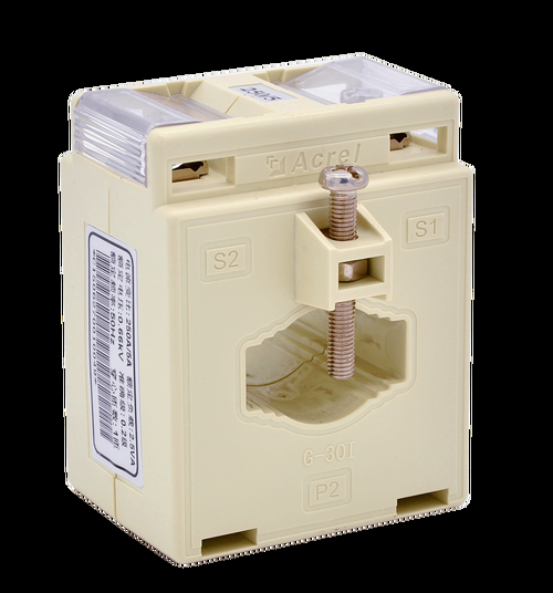
Revenue Metering CT vs Monitoring CT vs Protection CT
Many field mistakes start with a basic misunderstanding: not all CTs are designed for the same purpose.
The right way to distinguish them is by function, error behavior, core characteristics, and winding design.
| CT Type | Main Purpose | Accuracy Focus | Core Behavior | Can It Be Used for Billing? |
|---|---|---|---|---|
| Protection CT (5P/10P) | Relay protection during faults | Maintains performance at high fault current, not light load | Designed to resist saturation under short-circuit conditions | No |
| Monitoring CT (Class 0.5 / 1.0) | Internal measurement and trending | Acceptable for general observation, weaker at low current | General instrument design | Usually no |
| Revenue Grade CT (Class 0.2S / 0.2) | Trade settlement and utility billing | Tight error control across billing range, especially low load | Optimized for precision metering stability | Yes |
Why Protection CTs (5P/10P) Must Not Be Used for Utility Billing
Protection CTs are built for one primary job: feed protective relays correctly during fault conditions. Their design priority is saturation resistance under high current stress, not fine accuracy at 5%, 10%, or 20% of nominal current.
That is why a 5P or 10P CT may perform adequately for relay operation yet still be totally unsuitable for a settlement meter. For CT ratio selection for utility billing meters, fault-oriented CT classes are the wrong tool.
Several utilities explicitly prohibit protection-class CTs on revenue metering circuits, even if the installer claims the meter “seems to read normally.” Utility acceptance is based on design suitability and verified compliance, not visual plausibility.
Why Monitoring CTs (Class 0.5 or 1.0) Are Not Revenue Grade
Monitoring CTs are common in building panels and energy management systems. They are fine for observing load trends, balancing phases, or checking equipment utilization.
But they are not designed to hold settlement-grade accuracy across the low-current range that matters in billing. On nights, weekends, seasonal low-load conditions, or lightly loaded feeders, their error can exceed what a utility or contract settlement framework allows.
This is especially dangerous when the meter itself is highly accurate. Engineers then assume the chain is precise, while the CT has already introduced the dominant error.
Why Revenue Grade CTs (Class 0.2S or 0.2) Are Built for Billing Accuracy
Revenue CTs are built for full-range energy settlement. Their defining advantage is not just the headline class number. It is the fact that error is tightly controlled where actual billing happens, including at low current.
Class 0.2S is particularly important where load fluctuates heavily or spends long periods at light load. That is why it is often preferred in distribution feeders, pole-mounted recloser metering circuits, and mixed-use installations with variable demand.
Current Transformer Accuracy Class for Revenue Metering
Accuracy class is the first and most important selection step. If the class is wrong, no later decision can fully fix the metering risk.
When selecting the current transformer accuracy class for revenue metering, focus on the actual load profile, not just the headline system size. Ask one practical question: How often will this circuit operate at low current?
When to Choose Class 0.2S for Revenue Metering
Choose Class 0.2S where load is variable, seasonal, intermittent, or frequently light. In practical terms, this includes distribution feeders, mixed commercial loads, renewable interconnection points with reverse or fluctuating flow, and pole-mounted recloser metering circuits.
The engineering reason is simple: 0.2S is designed to maintain billing-grade accuracy from approximately 1% to 120% of rated current, depending on the applicable standard and product certification details. That wide low-end performance window is exactly what protects settlement integrity during off-peak operation.
We saw this in a suburban feeder with nighttime current frequently falling below 15% of nominal. The original Class 0.2 CT passed factory documentation, but field analysis showed the utility preferred 0.2S because the feeder spent too much time near the lower threshold. Replacing it with 0.2S eliminated the acceptance issue.
When Class 0.2 Is Acceptable for Stable Industrial Feeders
Class 0.2 can be acceptable where the load is stable and usually remains above the low-end threshold. Examples include dedicated industrial feeders, process lines with predictable operating windows, and continuously loaded supply circuits.
If the current rarely drops below 20% to 30% of rated primary current, a properly selected Class 0.2 CT may satisfy both technical and utility requirements. The key is that the operating profile must be verified, not assumed.
Stable does not mean oversized. Even on industrial feeders, a poorly chosen ratio can push a Class 0.2 CT into an unfavorable operating region.
Why Class 0.5S and Below Should Be Avoided for Settlement Metering
Class 0.5S and lower classes should generally be avoided for settlement metering, especially at main incomers, interconnection points, and utility revenue boundaries.
They may appear cheaper upfront, but the cost difference is insignificant compared with the risk of billing error, rejection by the utility, and retrofit labor. If a circuit is important enough to bill, it is important enough to meter correctly.
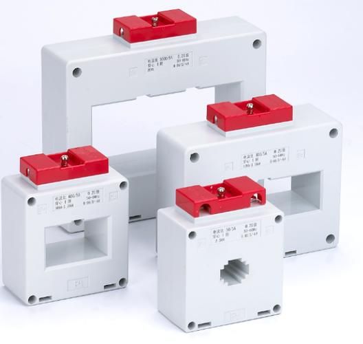
CT Ratio Selection for Utility Billing Meters
The second critical step is ratio selection. This is where many projects go wrong because designers size the CT to maximum theoretical demand or future expansion instead of actual operating current.
Proper CT ratio selection for utility billing meters should be based on the current that the circuit carries most of the time. Revenue CTs are not protection devices to be oversized casually.
The Best Practice Range for Primary Current Loading
As a practical engineering rule, the actual operating current should usually remain within 20% to 100% of the CT’s rated primary current. That keeps the CT in its preferred billing accuracy zone while avoiding chronic overload.
If the normal load is consistently below 20%, the ratio is probably too large. If the normal load is consistently above 100%, the ratio is too small and long-term thermal and accuracy issues become likely.
Why Oversized Ratios Increase Light-Load Metering Error
Oversizing the ratio seems conservative. In billing metering, it is often the opposite.
When a circuit that normally carries 300A is metered with an 800/5 CT “for future growth,” the CT spends most of its life in a low-current operating region. That weakens low-load accuracy and can increase settlement error, especially if the class is not 0.2S.
This is a common hidden cause of unexplained discrepancy between feeder billing totals and downstream energy aggregation.
Real-World Example: 400A Load on 800/5 vs 500/5 CT
Consider a feeder with a typical current of 400A.
With an 800/5 CT, the operating point is only 50% of rated primary current. With a 500/5 CT, the same feeder operates at 80% of rated primary current. For billing accuracy, 80% is generally the healthier position.
| Scenario | Typical Load | CT Ratio | Operating Point | Billing Suitability |
|---|---|---|---|---|
| Option A | 400A | 800/5 | 50% of rated current | Acceptable only if justified, often not optimal |
| Option B | 400A | 500/5 | 80% of rated current | Usually better for revenue metering |
In an actual plant upgrade, changing from 800/5 to 500/5 reduced measured low-load deviation during off-shift hours and aligned the metering chain with the utility’s preferred revenue-grade operating band.
1A vs 5A Secondary Output Selection for Revenue CTs
Secondary current selection is often treated as a routine detail. It should not be.
The choice between 1A and 5A directly affects cable loss, total burden, thermal margin, and practical meter compatibility. This is a major part of revenue grade CT installation best practices.
When 5A Secondary CTs Make Sense
5A secondary is still common and practical where the secondary wiring is short, the metering panel is close to the CTs, and the meter or test equipment is designed around standard 5A inputs.
For compact switchboards with secondary loop lengths under roughly 10 m to 15 m, 5A is often perfectly acceptable if burden remains within rating.
When 1A Secondary CTs Are Better
1A secondary is the better choice when the CT is far from the meter, the wiring route is long, the cable size is limited, or multiple devices are connected in the secondary loop.
The reason is mathematical, not stylistic. Burden from conductor resistance follows S = I²R. Reducing the secondary current from 5A to 1A cuts conductor-related burden by a factor of 25.
That is why 1A is often the smarter engineering choice for long-distance revenue metering circuits.
Real-World Example: How Secondary Current Changes Burden Loss
Assume the total loop resistance of the secondary circuit is 0.4 ohm.
At 5A, burden is S = I²R = 25 × 0.4 = 10 VA.
At 1A, burden is S = I²R = 1 × 0.4 = 0.4 VA.
| Secondary Current | Loop Resistance | Formula | Calculated Burden |
|---|---|---|---|
| 5A | 0.4 ohm | 5² × 0.4 | 10 VA |
| 1A | 0.4 ohm | 1² × 0.4 | 0.4 VA |
That difference alone explains why many long-run billing circuits fail burden checks when 5A is chosen by habit.
Metering Class Current Transformer Burden Calculation
Burden calculation is where design intent becomes engineering truth. A revenue CT can only deliver its rated accuracy if the actual secondary burden stays within its specified capacity.
This is the core of metering class current transformer burden calculation.
What to Include in Total Secondary Burden
Total secondary burden is not just the meter input.
Secondary cable resistance for the full loop length
Terminal blocks
Test switches
Shorting links
Meter input burden
Any transducer or additional connected device in the circuit
Ignoring small components is a classic mistake. On short runs, it may not matter much. On long or already marginal circuits, it can be enough to push the CT outside rated conditions.
Burden Calculation Formula for Revenue Metering CTs
The basic conductor burden formula is S = I²R, where S is burden in VA, I is secondary current, and R is total loop resistance in ohms.
Then add the meter burden and any device burden expressed in VA. The total must remain less than or equal to the CT rated burden.
Example:
Cable burden = I²R
Meter burden = 1.5 VA
Test switch burden = 0.3 VA equivalent
Total burden = cable burden + meter burden + switch burden
Why 20% Burden Margin Should Be Reserved
In practice, do not design right to the limit. Reserve at least 20% spare burden capacity.
This margin protects against cable resistance variation, temperature effects, future meter replacement, extra test accessories, and acceptance disputes over calculated versus measured values.
If a CT is rated 10 VA, a good target is to keep the actual total burden at or below about 8 VA.
Real-World Example: Burden Check for a 5A CT with 30 m Secondary Wiring
Assume a 5A revenue CT feeds a meter 30 m away. The loop length is 60 m because current travels out and back.
Let the cable be copper with an approximate resistance of 0.0074 ohm/m for a small secondary conductor size. Total cable resistance is about:
R = 60 × 0.0074 = 0.444 ohm
Cable burden:
S = I²R = 5² × 0.444 = 11.1 VA
Now add a meter burden of 1.5 VA and test switch burden of 0.3 VA.
Total burden = 11.1 + 1.5 + 0.3 = 12.9 VA
If the CT is rated at 10 VA, the design already fails. Even a 15 VA CT leaves too little margin.
In this situation, there are two rational fixes:
Change to a 1A secondary, which drastically reduces cable burden
Increase conductor size and select a higher-rated VA CT
This exact pattern shows up often in retrofit revenue metering where the CTs remain in old switchgear but the new meter is installed in a remote cabinet.
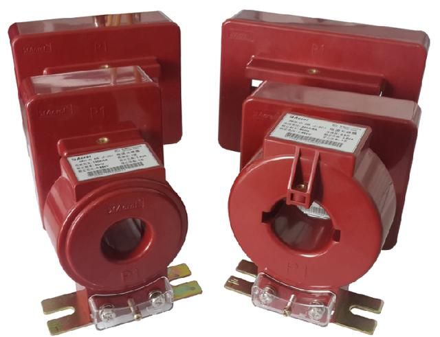
Why Independent Metering and Protection Windings Are Mandatory
For trade settlement, metering and protection should not share the same winding structure. This is not a preference. It is a best-practice requirement for long-term stability.
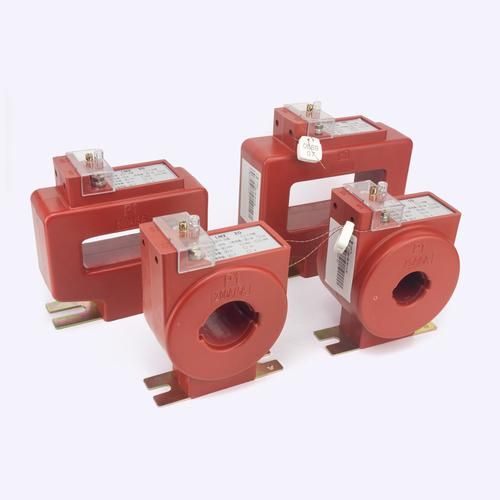
A revenue metering CT should use independent metering and protection windings, or a dual-core design with functional separation.
How Shared Cores and Shared Windings Create Metering Error
When a shared CT experiences high fault current, the magnetic core can retain residual magnetism. That remanence changes the metering behavior afterward.
The result may be subtle but significant: the billing circuit shows persistent error drift even though no obvious physical damage exists. This is one reason utilities dislike designs where metering and protection are combined too closely.
Best Practice: Dual-Core or Dual-Secondary Independent Design
The best practice is straightforward: use a CT with a dedicated metering section and a separate protection section.
This isolates the revenue circuit from relay stress, reduces remanence risk, improves long-term stability, and makes utility review easier. In modern product portfolios, this arrangement is widely available from specialist manufacturers such as Weisho Electric for projects that require clearer separation of billing and protection functions.
Revenue Grade CT Installation Best Practices by Application
Selection is not only about class and ratio. The installation environment matters too.
Best CT Type for New Utility Interconnection and Main Revenue Metering
For new permanent installations, use closed-window, high-accuracy metering CTs. They provide the best mechanical consistency, best magnetic integrity, and typically the strongest confidence in long-term accuracy.
This is the preferred solution for utility interconnection points, main incomers, and permanent billing panels.
Best CT Type for Retrofit Projects Without Full Shutdown
When shutdown is impossible or extremely costly, a high-quality split-core or opening-type revenue-grade CT may be the practical option.
But this only works if the product is genuinely rated for revenue use, with documented 0.2S performance and utility approval where required. Many split-core CTs on the market are monitoring devices, not settlement devices.
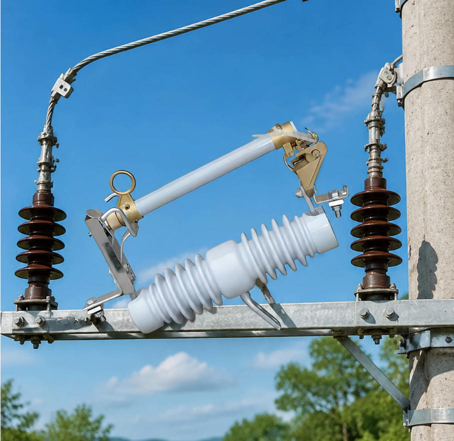
Best CT Type for Pole-Mounted Reclosers and Outdoor Switchgear
For reclosers, pole-mounted switches, and outdoor switchgear, use an outdoor-rated CT with an independent metering winding integrated into the equipment.
These applications are especially sensitive because load can vary strongly while environmental exposure is severe. The CT must handle both.
ANSI IEEE Current Transformer Standards for Metering
Standards matter because utility acceptance rarely depends on marketing claims. It depends on recognized test and performance frameworks.
When evaluating ANSI IEEE current transformer standards for metering, the engineer should review not only the CT datasheet but also the applicable utility metering specification.
Key ANSI and IEEE Metering CT Requirements to Reference
Relevant projects commonly reference standards and requirements related to:
Accuracy class verification
Rated burden and burden testing
Insulation level
Thermal performance
Ratio verification
Winding configuration
Application environment and mounting
Depending on region, ANSI, IEEE, IEC, and local utility documents may all be relevant. The correct approach is to verify what the accepting authority actually requires.
How Utility Acceptance Criteria May Be Stricter Than Minimum Standards
Many engineers learn this the hard way: meeting the base standard is not always enough. Utilities often impose requirements that are stricter than the minimum standard language.
Examples include mandatory 0.2S class, explicit prohibition of shared metering/protection windings, specific burden margins, approved manufacturer lists, or witness testing before energization.
So the safe rule is simple: check utility revenue metering specifications before purchase, not after delivery.
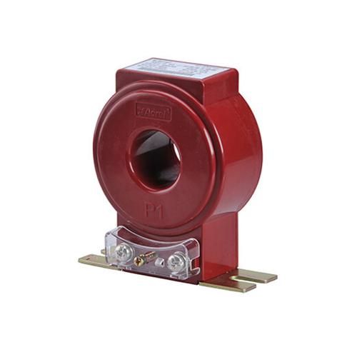
Data Table: Revenue Metering CT Accuracy Class Selection
| CT Class | Typical Accuracy Range Focus | Suitable Use Case | Billing Risk | Recommendation |
|---|---|---|---|---|
| 0.2S | Excellent low-load to full-load control | Variable feeders, reclosers, mixed loads, utility interfaces | Low | Preferred for most revenue metering |
| 0.2 | Strong performance where load is stable | Stable industrial feeders | Low to moderate if ratio is correct | Acceptable where utility permits |
| 0.5S | Moderate precision | Non-settlement internal metering | Elevated | Avoid for utility billing |
| 5P / 10P | Fault current behavior, not billing accuracy | Protection relays | Very high | Do not use for billing |
Data Table: Recommended CT Ratio Selection by Typical Load Profile
| Load Profile | Observed Operating Pattern | Ratio Selection Rule | Preferred Class |
|---|---|---|---|
| Stable industrial load | Usually 60% to 90% of rated current | Match ratio close to long-term current | 0.2 or 0.2S |
| Variable feeder load | Often swings between 15% and 100% | Avoid oversizing; protect low-load accuracy | 0.2S |
| Low-load-heavy circuit | Long periods below 20% | Select the smallest safe ratio for real operation | 0.2S |
| Future expansion concern | Current is low now, maybe higher later | Do not oversize blindly; review staged replacement plan instead | 0.2S |
Data Table: 1A vs 5A Secondary Burden Comparison
| Loop Resistance | Burden at 1A | Burden at 5A | Engineering Implication |
|---|---|---|---|
| 0.1 ohm | 0.1 VA | 2.5 VA | 5A acceptable on short runs |
| 0.2 ohm | 0.2 VA | 5 VA | 5A starts consuming burden quickly |
| 0.4 ohm | 0.4 VA | 10 VA | 1A strongly preferred for long runs |
| 0.6 ohm | 0.6 VA | 15 VA | 5A often impractical for revenue metering |
Data Table: Common CT Selection Mistakes and Corrective Actions
| Mistake | Field Symptom | Billing Impact | Corrective Action |
|---|---|---|---|
| Protection CT used for billing | Utility rejection, unstable low-load readings | Settlement noncompliance | Replace with dedicated 0.2S metering winding |
| CT ratio oversized | Chronic light-load error | Under- or over-billing risk | Resize ratio to real operating current |
| No burden verification | Metering drift, failed test results | Accuracy loss | Calculate loop burden and add 20% margin |
| Metering and protection share winding | Post-fault reading deviation | Long-term settlement instability | Use independent windings or dual-core CT |
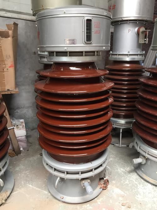
Step-by-Step Five-Step Method to Select a Revenue Metering CT
The fastest way to reduce selection errors is to follow the same engineering sequence every time.
Step 1: Select the Revenue Metering Accuracy Class
Choose 0.2S for fluctuating loads, low-load-heavy operation, feeder metering, and reclosers. Choose 0.2 only when the load profile is stable and utility requirements allow it.
Step 2: Match the CT Ratio to Real Operating Current
Base the ratio on long-term operating current, not only peak demand and not speculative future expansion. Keep normal current mainly inside the 20% to 100% range of rated primary current.
Step 3: Choose 1A or 5A Secondary Based on Wiring Distance
Use 5A for short, simple loops. Use 1A when distance, cable resistance, or multiple connected devices threaten burden performance.
Step 4: Verify Total Secondary Burden Against Rated VA
Calculate the full secondary burden using cable resistance, meter burden, and accessory burden. Keep actual burden at or below rated VA and leave at least 20% spare margin.
Step 5: Confirm Independent Metering and Protection Windings
Require separate metering and protection windings or a dedicated dual-core arrangement. Do not allow fault stress in the protection circuit to compromise the billing circuit.
Proof from Real-World Scenarios and Measured Field Conditions
Good CT selection is measurable. It improves acceptance, reduces rework, and stabilizes billing performance over time.
Case Example: Utility Rejected a Revenue Meter Because a 5P CT Was Installed
At a medium-voltage customer interconnection, the panel builder installed a 200/5 5P10 protection CT because it was already available in stock. The revenue meter and wiring were otherwise correct.
During utility review, the metering package was rejected because the CT class was protection-oriented, not billing-oriented. The fix was to replace it with a 0.2S metering winding CT with independent protection winding.
After replacement, the site passed ratio test, burden verification, and acceptance inspection on the next visit. The original “cost saving” caused a three-week delay.
Case Example: Oversized Ratio Caused Chronic Light-Load Billing Error
In a commercial feeder, average operating current was about 120A, but the installed CT was 400/5 because the designer wanted expansion reserve. Off-peak current often dropped below 60A.
That meant the CT spent much of its time near or below 15% of rated current. After analysis, the ratio was changed to 150/5 with a revenue-grade class. Low-load billing consistency improved and the discrepancy with the building energy management totals narrowed significantly.
Case Example: Long Secondary Cable Run Exceeded Rated Burden
A retrofit meter was added to an existing switchroom, but the billing meter cabinet was 35 m away from the CT location. The original design used 5A secondary on a modest conductor size.
Field calculation showed cable burden alone exceeded the CT’s rated VA. The correction options were reviewed, and the chosen solution was a 1A secondary CT. That reduced burden enough to restore a comfortable margin without increasing cable size or relocating the panel.
FAQ
What accuracy class is required for revenue metering CTs?
For most billing applications, Class 0.2S is preferred, especially where load fluctuates or light-load operation is frequent. Class 0.2 may be acceptable for stable industrial feeders if utility rules allow and the operating current stays in the proper range.
Can a protection CT be used for billing meters?
No. Protection CTs are designed for fault performance and saturation resistance, not settlement-grade accuracy across the billing range.
How do I choose the correct CT ratio for a billing meter?
Select the ratio based on normal operating current, not only maximum demand. As a rule, the CT should operate mainly within about 20% to 100% of rated primary current.
Should I choose a 1A or 5A metering CT?
Choose 5A for short secondary runs and standard local metering panels. Choose 1A for long secondary circuits, higher loop resistance, or burden-sensitive installations.
How do I calculate CT burden for revenue metering?
Calculate conductor burden using S = I²R, then add meter burden and accessory burden such as test switches and terminals. The total must stay within the CT rated VA, and a margin of at least 20% should be reserved.
Why can’t metering and protection share the same winding?
Fault current stress can magnetize the core and create residual error in the metering circuit. Independent windings help preserve long-term billing accuracy and improve compliance with utility metering practice.
Are split-core CTs acceptable for revenue metering?
Only if they are genuinely revenue-grade products with verified accuracy, documented 0.2S or equivalent performance, and utility approval where required. Many split-core CTs are suitable only for monitoring.
Which standards apply to metering class current transformers?
Applicable requirements may include ANSI, IEEE, IEC, and local utility revenue metering specifications. The project engineer should verify all governing documents before procurement.
Final Checklist for Selecting a Revenue Metering CT
Accuracy class: 0.2S for variable or light-load circuits, 0.2 for stable loads if permitted
CT ratio: based on real operating current, not blind future oversizing
Secondary current: 1A or 5A chosen according to loop distance and burden
Burden verification: full calculation including cable, meter, switches, and terminals
Burden margin: at least 20% spare capacity
Winding structure: independent metering and protection windings
Installation type: closed-window for new builds, revenue-grade split-core for constrained retrofit
Standards compliance: meet ANSI, IEEE, IEC, and local utility requirements
If these eight checks are done in the right order, most acceptance failures and post-installation billing disputes can be prevented before the equipment is even purchased.
CTA — Need Help Choosing the Right Revenue Metering CT?
If you are selecting a CT for a utility billing meter, do not rely on guesswork or generic catalog shortcuts.
Send your load current, normal operating range, cable length, conductor size, meter model, and installation scenario. With those inputs, you can get a practical recommendation for the right revenue metering accuracy class, CT ratio, secondary output, rated burden, and independent winding configuration.
Get the selection right before procurement, pass utility acceptance faster, and avoid costly rework later.