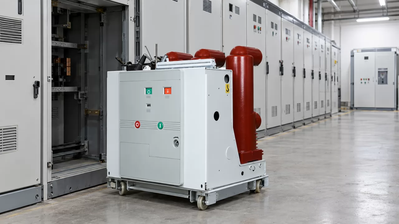
A technician lands a test lead on the wrong pair of terminals in a live medium-voltage switchgear PT circuit, and the transformer's own windings become the only thing limiting the current. That is why a potential transformer secondary cannot be short-circuited: the fault current overheats thin windings within moments and can make the unit fail violently. What follows covers the fault mechanism, the protection and the field controls.
A Potential Transformer runs close to no-load into a high-impedance burden, so its secondary current is normally small.
A short leaves only the PT's low winding impedance in the circuit, and the current rises sharply.
Thin conductors and a small rated output mean no overload capacity. Overheating, insulation failure and explosion can follow.
Fuses on the secondary side, and on the primary side where practical, plus disciplined switching and maintenance keep the fault from happening.
What happens if PT secondary is shorted?
When a PT secondary is shorted, current in the windings rises sharply because nothing outside the transformer limits it any more. The fine-gauge conductors overheat, the insulation breaks down, and in serious cases the PT can explode and injure people nearby. How fast this happens depends on the fault impedance and on whether a secondary fuse clears the fault first.
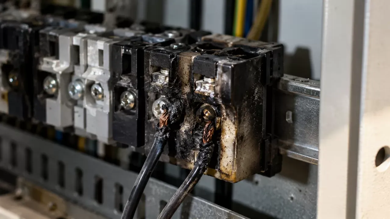
The sequence after the short, roughly in order:
Current surge: secondary current jumps from a fraction of an ampere to many times the rated value, limited only by leakage reactance and winding resistance.
Winding overheating: heat builds faster than a small cast-resin or oil-filled body can shed it.
Insulation breakdown: turn-to-turn insulation degrades first, and an internal fault can then spread to the high-voltage winding.
Violent failure: a cast-resin body can crack. In an oil-filled unit, gas pressure can rupture the tank.
Loss of measurement: voltage at the meters and relays collapses to near zero, so energy metering stops registering correctly.
Protection misbehaviour: relays that need a voltage reference lose it. Distance and undervoltage elements can trip a healthy feeder unless they are blocked.
The last two items matter even when the fuse works. A cleared secondary fault still leaves a busbar or feeder without a valid voltage reference until someone finds and fixes the cause.
Why can't a potential transformer secondary be short-circuited?
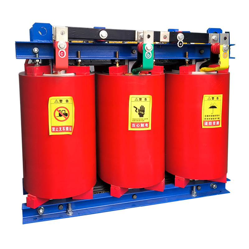
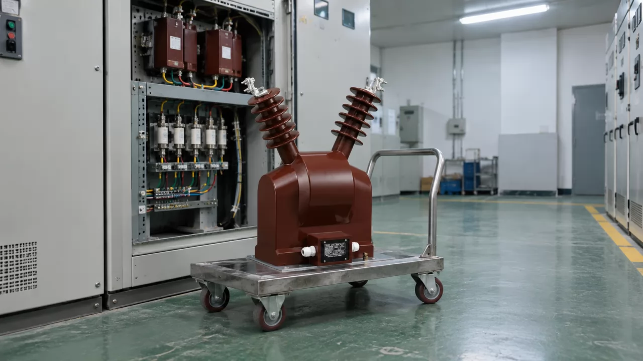
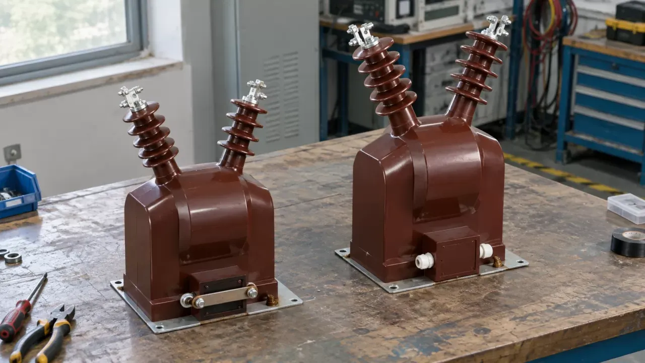
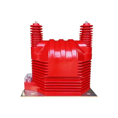
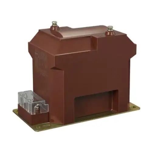
A potential transformer (PT), also called a voltage transformer (VT), is an instrument transformer that steps a primary system voltage down to a standardised secondary voltage for meters and relays. It works on the same principle as a step-down power transformer. The difference is scale: it is built to deliver an accurate voltage into a light load, not to deliver power.
The secondary is commonly rated at 100 V, with 110 V or 120 V used in some regions and under some standards. That is low next to the primary, but it is still a hazardous voltage. It can drive a dangerous current through a person, and it will drive a very large current through a bolted short. The relevant product standards, IEC 61869-3 for inductive voltage transformers and IEEE C57.13 for instrument transformers in North America, define rated secondary voltages and outputs. None of them treats the secondary as touch-safe.
Near no-load by design
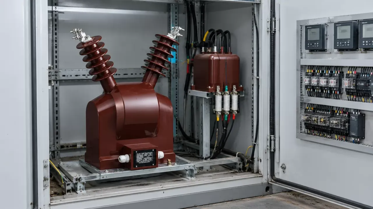
In normal service a PT works close to no-load. Its load is the burden, the total impedance of the meters, relays and wiring connected to the secondary, usually stated in volt-amperes at rated voltage. That impedance is high, so secondary current stays small. Take a PT with a rated output (the burden in VA at which the manufacturer guarantees its accuracy class) of 50 VA at 100 V: at full rated output it delivers only 0.5 A. At or below rated output, the PT runs safely and stays inside its accuracy limits.
Impedance collapse on a short
A short circuit takes the external impedance down to almost zero. The current now flows only through the PT's own windings, and that impedance is deliberately low. A low internal impedance is what lets the PT hold its secondary voltage steady as the burden changes. So the design feature behind its accuracy is the same one behind its fault current. Under a short, the current is limited mainly by leakage reactance and copper resistance, and it rises steeply.
Small rating, thin conductors
A power transformer can survive a through-fault for a short time because its conductors and cooling are sized for heavy current. A PT has neither. Its rated output is small, its conductor cross-section is fine, and it has essentially no overload capacity. Fault current heats the copper, the enamel and interlayer insulation soften and fail, turns short together, and the internal fault grows. If the fault spreads to the primary winding, the result is a high-voltage fault inside the switchgear rather than a burnt-out instrument. That is the case where the PT can explode.
Two more terms belong here. Accuracy class is the designation of the maximum permitted ratio and phase-angle error at rated output: metering classes such as 0.2 or 0.5, protection classes such as 3P or 6P under IEC 61869-3. A PT that has been through a short may still give a reading, but its accuracy class can no longer be assumed, so it should be retested or replaced before it goes back into revenue or protection service.
Why is a PT the opposite of a CT?
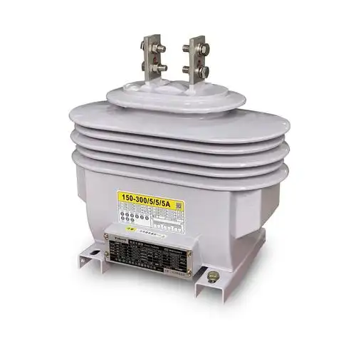
A PT behaves as a voltage source and must never be short-circuited. A current transformer (CT) behaves as a current source and must never be left open-circuited. Opening a loaded CT secondary removes the counter-magnetising current, the core saturates, and the open terminals can develop a voltage high enough to break down insulation and endanger the person who opened them.
So the safe state for each is the reverse of the other. To isolate a CT, you short its secondary first, normally through a shorting test block. To isolate a PT, you open its secondary by removing fuses or opening the isolating links. During commissioning both sets of wiring often run through the same panel and the same terminal rows, sometimes with identical test blocks. A technician who applies CT habits to a PT circuit, such as fitting a shorting link before disconnecting a meter, creates the very fault this article is about. Clear labelling and test blocks that physically differ by circuit type help more than memory does.
Voltage transformer secondary short circuit protection
Voltage transformer secondary short circuit protection works at two levels. A fuse or miniature circuit breaker (MCB) on the secondary protects the PT itself. A fuse on the primary, where the design allows one, protects the network from a failed PT. Neither should disturb metering accuracy in normal service, and both have to be coordinated with the protection that depends on the voltage signal.
PT secondary fuse or MCB
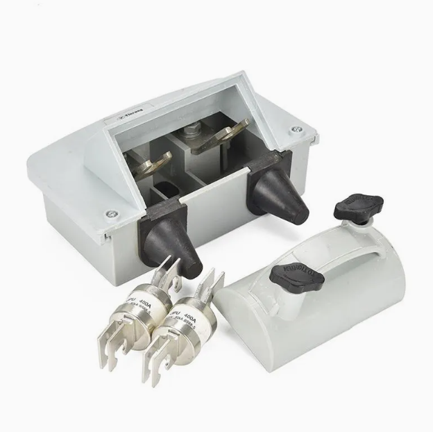
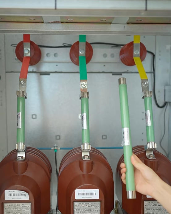
A secondary fuse is a fuse fitted in the ungrounded secondary leads, as close to the PT terminals as practical, so that a fault anywhere in the downstream wiring is cleared before the windings overheat. Placement matters. Wiring that runs unprotected between the PT and the fuse is wiring a fault can reach without the fuse ever seeing it. Common practice is to fit fuses in each phase conductor at the PT terminal box and to leave the grounded conductor unfused, so a fuse operation can never lift the safety ground.
The PT secondary fuse should be sized above the current drawn at full rated burden, with margin for inrush when the circuit is energised, and well below the current the windings can withstand for the fault clearing time. Its own resistance adds a little voltage drop, and on metering circuits that drop counts against the accuracy budget, so fuse type and lead length belong in the same calculation. Where separate metering and protection circuits come off one winding, each branch usually gets its own MCB, coordinated so that a fault on one branch does not take out the other. MCBs with auxiliary contacts have one practical advantage over fuses: they can signal their own operation to the protection scheme.
Primary-side fuses
Where practical, high-voltage fuses on the primary protect the network from faults in the PT's high-voltage winding or its leads. They are not there to protect the PT from secondary faults. Primary fuse ratings are necessarily far above the PT's normal magnetising current, and a secondary short reflected through the ratio is often too small to make them operate in time. Treat the two fuse levels as separate jobs, and do not rely on one to do the other's work.
Relay coordination
When a secondary fuse blows, every voltage-dependent function downstream sees what looks like a system fault. Distance protection sees a collapse in apparent impedance. Undervoltage elements see zero volts. Directional elements lose their polarising quantity. Fuse-failure supervision is the relay function that detects loss of PT secondary voltage without a matching change in current, typically by comparing negative-sequence or zero-sequence voltage against current, or by monitoring MCB auxiliary contacts. Its job is to block the affected elements and raise an alarm, so the scheme does not trip a healthy feeder. Check during commissioning that blocking actually operates and that it alarms locally and remotely. A fuse failure that only blocks, without telling anyone, leaves the feeder without that protection indefinitely.
Field practices that prevent shorts
Most PT secondary shorts are made by people or by neglect, not by the transformer itself. The six controls below fit into an ordinary maintenance and switching routine.
Inspect on a fixed cycle. Test insulation on the PT and its secondary wiring, clean terminal boxes and test blocks, and re-torque connections. A loose terminal that moves over time can end up touching its neighbour.
Follow written switching procedures. Every operation on a PT circuit, whether isolation, meter replacement or testing, should follow a documented sequence. Inspection and maintenance should not depend on whoever happens to be on shift.
Keep the burden within rated output. Total up every connected device and the wiring losses, and compare the sum with the nameplate VA. An overloaded PT runs hot and loses accuracy, and the extra heat stresses insulation that later fails as a short.
Maintain the insulation level. Track insulation resistance between inspections. A downward trend means failure is coming, and it is far cheaper to act on it than on a breakdown.
Fit and maintain protective devices. Install secondary fuses or MCBs and the relay protection that goes with them, and check that the installed fuse rating still matches the drawings. Replacement fuses have a way of growing.
Control the environment. Moisture, dust and high temperature all lower insulation strength. Keep terminal boxes sealed and heaters working where they are fitted, and keep the switchgear room inside its ambient rating.
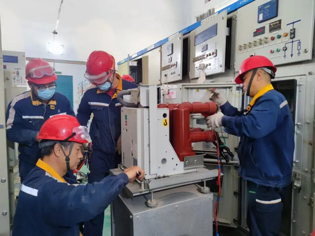
Before touching any PT secondary circuit, test for voltage at the point of work with a tester proved on a known live source. Then open the secondary fuses or links on the PT side. Do not assume a meter that reads zero means a dead circuit. It may be a blown meter fuse with the PT still live behind it.
Also check for back-feed sources. A PT secondary that is paralleled with another PT, or connected through a voltage selection scheme, can be energised from the other side even with its own fuses out.
Common PT secondary myths
The most persistent mistake is treating 100 V as safe to touch. It is a nominal measurement voltage, not an extra-low safety voltage, and it is backed by a source that can supply heavy current for long enough to burn a hand or start an arc. Treat PT secondary wiring with the same isolation discipline as any other live low-voltage circuit.
Close behind it is the belief that PT and CT handling rules are interchangeable because both are "instrument transformer secondaries." They are opposites. Shorting is the safe state for a CT and the destructive state for a PT, and opening works the other way round. A technician who learns one rule and applies it to both will eventually damage something.
Adding another meter or relay is often treated as harmless because each device draws only a few VA. Burden is cumulative, though, and the wiring counts too. Once the total passes rated output, accuracy drops out of class first. Heat follows, and then insulation ageing. Nobody notices until a revenue dispute or a failure forces the calculation.
The last mistake is assuming a fuse makes careful switching unnecessary. A fuse limits damage once a fault exists. It does nothing about the arc flash at the point of the short, the momentary loss of voltage to protection, or a fuse that was replaced with a larger one. Procedures prevent the fault. The fuse only cleans up after it.
Wrap-up for plant engineers
Every PT circuit on site can now be checked against three questions: is it fused correctly at the terminals, is its burden inside rated output, and is there a written procedure that operators actually follow. That covers conventional inductive PTs in medium-voltage switchgear. Capacitor voltage transformers, low-power voltage sensors to IEC 61869-11 and PTs with unusual winding arrangements have their own fault behaviour, so take the manufacturer's data over general guidance there.
FAQ
Can a shorted PT damage connected relays and meters?
Usually not directly, because a short across the secondary removes voltage from the devices rather than adding it. The damage is functional: metering stops recording correctly, and voltage-dependent relays can trip a healthy circuit if fuse-failure supervision is missing. A PT that fails internally and back-feeds primary voltage is a different and far more serious case.
What rating should a PT secondary fuse have?
It should sit above the full-burden secondary current with margin for energising inrush, and well below the winding's short-time withstand. The exact value comes from the PT manufacturer's data and the burden calculation. Check that it coordinates with downstream MCBs and that its voltage drop fits the metering accuracy budget.
Is grounding a PT secondary the same as shorting it?
No. A single ground on one secondary terminal or the star point is standard safety practice and carries no load current. A short appears when a second ground lands on another phase conductor, or when two separately grounded points are bridged, so keep to one deliberate ground point per circuit.
How do you test a PT secondary circuit for faults safely?
Isolate the PT secondary by opening fuses or links, prove it dead, and only then run insulation resistance and continuity tests with sensitive devices disconnected. Never inject test voltage into the secondary while the PT is still connected. The PT will step it up and back-energise the primary at full system voltage.