In high-voltage switchgear, the so-called five preventive interlocks are, put simply, five hard safety locks on operation. They exist to stop the mistakes that hurt people fastest and damage equipment most severely.
On site, this is never theoretical. One wrong switching step can trigger an arc flash, destroy a breaker cell, shut down a feeder, or expose a technician to fatal electric shock. That is why a serious high-voltage switchgear interlock system is not an optional feature. It is the backbone of safe operation.
Why the Five Preventive Interlocks Matter
Ask any commissioning engineer or maintenance supervisor what causes many switchgear incidents, and the answer is often the same: misoperation under pressure. Not always bad equipment. Not always poor design. Sometimes it is a rushed switching sequence, incomplete isolation, or overconfidence during routine work.
The five preventives matter because they are designed to block exactly those human errors. They do not rely on memory alone. They physically or electrically make the wrong action impossible, or at least very difficult.
That is the real value of the five safety interlocks for switchgear. They turn safe procedure into a locked sequence, not just a written instruction in a manual.
What Problem Do the Five Preventives Solve in High-Voltage Switchgear?
Medium- and high-voltage switchgear operates in an environment where the margin for error is tiny. A withdrawable vacuum circuit breaker, a busbar, a cable compartment, and an earthing switch may all be inside one lineup, but each has different operational conditions and hazards.
If someone racks out a breaker under load, the result can be catastrophic contact damage and arc energy release. If someone applies the earthing switch onto a live bus, the fault duty can be violent enough to destroy components instantly.
If a maintenance door opens before voltage absence is verified, the technician may be inches away from energized conductors. In real plants, this is how routine work turns into a life-changing accident.
According to electrical injury studies cited by safety organizations and utility incident summaries, arc flash and electrical contact incidents continue to produce severe burns, lost-time injuries, and fatalities in industrial power systems worldwide. In many of those event reviews, the root causes include incomplete isolation, failure to verify de-energization, or bypassed interlocks.
So the purpose of switchgear preventive interlock mechanisms is simple: block dangerous operating mistakes before they become electrical events.
What Are the Five Preventive Interlocks for High-Voltage Switchgear?
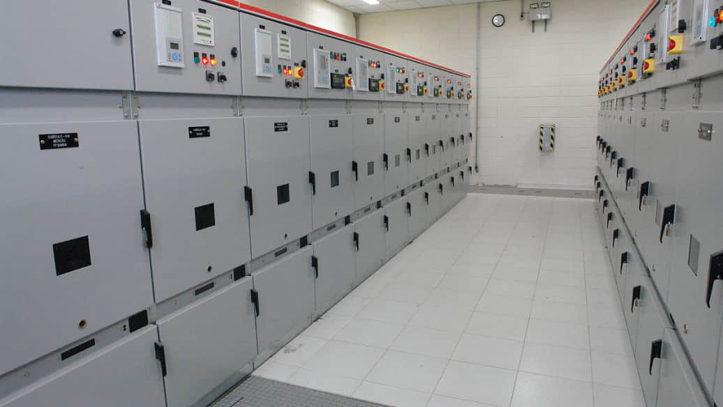
The five preventive interlocks for high-voltage switchgear are the core safety functions that prevent: misopening or misclosing the circuit breaker, moving the withdrawable truck under load, applying the earthing switch on an energized circuit, energizing a circuit while the earthing switch is closed, and entering an energized compartment before isolation and grounding are complete.
This set of high-voltage switchgear operational interlocks is widely recognized across medium-voltage and high-voltage metal-enclosed switchgear practice because it addresses the five most dangerous categories of operator error.
1. Prevent Misopening and Misclosing of the Circuit Breaker
The breaker can only be operated when the withdrawable truck is in the correct position. In practical terms, the truck must be in the test position or service position, depending on the design logic.
If the truck is between positions, the operating path is blocked. This prevents partial engagement, unstable contact conditions, and accidental switching when the primary circuit is not properly connected.
2. Prevent Moving the Truck Under Load
This is one of the most important functions in a withdrawable panel. The truck can only be racked in or out after the circuit breaker is opened.
Why so strict? Because withdrawing a breaker while it is carrying current can cause severe arcing at the primary disconnects. The interlock ensures the switching duty is interrupted by the breaker first, not by the mechanical movement of the truck.
3. Prevent Applying the Earthing Switch on an Energized Bus
If the busbar or cable side is still live, the earthing switch is mechanically or electrically blocked. In many modern designs, both methods are used together.
This protection prevents an operator from intentionally or accidentally grounding a live circuit. Without this interlock, the result can be a direct fault with extreme thermal and mechanical stress.
4. Prevent Energizing with the Earthing Switch Closed
If the earthing switch has not been opened, the truck cannot move into the service position, or the breaker close command remains blocked. Either way, the panel cannot be energized into a grounded path.
This is critical after maintenance. The interlock ensures the grounding step must be reversed before the circuit is returned to service.
5. Prevent Accidental Entry into an Energized Compartment
Rear doors and maintenance panels stay locked until voltage absence is verified and grounding is completed. On many lineups, the live-voltage indication and electromagnetic lock work together to enforce this sequence.
This protects maintenance personnel from stepping into an energized compartment or reaching into a hazardous area before isolation is truly complete.
How Mechanical Interlocks Work in High-Voltage Switchgear
Mechanical interlocks work by direct physical blocking. No signal processing. No software logic. No dependence on communication health. One moving part mechanically stops another moving part.
That is why experienced field engineers often trust mechanical interlocks first. They are visible, understandable, and brutally simple.
When people say mechanical interlocks rely on “hard collision” or “hard blocking,” they mean the mechanism literally prevents an unsafe motion from happening. If a shaft, cam, latch, slide plate, or blocking pin is in the wrong state, the next step cannot proceed.
In safety design, that simplicity is powerful. It reduces ambiguity and removes many failure paths associated with signal loss or incorrect logic states.
Typical Mechanical Interlock Examples
A classic example is that the secondary plug cannot be removed when the truck is in the service position. This prevents loss of control wiring connection while the breaker is engaged.
Another common example is that the truck cannot move into the service position when the earthing switch is closed. The mechanical stop physically blocks racking movement.
In many 12 kV and 24 kV withdrawable switchgear designs, there is also a direct linkage between the breaker operating mechanism and the racking mechanism. If the breaker is closed, the racking handle simply will not turn beyond a small dead movement.
Field crews appreciate this because it gives immediate feedback. No one has to interpret a screen or alarm first. The wrong action just will not happen.
How Electrical Interlocks Work in High-Voltage Switchgear
Electrical interlocks use live-status signals, permissive circuits, auxiliary contacts, electromagnetic locks, and control logic to prevent unsafe actions. They are especially useful where the safety condition depends on voltage presence, remote status, or multi-panel coordination.
For example, a voltage presence indicating system can detect that the busbar is still energized. That signal can then block earthing switch operation, inhibit door release, or keep an electromagnetic lock energized.
Electrical interlocks are not just about one panel. In more advanced systems, they can coordinate with adjacent panels, bus couplers, ring-main arrangements, and incoming feeders so one incorrect operation does not cascade across the lineup.
Typical Electrical Interlock Examples
A very common example is the voltage presence indicator locking the cabinet door. As long as the circuit is detected live, the electromagnetic lock remains engaged and the rear access door cannot open.
Another example is inter-panel logic. If one compartment is in an unsafe state, a neighboring panel may also be blocked from a related operation. This helps prevent chain errors, especially during bus transfer or sectionalizing work.
In modern digital substations and industrial switch rooms, these functions may also be linked to mimic diagrams, SCADA indications, and alarm events. But good designs still keep the final unsafe action blocked at the cabinet level.
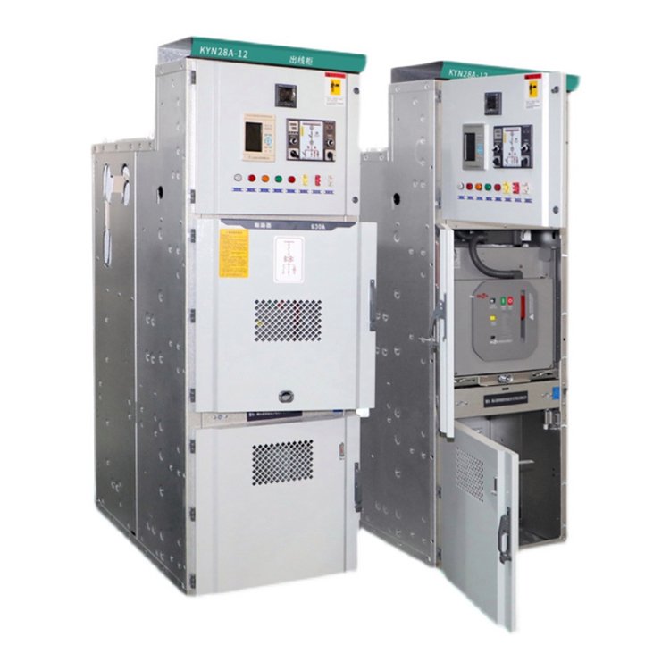
Mechanical vs Electrical Interlocks: What Is the Difference?
The difference is straightforward. Mechanical interlocks stop unsafe actions through physical blocking. Electrical interlocks stop unsafe actions through signal-based logic and controlled locking devices.
Mechanical interlocks are excellent for position-dependent functions. If the breaker is closed, do not allow truck movement. If the earthing switch is closed, do not allow service position entry.
Electrical interlocks are excellent for condition-dependent functions. If voltage is present, do not open the door. If permissive signals are missing, do not allow breaker closing. If another panel is in the wrong state, block a linked operation.
In real switchgear, the best systems use both. A well-engineered high-voltage switchgear interlock system does not force a choice between them. It layers them.
That layered philosophy is what operations teams should look for from serious manufacturers. It is also one reason many project engineers evaluating suppliers such as Weisho Electric pay close attention to whether the interlock design is only schematic-deep or truly cabinet-integrated.
Real-World Examples of Switchgear Interlock Failures and Prevention
Anyone who has spent time in a plant shutdown or utility maintenance window knows that errors rarely happen in ideal conditions. They happen at 2 a.m., during rain, after a protection trip, or under schedule pressure.
That is why field-style cases tell the truth better than theory alone.
Case Example: Truck Racking Attempt with Breaker Closed
In one industrial distribution room, an operator attempted to rack out a 12 kV breaker after assuming the feeder had already been tripped from the control room. Local indication showed the breaker was still closed.
The mechanical interlock prevented any meaningful movement of the truck. The racking mechanism hard-stopped immediately. No arcing occurred, and the error was caught before damage.
Without that interlock, the primary disconnects could have been separated under load. In a metal-enclosed panel, that is exactly the kind of event that escalates into internal arcing and long outage time.
Case Example: Attempt to Close Earthing Switch on a Live Circuit
During maintenance on a feeder lineup, residual assumptions about upstream isolation were wrong. The bus section was still energized from an alternate source.
The voltage presence indication remained active, and the electrical blocking logic prevented earthing switch operation. The operator reported that the earthing handle would not complete travel, and the lock release stayed inhibited.
That small refusal likely prevented a major fault. In post-event review, the interlock did exactly what the electrical switchgear safety procedures were designed to support: stop the dangerous step when the human sequence failed.
Case Example: Unauthorized Access to an Energized Compartment
At a commercial facility with aging medium-voltage gear, a contractor tried to access the cable compartment because he believed the feeder was isolated. The rear door remained locked.
Testing later showed live voltage was still present due to backfeed. The electromagnetic lock and voltage-based door interlock prevented entry until proper isolation, test-for-dead, and grounding were completed.
This is exactly why maintenance doors should never rely on warning labels alone.
Five Preventive Interlocks and Their Safety Function
| PREVENTIVE INTERLOCK | UNSAFE ACTION BLOCKED | TYPICAL INTERLOCK METHOD | RISK AVOIDED |
|---|---|---|---|
| Prevent misopening and misclosing of the circuit breaker | Operating breaker when truck is not in the correct position | Mechanical position latch, auxiliary position contacts, closing permissive logic | Partial connection, contact damage, unstable switching condition |
| Prevent moving the truck under load | Racking in or out with breaker closed | Mechanical blocker tied to breaker mechanism | Arc flash, primary disconnect damage, internal fault |
| Prevent applying the earthing switch on an energized bus | Closing earthing switch while busbar or cable remains live | Voltage detection, key interlock, mechanical block, electromagnetic release logic | Bolted fault, catastrophic short circuit, equipment destruction |
| Prevent energizing with the earthing switch closed | Closing breaker or inserting truck into service while grounded | Mechanical block between earthing switch and truck, closing inhibit circuit | Fault current injection into grounded circuit, breaker trip, equipment stress |
| Prevent accidental entry into an energized compartment | Opening rear or maintenance door before isolation and grounding | Door interlock, voltage presence indicator, electromagnetic lock | Electric shock, arc exposure, fatal contact hazard |
Mechanical vs Electrical Interlock Comparison
| COMPARISON ITEM | MECHANICAL INTERLOCKS | ELECTRICAL INTERLOCKS |
|---|---|---|
| Response method | Physical blocking through cams, latches, pins, linkages | Signal-based inhibition through contacts, relays, sensors, electromagnetic locks |
| Primary strength | Simple, direct, highly visible | Flexible, condition-aware, supports multi-panel logic |
| Typical failure mode | Wear, misalignment, seized linkage, deformation | Loss of control power, failed coil, bad contact, sensor fault, wiring issue |
| Maintenance needs | Lubrication, adjustment, wear inspection, mechanical travel check | Functional testing, signal verification, lock coil check, power supply inspection |
| Best-use scenario | Position-dependent safety blocking | Voltage/status-dependent safety blocking and coordinated logic |
| Reliability philosophy | Hard blocking even without control power | Enhanced logic, but should be backed by mechanical safety where critical |
Recommended Inspection and Maintenance Intervals
| EQUIPMENT USAGE CONDITION | RECOMMENDED INSPECTION INTERVAL | MAIN FOCUS |
|---|---|---|
| Rarely operated switchgear panels | Every 6 months | Mechanical freedom, corrosion, door locks, voltage indicators, earthing switch linkage |
| Frequently operated switchgear panels | Every quarter | Breaker/truck interlock action, auxiliary contacts, operating mechanism wear, electrical permissives |
| Major preventive overhaul | Every 2 years | Complete inspection, insulation testing, withstand voltage test, circuit resistance, mechanism adjustment |
Common Faults in High-Voltage Switchgear Interlocks
When interlocks malfunction, the problem usually shows up in very practical ways. The breaker will not close. The breaker will not open. The earthing switch will not move. The maintenance door refuses to unlock.
Good troubleshooting starts with the sequence logic, not random part replacement.
Breaker Will Not Close
First check the control power supply. A surprising number of “interlock failures” are actually low or lost control voltage, tripped miniature breakers, blown fuses, or loose terminal connections.
Next, verify interlock status. Is the truck fully in the test or service position? Is the earthing switch confirmed open? Are all closing permissive contacts healthy?
In real maintenance practice, technicians also check anti-pumping relays, spring-charged status, close coil continuity, and local/remote selector position. But in many cases, the first fault is still simple: no valid close permissive.
Breaker Will Not Open
If the breaker will not trip, common suspects include trip coil failure, mechanical seizure, or operating mechanism jamming. On older breakers, dried grease and linkage stiffness are frequent contributors.
Check trip circuit continuity, trip voltage at the coil, auxiliary switch state, and mechanical free operation. If the mechanism is binding, electrical commands may be correct while the breaker still refuses to open.
This is why periodic operation checks matter. A breaker that sits untouched for long periods can become unreliable when finally needed under fault conditions.
Earthing Switch Will Not Operate
Do not force it. If the earthing switch refuses to close or open, first check for residual or actual voltage indication. Many designs correctly block operation if the circuit is not proven safe.
Then inspect the linkage condition, release mechanism, shaft alignment, and lock status. Rust, contamination, or bent operating parts can also prevent movement.
Where electromagnetic release is involved, verify the lock coil and release circuit. The fault may be electrical, mechanical, or both.
Door or Maintenance Panel Will Not Unlock
Most often, the cause is one of three things: live-voltage indication remains active, the electromagnetic lock is faulty, or the grounding sequence is incomplete.
Technicians should verify isolation, test for absence of voltage using approved methods, confirm the earthing switch position, and only then investigate the locking device. A stuck door should never be treated as a mere nuisance. It may be the only thing preventing entry into a live compartment.
Testing Requirements for High-Voltage Switchgear Interlock Systems
Interlocks should not be judged by appearance alone. A clean panel can still hide a failed permissive, a weak lock coil, or excessive contact resistance.
The core verification items are insulation testing, withstand voltage testing, and circuit resistance testing. These are not cosmetic tests. They verify whether the equipment can actually withstand service conditions.
Insulation tests help identify moisture ingress, contamination, aging insulation, and developing weakness between phases or to ground. In medium-voltage metal-enclosed gear, this is often one of the earliest indicators of condition deterioration.
Withstand voltage or high-potential testing checks whether the insulation system can survive elevated voltage stress for a specified period. This should always be performed according to the applicable equipment standard, manufacturer guidance, and maintenance plan.
Circuit resistance tests confirm the integrity of the main current path. Elevated resistance at primary disconnects, breaker contacts, or bolted joints leads to overheating, efficiency loss, and eventual failure.
Functional interlock testing should also be part of routine verification. That means actually proving the forbidden action cannot occur. For example:
Attempt racking with the breaker closed and confirm blocking.
Attempt breaker closing with the earthing switch closed and confirm inhibition.
Attempt earthing switch operation with simulated live status where applicable and confirm blocking.
Attempt rear door opening before isolation and grounding and confirm lock retention.
Serious operators document these checks panel by panel, not just lineup by lineup.
Best Practices for Electrical Switchgear Safety Procedures
The best electrical switchgear safety procedures are boring in the best possible way. They enforce the same safe sequence every single time.
A practical rule set looks like this:
Verify equipment identity and switching instructions.
Check actual position indication, not memory.
Isolate the circuit.
Test for absence of voltage using approved test methods.
Apply the earth or grounding device.
Only then access the compartment.
Experienced supervisors also add a simple cultural rule: if an interlock blocks an action, stop and find out why. Do not assume the interlock is wrong and the operator is right.
Another best practice is to train operators on both normal and abnormal indications. Many incidents happen because personnel know the intended sequence but do not know how the gear behaves when a permissive is missing.
In good switchgear operations, speed is never the first goal. Correct sequence is.
How to Choose a Reliable High-Voltage Switchgear Interlock System
When selecting switchgear for a plant, utility, data center, commercial facility, or infrastructure project, buyers often focus heavily on rated voltage, short-circuit capacity, and breaker type. Those are critical, of course.
But from a life-safety perspective, the interlock architecture deserves equal scrutiny.
Look for these features:
Combined mechanical and electrical interlocks, not one or the other alone.
Clear status indication for breaker position, truck position, earthing switch position, and voltage presence.
Maintainable design with accessible linkage inspection points and testable electrical permissives.
Door interlocks that truly enforce isolation sequence, not just symbolic locks.
Documented operating logic that maintenance personnel can verify in the field.
Factory and site acceptance testing that includes actual interlock function checks.
It is also wise to evaluate how the manufacturer supports long-term maintenance. Even strong mechanical designs degrade if spare parts, adjustment guidance, and technical support are absent.
For this reason, many engineering teams prefer suppliers that can explain not just ratings and drawings, but the practical service logic of the interlock system. That level of product maturity is often what separates a catalog product from a reliable operational asset. In procurement discussions, companies like Weisho Electric are often judged not only on equipment specifications, but on whether the interlock scheme is practical in the field, maintainable, and aligned with real operating habits.
FAQ
What are the five safety interlocks for switchgear?
The five safety interlocks for switchgear prevent: operating the breaker in the wrong truck position, moving the truck under load, closing the earthing switch onto a live circuit, energizing while the earthing switch is closed, and entering an energized compartment before isolation and grounding are complete.
Why are mechanical interlocks considered more reliable?
Mechanical interlocks are considered more reliable because they depend on direct physical blocking rather than only control signals or power-dependent logic. If properly maintained, they continue to provide hard prevention even when control power is unavailable.
Can electrical interlocks fail if the power supply is lost?
Yes. Electrical interlocks can fail to function as intended if control power is lost, if a lock coil fails, or if a signal path is damaged. That is why critical safety designs usually combine electrical logic with mechanical blocking.
How often should switchgear interlocks be inspected?
Frequently used units should be checked every quarter, rarely used units every 6 months, and a full overhaul should typically be carried out every 2 years. Actual intervals should still follow site risk, duty cycle, and manufacturer guidance.
What tests are required for high-voltage switchgear safety?
The key tests are insulation testing, high-potential or withstand voltage testing, and circuit resistance testing. In addition, functional testing of the interlock sequence is essential to verify that unsafe operations are truly blocked.
What happens if the earthing switch is closed and someone tries to energize the panel?
The interlock system should block the action. Depending on the design, the truck cannot move into the service position, the breaker cannot close, or both. This prevents energizing a grounded circuit.
Conclusion: Why the Five Preventives Are Essential for Safe Switchgear Operation
The five preventives are not abstract rules. They are the core operating safety logic of switchgear.
Prevent wrong breaker operation. Prevent truck movement under load. Prevent grounding a live circuit. Prevent energizing into a grounded circuit. Prevent entry into an energized compartment. That is the heart of safe switchgear work.
Mechanical interlocks do the hard blocking. Electrical interlocks do the signal-based supervision. Together, they form the foundation of modern high-voltage switchgear operational interlocks.
For operations teams, this means fewer misoperations, lower outage risk, better maintenance discipline, and most importantly, better protection for people standing in front of the equipment.
CTA: Improve Your Switchgear Safety Program
Do not wait for a near miss to review your interlocks. Audit your current lineup now.
Check whether your panels truly implement the five safety interlocks for switchgear. Review your inspection intervals. Re-test insulation, withstand voltage, and circuit resistance. Confirm that door locks, earthing switch blocks, breaker permissives, and truck interlocks work exactly as intended.
If any part of that answer is uncertain, act today. Bring in a qualified switchgear specialist, perform a full safety review, and correct weak points before they become incidents.
Your switchgear should not depend on memory alone. It should make dangerous mistakes impossible.