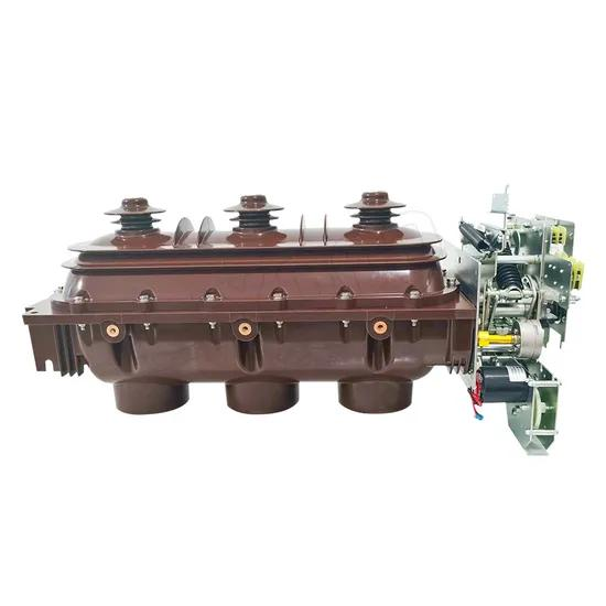
In a medium-voltage switchgear panel, the control circuit of a vacuum circuit breaker is not just a convenience layer. It is the logic core that decides whether the breaker may close, must trip, or must refuse a dangerous repeat operation.
The three most important protection mechanisms in that logic are spring charging, interlock operation, and anti-pumping. In practical engineering terms, they work together to ensure that the breaker closes only when stored energy is ready, refuses unsafe close commands, and does not fall into destructive repeated close-open cycling.
This is why experienced commissioning engineers do not treat these functions as optional. They are basic safety architecture for VCB control circuit protection and safety features.
How a VCB Control Circuit Prevents Misoperation
A vacuum circuit breaker uses a vacuum circuit breaker spring charging mechanism to store the mechanical energy needed for a reliable closing operation. Once the closing spring is fully charged, a limit switch such as S4 changes state and confirms that the breaker is ready to close.
The VCB interlock operation in the control circuit then decides whether a closing path is permitted. If the spring is not charged, or if other required conditions are not met, the close circuit is blocked.
The anti-pumping relay function in VCB prevents repeated closing if a close command remains present after a trip. In many schemes, anti-pumping relay KCF picks up and directly cuts off the supply to the closing coil, stopping the breaker from repeatedly closing into a fault.
Put simply:
Spring charging = energy readiness
Interlock = permission logic
Anti-pumping = repeated closing prevention
Why These Three Mechanisms Matter in Vacuum Circuit Breaker Safety
A VCB is expected to interrupt fault current and restore service with precision. That expectation collapses if the close coil energizes with no stored spring energy, if logic allows an unsafe close attempt, or if a stuck close signal causes repeated operations.
These three mechanisms protect the breaker on different levels. The spring-charged status ensures there is enough mechanical force to complete the close stroke. The interlock prevents invalid command execution. The anti-pumping function stops repeated close-trip-close events under fault or control failure conditions.
In field service, this matters because the damage is rarely theoretical. Engineers see overheated close coils, welded auxiliary contacts, scorched terminal blocks, failed relays, and mechanisms worn far ahead of their normal duty cycle.
In severe cases, repeated operations can degrade the entire switchgear cubicle. Mechanical wear, arc byproducts, and heat accumulation can turn a control logic fault into a reliability crisis.
The Core Problem: What Can Go Wrong Without Spring Charging, Interlock, and Anti-Pumping?
Without proper stored-energy logic, a breaker may receive a close command when the closing spring has not been charged. The command is electrically issued, but the mechanism cannot complete the movement correctly.
That leads to incomplete or failed operation. In some designs, it also stresses the closing coil unnecessarily.
Without interlock logic, the breaker may attempt to close despite unsafe or incomplete preconditions. A missing or bypassed auxiliary contact can create false permissive logic that looks fine on paper but fails under live operation.
Without anti-pumping, the problem becomes far more dangerous. Imagine a permanent feeder fault. The breaker closes, sees fault current, and trips immediately through protection.
If the protection output contact or close command path remains stuck, the breaker will try to close again as soon as the mechanism allows. This repeated close-open-close cycling is commonly called pumping or jumping.
That sequence can burn the close coil, overwork the motor-charging assembly, and accelerate mechanical fatigue in the breaker linkage. In older or poorly maintained panels, it can also produce visible contact arcing in the control circuit.
Typical consequences include:
Failed close operation due to no stored energy
False close attempts from weak interlock logic
Repeated trip-close cycling under a maintained close command
Coil overheating or burnout
Premature wear of auxiliary relays and contacts
Switchgear reliability loss during fault recovery
How the Vacuum Circuit Breaker Spring Charging Mechanism Works
The vacuum circuit breaker spring charging mechanism stores mechanical energy in a closing spring. That stored energy is what actually performs the close operation at the speed and force required by the mechanism.
In most medium-voltage VCBs, a charging motor drives the mechanism after power is available or after a close operation has discharged the spring. Once fully charged, a limit switch changes state and signals that the breaker is ready.
When a valid close command is given, the closing latch releases the charged spring. The stored mechanical energy drives the movable parts of the breaker into the closed position.
Immediately after that action, the spring is no longer charged. The limit switch resets, the close permissive path is removed, and the motor starts a new charging cycle.
This sequence is one of the clearest examples of how vacuum circuit breaker closing and tripping logic depends on both electrical control and mechanical readiness.
What Happens When the Spring Charging Limit Switch S4 Closes?
When the spring reaches its fully charged position, limit switch S4 closes. This is a critical event in the control circuit.
First, S4 provides confirmation that the breaker has stored energy available for closing. Second, it enables the closing path so that a close command can actually be accepted. Third, the same status is often sent to the local indication circuit, SCADA, or station monitoring system as an “spring charged” or “charged ready” signal.
In practical panel design, this signal often appears in:
Local mimic diagrams
Relay I/O status points
Remote terminal units
Substation HMI screens
Sequence-of-events records
Commissioning engineers rely on this indication during logic verification. If S4 does not change state correctly, the breaker may appear healthy mechanically but remain unavailable electrically.

What Happens to S4 After the Breaker Closes?
After the breaker performs a close operation, the closing spring releases its stored energy. At that moment, S4 opens again because the spring is no longer in the charged position.
This is not just an indication. It is also a protective lockout action inside the control logic.
By opening, S4 removes the closing permissive and blocks another close attempt until the motor has recharged the spring. This prevents a close command from being executed without stored mechanical energy.
That is a classic example of interlock operation in a VCB control circuit. The logic does not merely report state; it uses state to enforce safe operation.
Typical Spring Recharging Time in Real VCB Applications
In many practical medium-voltage VCB mechanisms, automatic recharging completes in about 0.7 seconds after a close operation. That figure is a realistic field value for spring motor recharge in compact switchgear mechanisms, though actual timing depends on manufacturer design, control voltage, ambient conditions, and mechanism wear.
For operators, this means the breaker is not instantly ready for another close operation the moment it shuts. There is a short but very important interval during which the mechanism is mechanically discharged and electrically interlocked.
That short recharge period is one reason proper auxiliary-contact timing matters. If logic assumptions do not match actual mechanism timing, nuisance alarms or failed permissive conditions may occur.
What Is Interlock Operation in a VCB Control Circuit?
Interlock operation is the control logic that blocks closing unless required conditions are satisfied. In a VCB, that typically includes confirmation that the spring is charged, that the breaker is in the correct position, and that any related permissive contacts are healthy.
The purpose is simple: no close command should be allowed to drive the mechanism unless the breaker is truly ready to perform it safely.
In medium-voltage switchgear, interlock philosophy may involve both electrical and mechanical layers. The electrical logic may look straightforward in a schematic, but in service it is one of the biggest contributors to dependable operation.
Mechanical vs Electrical Interlock in Vacuum Circuit Breakers
Mechanical interlock physically blocks movement. It prevents incompatible states or actions through latches, shafts, shutters, racking mechanisms, and direct linkage restrictions.
Electrical interlock uses contacts, relays, switches, and logic paths to grant or deny control-circuit permission. It decides whether the close coil is allowed to energize.
For example, a mechanical interlock may prevent a breaker from being closed while in an intermediate racked position. An electrical interlock may prevent closing because S4 does not confirm a charged spring or because a trip circuit supervision condition has failed.
Well-designed switchgear uses both. One catches what the other may miss.
How Interlock Prevents Closing Without Stored Energy
The spring-charged contact, typically S4 in this discussion, sits directly in the logic path that enables the close command. If the spring is not charged, S4 remains open, and the close circuit cannot complete.
This means even if an operator presses the close pushbutton or a remote close command is issued from SCADA, the breaker will not close without stored energy. The command is effectively denied by the control circuit.
That is a textbook example of circuit breaker trip close logic enforcing mechanism integrity. It prevents the electrical system from asking the mechanical system to do something it cannot safely do.
What Is Anti-Pumping in a Vacuum Circuit Breaker?
The vacuum circuit breaker anti-pumping function is the feature that prevents repeated closing when a close command remains present during or after a trip event. It is one of the most important safeguards in breaker control design.
When a breaker closes into a permanent fault, the protection system trips it immediately. If the close signal remains applied, the breaker would try to close again as soon as recharge and logic conditions allow.
Anti-pumping stops this. It ensures that one sustained close signal produces only one close attempt. A new close operation will not be permitted until the original close command is removed and then re-applied.
What Does “Pumping” or “Jumping” Mean in Circuit Breakers?
“Pumping” or “jumping” describes a repeated close-open-close cycle. It happens when the breaker keeps receiving a maintained close command while another condition repeatedly trips it.
In practical terms, the breaker closes, protection trips it, the close path is still present, and the breaker attempts to close again. If this cycle continues, damage can occur very quickly.
Field technicians sometimes identify this by rapid mechanism noise, repeated indication changes, or abnormally frequent motor recharge activity. In severe cases, the smell of overheated control components appears before the root cause is isolated.
Why Permanent Faults Make Anti-Pumping Essential
Permanent faults are exactly where anti-pumping proves its value. If a feeder has an unresolved short circuit or downstream equipment failure, every close attempt is followed by an immediate protection trip.
Now add one more failure: the protection output contact or close command path sticks and remains energized. Without anti-pumping, the breaker would repeatedly close into the fault each time the mechanism is able.
This is why the electrical switchgear anti-pumping mechanism is not a luxury. It is a direct defense against equipment destruction.
How the Anti-Pumping Relay Function in VCBs Works
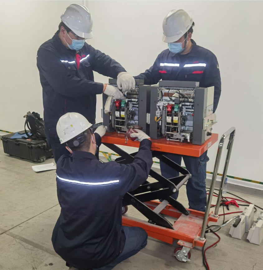
In many control circuits, anti-pumping is implemented by relay KCF. The relay is wired so that once a valid close command initiates breaker closing, KCF picks up and changes the logic state of the close circuit.
Its key job is to block any further energization of the closing coil while the original close signal remains present. In other words, one maintained command equals one closing attempt only.
When the close command is finally removed, KCF resets. Only after that reset can a fresh close command produce another close operation.
This is the heart of anti-pumping relay operation in circuit breakers. It converts a sustained electrical command into a single action instead of an uncontrolled series of actions.
What Happens If the Protection Output Contact Sticks?
If a protection output contact sticks and continues to present a close-related permissive or sustained command condition, anti-pumping relay KCF intervenes. Once it has operated, it directly cuts off the closing coil supply path.
So even though the contact remains stuck, the close coil cannot be re-energized. The breaker stays open after tripping and does not reclose repeatedly.
This protection is especially important in schemes where auxiliary relays, PLC outputs, or protection contacts may fail in the closed state. Good design assumes such failures are possible and builds logic to contain them.
How Anti-Pumping Fits Into Circuit Breaker Trip-Close Logic
The sequence is best understood step by step.
1. The breaker spring is charged, and S4 confirms readiness.
2. A close command is applied.
3. The closing coil energizes, and the breaker closes.
4. If a permanent fault exists, protection trips the breaker immediately.
5. Because the close command remains present, anti-pumping relay KCF picks up and blocks further closing coil energization.
6. The breaker remains open despite the maintained close command.
7. Only after the close command is removed can KCF reset and permit a new close cycle.
This is exactly how prevention of repeated closing in VCB should work in a sound switchgear control scheme.
VCB Closing and Tripping Logic Explained Step by Step
Let us map the complete sequence in practical operating terms.
1. Initial condition: Control power is healthy, the breaker is open, and the charging motor runs if needed.
2. Spring charged: Once stored energy reaches the required position, S4 closes and indicates “spring charged.”
3. Close permissive available: Interlock logic confirms all conditions are safe for closing.
4. Close command issued: A local pushbutton, remote command, or automation output energizes the close path.
5. Closing operation: The close coil releases the mechanism latch and the charged spring drives the breaker closed.
6. Spring discharged: As closing completes, spring energy is consumed, and S4 opens, removing the close permissive until recharge.
7. Automatic recharge: The motor starts and recharges the spring, often in about 0.7 seconds.
8. Normal service: The breaker remains closed until a trip command or protection trip occurs.
9. Trip event: The trip coil opens the breaker.
10. If close command is absent: The breaker remains open, spring recharges, and the circuit awaits the next valid command.
11. If close command remains present: Anti-pumping relay logic blocks further close coil energization until the close command is removed.
This sequence is where vacuum circuit breaker closing and tripping logic becomes more than a schematic. It becomes operational safety.
Spring Charging, Interlock, and Anti-Pumping Functions at a Glance
| Function | Main Purpose | Key Device | Trigger Condition | Control Action | Safety Benefit |
|---|---|---|---|---|---|
| Spring Charging | Store mechanical energy for reliable closing | Charging motor, closing spring, S4 | Breaker open or spring discharged after close | Motor charges spring until S4 indicates ready | Ensures breaker can complete a valid close operation |
| Interlock | Block close commands unless conditions are met | S4, auxiliary contacts, logic relays | Close command with missing permissive | Prevents energizing close coil | Avoids unsafe or impossible closing attempts |
| Anti-Pumping | Stop repeated closing under maintained close command | KCF anti-pumping relay | Close command remains present after breaker trips | Cuts off close coil supply until command is removed | Prevents repeated close-trip cycling and coil damage |
Real-World VCB Control Circuit Events and Expected Responses
| Field Event | Observed Input/Condition | Expected Logic Response | Breaker Result | Risk If Protection Is Missing |
|---|---|---|---|---|
| Normal closing | S4 closed, healthy control power, valid close command | Close coil energizes once | Breaker closes normally, spring recharges | Low |
| Close command with spring not charged | S4 open | Interlock blocks close path | No close operation | Failed or incomplete mechanism action if bypassed |
| Breaker closes into permanent fault | Protection sees fault current immediately | Trip coil opens breaker | Breaker opens rapidly after close | Repeated stress if close signal remains |
| Stuck close contact after fault trip | Close command remains present | KCF anti-pumping blocks reclose | Breaker remains open | Pumping, coil overheating, mechanism wear |
| Missing diode or RC suppression | Inductive switching in control circuit | No voltage spike control | Contacts still switch, but with high stress | Arcing, contact erosion, nuisance failures |
Supporting Protection Components in VCB Control Circuits
Major logic functions get most of the attention, but auxiliary protection components matter greatly in long-term reliability. Two of the most important are the diode across the closing coil and the RC snubber across control contacts.
These components do not replace spring charging, interlock, or anti-pumping. They support them by reducing electrical stress created by inductive loads in the control circuit.
That matters because close coils, trip coils, and relay coils all generate reverse induced voltage when de-energized. If not controlled, that energy shortens component life.
Why a Diode Is Used Across the Closing Coil
A diode connected across the closing coil provides a freewheeling or discharge path when the coil is de-energized. When supply voltage is removed, the coil’s magnetic field collapses and produces reverse-induced voltage.
The diode allows current to circulate safely through the coil-diode loop, limiting the voltage spike. This protects upstream contacts, relay outputs, and electronic devices from transient stress.
In plain language, the diode lets the coil “let go” safely instead of kicking back into the control circuit. This is a simple but highly effective method in DC control systems.
Why an RC Snubber Is Connected Across Control Contacts
An RC snubber places a capacitor and resistor in parallel across control contacts. The capacitor absorbs the initial self-induced electromotive force during switching, while the resistor dissipates the stored energy as heat.
The result is reduced contact sparking and less arc formation when contacts open or close around inductive loads. This extends the service life of pushbuttons, relay contacts, auxiliary contacts, and control switches.
In switchgear that has seen years of operation, missing or failed RC suppression often shows up as blackened contacts, unstable logic transitions, or nuisance malfunctions under load.
Real-World Data and Practical Examples From Switchgear Operation
Engineers trust mechanisms more when numbers and operating behavior line up with field reality. Below are practical values commonly seen in medium-voltage breaker control circuits.
Spring recharge time: about 0.7 seconds in many compact VCB mechanisms after closing
Trip response under permanent fault: effectively immediate from the operator’s perspective once protection picks up and trips
SCADA status usage: spring-charged indication frequently mapped to digital inputs for remote readiness verification
Common failure scenario: close command maintained due to sticky relay contact, selector switch fault, or miswired PLC output
Consider a typical 11 kV indoor switchgear feeder. During a maintenance test, the breaker closes correctly from local control. The mechanism discharges, S4 opens, the motor recharges the spring, and the “charged” indication returns in less than a second.
Now consider a faulted feeder cable. The breaker closes, overcurrent protection trips it almost immediately, and the operator notices repeated attempts only if anti-pumping is absent or defective. In a healthy scheme, KCF blocks reclosing under that same maintained command.
Another field example appears during retrofit work. Older panels are upgraded with modern protection relays, but the original anti-pumping path is not fully reviewed. The relay output remains valid, but the legacy interposing logic no longer resets as intended. The breaker may then exhibit one of the most deceptive faults in switchgear: it works during isolated tests, but pumps under actual trip-close interaction.
This is why experienced manufacturers and panel integrators, including companies such as Weisho Electric, pay close attention not only to primary breaker ratings but also to control logic integrity. In real substations, the reliability reputation of a breaker often depends more on clean control-circuit design than on interrupting chamber technology alone.
Common Design Mistakes in VCB Control Circuit Protection and Safety Features
Most control-circuit failures are not caused by mysterious phenomena. They come from ordinary design or wiring mistakes that escape review.
The first major mistake is missing anti-pumping logic. Some designers assume modern relays or operator discipline will prevent sustained close commands. That is not a protection philosophy; it is a gamble.
The second is incorrect auxiliary contact wiring. If S4 or equivalent charged-status contacts are miswired, the breaker may indicate ready when it is not, or may block valid closing unexpectedly.
The third is weak interlock design. A control circuit that depends on too few permissive conditions can accept invalid commands. A circuit with poorly sequenced permissives can create race conditions during fast close-trip events.
The fourth is inadequate surge suppression. Omitting diodes or RC snubbers may not cause immediate failure, but it accelerates wear and creates hard-to-diagnose intermittent faults.
Additional frequent errors include:
Using the wrong contact type, such as NO instead of NC, in anti-pumping paths
Failing to test logic under simulated fault trip conditions
Ignoring voltage drop across long control wiring runs
Assuming mechanical recharge timing is identical across breaker models
Retrofitting protection relays without reviewing breaker interface logic
These are not small details. They separate a breaker that works once in a workshop from one that remains dependable over years of service.
Best Practices for Prevention of Repeated Closing in VCB Systems
The best way to prevent repeated closing is to verify the entire control sequence, not just individual components. A relay can test healthy on a bench and still fail in real timing logic.
Start with the spring-charged indication. Confirm that S4 changes state exactly when the mechanism reaches charged condition and that this indication is correctly reflected in local and remote status points.
Then test interlock continuity. A close command should be accepted only when every permissive is healthy. Remove the spring-charged condition and verify that the close coil cannot energize.
Next, test the anti-pumping path dynamically. Apply a maintained close signal, force a trip event, and confirm that the breaker does not attempt repeated reclosing. This is the real proof of the vacuum circuit breaker anti-pumping function.
Good practice includes:
Functional testing of S4 under actual mechanism movement
Simulation testing of permanent fault trip with maintained close command
Verification that KCF drops out only after close signal removal
Inspection of diode polarity and RC snubber condition
Review of auxiliary contact timing during close and trip sequences
Documentation of sequence-of-operation results for future maintenance reference
In modern projects, this should be part of FAT, SAT, and periodic maintenance testing. A one-time schematic check is not enough.
Manufacturers with strong switchgear engineering support, including Weisho Electric, are often most valuable when they help customers review not only product selection but also application logic, terminal mapping, and field commissioning checks. That is where many hidden risks are found before energization.
FAQ
What is the purpose of spring charging in a vacuum circuit breaker?
Spring charging stores the mechanical energy needed for a reliable closing operation. The breaker does not rely on the close coil to provide the full closing force; the close coil only releases the mechanism, while the charged spring performs the actual mechanical closing work.
What does S4 do in a VCB control circuit?
S4 confirms that the closing spring is fully charged, enables the closing path, and often sends a “spring charged” status to local or remote monitoring systems. After the breaker closes and the spring discharges, S4 opens again to block reclosing until recharge is complete.
What is interlock operation in a VCB control circuit?
Interlock operation is the logic that allows the breaker to close only when required safe conditions are satisfied. It prevents close commands from being executed when stored energy is unavailable or when other permissive conditions are not met.
What is the anti-pumping relay function in a VCB?
The anti-pumping relay function, often performed by relay KCF, prevents repeated closing when a close command remains present after a trip event. It blocks further supply to the closing coil until the original close command is removed.
What causes pumping in circuit breakers?
Pumping is caused by the combination of a maintained or stuck close signal and a trip event, usually during a permanent fault. The breaker closes, trips, and then attempts to close again because the close command never disappeared.
How does anti-pumping protect switchgear equipment?
Anti-pumping protects switchgear by preventing repeated trip-close cycling, reducing close coil overheating, limiting mechanical wear, and stopping destructive repeated closing into a fault. It is one of the most important safeguards against control-circuit-induced damage.
Why are diode and RC snubber circuits used in VCB control circuits?
They suppress inductive kickback and reduce contact arcing. The diode provides a discharge path for reverse induced voltage from the coil, while the RC snubber absorbs and dissipates switching energy across contacts to reduce sparks and wear.
How fast does a VCB spring charging mechanism recharge after closing?
In many practical applications, the spring charging mechanism recharges automatically in about 0.7 seconds after a closing operation. The exact time depends on the breaker design, control voltage, and condition of the mechanism.
Conclusion: How These Three Safety Mechanisms Work Together
A safe VCB control circuit is built on three coordinated protection ideas: stored-energy readiness, closing interlock, and anti-pumping. The spring charging mechanism ensures the breaker has the mechanical energy to close correctly. The interlock logic ensures it may close only when conditions are valid. The anti-pumping relay ensures that one stuck command cannot force repeated reclosing.
S4 is central to this logic because it both reports and enforces readiness. KCF is central because it breaks the dangerous loop of repeated close-trip attempts. The diode and RC snubber support the whole system by reducing the electrical stress that quietly destroys control components over time.
In other words, these are not isolated features. They are a coordinated defense system inside the breaker control circuit.
Need Help Reviewing Your VCB Control Circuit Logic?
If you are designing, retrofitting, commissioning, or troubleshooting a vacuum circuit breaker panel, do not leave spring-charged permissives, interlock paths, or anti-pumping behavior to assumption. Review the schematic, test the real sequence, and verify what happens under fault and maintained-command conditions.
Now is the right time to audit your VCB control logic. Check S4 status behavior, confirm anti-pumping relay action, inspect diode and RC suppression, and validate the full trip-close sequence before a fault does it for you.
Need expert support? Request a professional review of your switchgear control circuit, compare your existing design against proven field logic, and make sure your breaker will operate safely when it matters most.