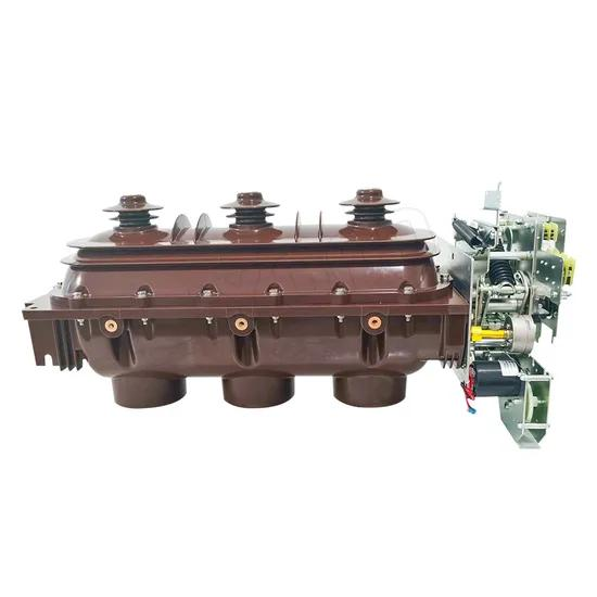
In medium-voltage distribution, very few equipment choices create more confusion than this one: why RMUs use load break switches instead of VCBs in so many projects.
On paper, a vacuum circuit breaker looks stronger. It can interrupt fault current directly, works with protection relays, and supports automation. So why do most ring main units still use load switches, especially in 10 kV distribution networks?
The short answer is simple: most ring main units are not built to be “maximum capability” devices. They are built to be the right-fit devices for branch feeders, terminal transformer protection, urban kiosks, compact substations, and loop distribution points where cost, size, simplicity, and practical adequacy matter more than having full breaker functionality everywhere.
If you have ever walked through a dense residential substation room, a roadside compact substation, or a small industrial park distribution station, this design logic becomes obvious very quickly. Space is tight. Budgets are real. Reliability matters. But overengineering every node with a vacuum circuit breaker often adds cost and complexity without adding proportional value.
What Is a Ring Main Unit and Why Does This Choice Matter?
A ring main unit, or RMU, is a compact set of medium-voltage switchgear used in ring network or terminal distribution systems. In many 10 kV and similar distribution networks, it serves as the switching and sectionalizing point that connects feeders, transformers, and local loads.
In practical terms, an RMU is common in:
Urban residential communities
Commercial buildings
Public infrastructure
Small and medium industrial sites
Box-type substations
Cable branch and loop supply networks
The choice between a load break switch and a vacuum circuit breaker matters because it directly affects:
Capital cost
Panel footprint
Protection philosophy
Installation complexity
Auxiliary power requirements
Maintenance workload
Suitability for automation
That is why the ring main unit load switch vs vacuum circuit breaker question is not academic. It influences the design of thousands of projects every year.
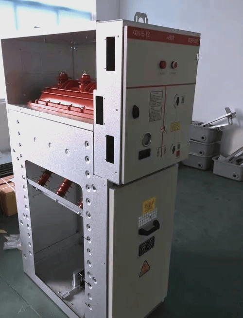
The Core Problem: Why Not Use Vacuum Circuit Breakers Everywhere?
A common misconception in power distribution is this: if a device has more protection capability, it must always be the better choice.
That sounds logical, but in real engineering, it is not how good systems are designed. Good distribution design is not about installing the most powerful device at every node. It is about matching device capability to the actual duty, operating philosophy, and economics of the network.
A vacuum circuit breaker is more capable than a load switch. That part is true.
But a more capable device is not automatically a better RMU choice if:
The node is only a branch or loop section point
Short-circuit interruption is already coordinated elsewhere
Transformer protection can be handled by high-voltage fuses
There is no DC control power available
The site requires very compact equipment
The project has strong cost pressure
In short, RMU design is driven by application fit, not by maximum theoretical functionality.
Short Answer: Why Most RMUs Use Load Switches Instead of VCBs
Most ring main units use load switches instead of vacuum circuit breakers because RMUs usually serve branch or terminal nodes in medium-voltage distribution where normal load switching, compact size, low cost, and simple operation are more important than full fault-breaking capability. When paired with high-voltage current-limiting fuses, a load switch RMU provides an economical and technically adequate solution for many 10 kV transformer and feeder applications.
What Is a Load Switch in an RMU?
A load switch, more precisely a load break switch, is a switching device designed to make and break normal load current. It includes a basic arc-extinguishing mechanism, but it is not intended to independently interrupt high short-circuit current the way a circuit breaker does.
In RMUs, load switches are often used in:
Feeder loop switching
Transformer switching
Sectionalizing duties
Isolation and earthing arrangements
Many RMUs use SF6-insulated load switches because they are compact and practical. A major reason for their popularity is the easy implementation of three-position operation:
ON – current path closed
OFF – current path open
EARTH – cable or circuit earthed for safety
This is extremely useful in field operation. Operators do not just need to switch load. They also need to safely isolate circuits and apply earthing for maintenance.
That three-position function is one reason load break switch advantages in medium voltage switchgear are so often discussed by utilities, contractors, and consulting engineers.
What Is a Vacuum Circuit Breaker?
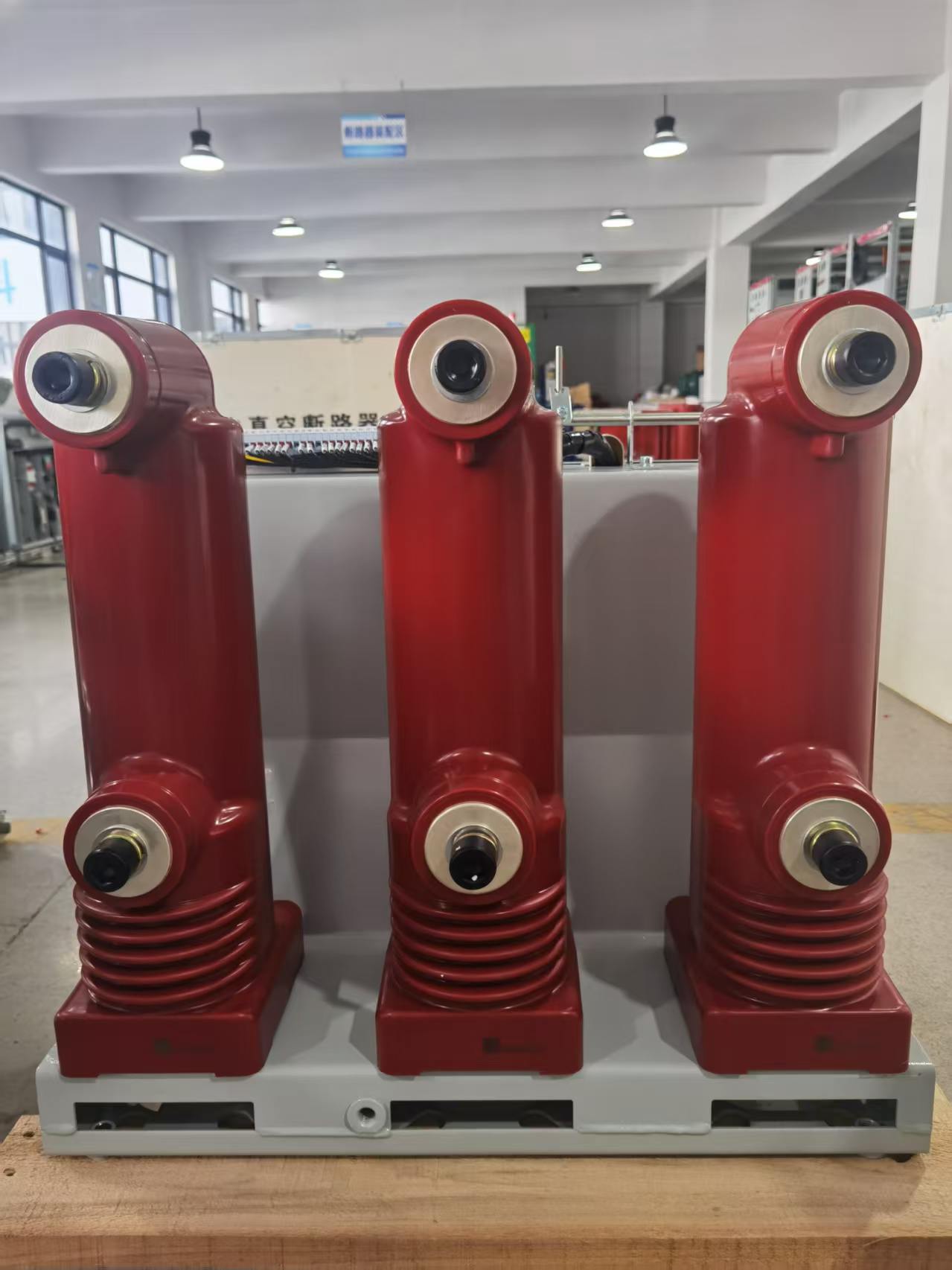
A vacuum circuit breaker, or VCB, is a much more capable switching and protection device. It can switch normal load current and also interrupt fault current directly under short-circuit conditions.
The vacuum interrupter provides excellent arc extinction. But a VCB is not a standalone answer by itself. To function properly in a protection scheme, it normally requires:
Protection relays
Current transformers
Sometimes voltage transformers
Trip and close coils
Auxiliary control power
Interlocking logic
Testing and commissioning of the relay system
In other words, when you specify a VCB, you are usually specifying a broader protection system, not just a switch.
Ring Main Unit Load Switch vs Vacuum Circuit Breaker: Key Functional Differences
The real comparison is not “which device is more powerful?”
The real comparison is: which device matches the duty of this RMU position?
Load Switch: Switching Device With Limited Fault Duty
A load switch is designed to handle routine switching operations under normal conditions. It can close and open load current, and depending on design, it can switch transformer magnetizing current, cable charging current, and certain light inductive or capacitive duties.
However, a load switch does not independently clear high short-circuit current. For transformer protection in an RMU, it is usually paired with high-voltage fuses.
That is why many transformer feeders in compact RMUs use a switch-fuse combination. The switch performs normal operation, while the fuse clears severe fault current.
VCB: Full Protection and Fault-Clearing Device
A VCB can interrupt fault current directly. It works with protection relays that detect overload, short-circuit, earth fault, and other abnormal conditions.
It can also support:
Selective coordination
Remote operation
Motor charging mechanisms
Automatic transfer logic
Reclosing in some applications
SCADA integration
That makes it ideal for more demanding duties. But it also means higher cost and more system complexity.
Why RMU Uses Load Break Switch Instead of VCB: The 5 Core Reasons
This is the central answer buyers, consultants, EPC contractors, and facility owners care about.
Lower Total Project Cost
This is usually the number one reason.
A load switch + fuse arrangement is often materially cheaper than a VCB + protection relay + CTs + auxiliary power system.
In many real 10 kV projects, the difference is not minor. Depending on specification level, brand, and protection scope, a breaker-based RMU feeder can cost roughly 30% to 100% more than a basic load switch feeder, and in some compact transformer protection applications, the gap can be even larger.
Engineers working on multi-unit residential developments know this well. If a project includes 20, 30, or 50 RMU-equivalent panels across multiple compact substations, the cumulative budget impact becomes huge.
For a developer or utility, over-specifying every branch node with a VCB may produce a technically impressive one-line diagram, but often an economically inefficient project.
Smaller Size and Better Fit for Compact RMU Design
RMUs are usually chosen because they are compact. That is their entire value proposition.
Urban distribution sites are often cramped. Electrical rooms in high-rise basements, roadside kiosks, and prefabricated substations do not have generous spare space.
A load switch unit is mechanically simpler and generally more compact than a breaker panel with its added operating mechanism, CT compartment, relay compartment, and associated accessories.
When every panel width matters, load switches fit better.
This is one of the most practical aspects of the ring main unit switching and fault protection differences discussion. It is not only about interrupting current. It is also about fitting the equipment into the real built environment.
No Need for Complex Auxiliary Power
Many load switch RMUs can operate manually. That means no DC battery system is required just to perform the basic switching duty.
This is a major advantage in smaller substations and decentralized installations.
By contrast, a VCB-based system typically needs:
Trip/close control power
Relay power supply
Battery charger or DC source
Additional wiring and supervision
That adds installation work, commissioning steps, spare parts, and lifecycle risk.
Anyone who has had to troubleshoot a failed battery charger in a neglected outdoor substation understands this point immediately. Sometimes the simpler architecture is not primitive. It is smarter.
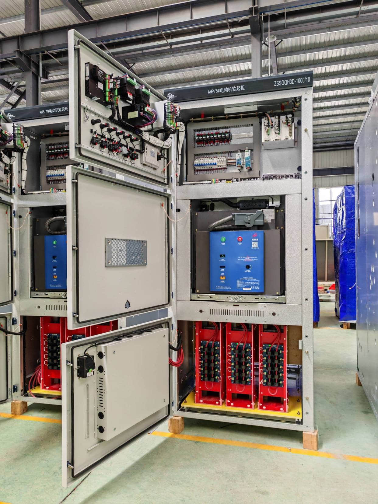
Better Match for Branch and Terminal Distribution Applications
Most RMUs are not located at the primary source node. They are usually at branch points, sectionalizing points, or local transformer supply points.
In those locations, the role of the equipment is often:
Loop continuity
Load transfer
Sectionalizing a faulted cable section
Protecting a local distribution transformer with fuses
That is a different duty from a main incomer or source-side breaker panel.
If the upstream substation already has breaker protection, and the local RMU only needs to switch load and coordinate transformer fault protection, then a load switch plus fuse combination is often entirely appropriate.
This is why, in standard housing developments, small commercial blocks, and ordinary box substations, load switch RMUs dominate.
Fuse Protection Is Fast and Effective for Transformer Faults
Many people underestimate how effective a properly selected high-voltage current-limiting fuse can be.
For transformer fault protection, fuses offer two major benefits:
Very fast fault clearing
Current limiting performance
Current-limiting fuses can reduce let-through energy significantly during severe faults. That lowers thermal and mechanical stress on transformers and associated equipment.
In many transformer applications, this is not a second-best solution. It is a very intentional and proven protection philosophy.
In practice, if one fuse operates, the mechanical striker and trip linkage can trigger the three-phase load switch to open, preventing single-phasing of the transformer.
What Is the Role of Fuse-Switch Combinations in RMUs?
The switch-fuse combination is one of the most important concepts in RMU design.
Here is how the division of labor works:
The load switch handles normal switching, load energization, de-energization, and operational isolation.
The high-voltage fuses handle short-circuit protection and, depending on coordination, transformer-side fault protection and overload-related backup duties.
In a typical transformer protection cubicle:
1. The operator closes the load switch to energize the transformer.
2. The transformer operates normally under load.
3. If a severe internal or downstream fault occurs within the fuse protection zone, the fuse clears it quickly.
4. The fuse striker trips the linked load switch, opening all three phases together.
5. This combination is widely used because it is reliable, compact, and economical.
Why SF6 Load Switches Became Common in RMUs
For many years, SF6 load switches became the mainstream solution in RMUs because they offered a very practical combination of performance and compactness.
The main reasons were:
Easy realization of ON-OFF-EARTH three-position switching
Compact sealed-for-life construction
Good insulation performance in a small volume
Strong resistance to dust, humidity, and harsh ambient conditions
Suitability for compact medium-voltage cable networks
In dense city distribution networks, these advantages were hard to ignore.
That said, today the market is also seeing strong growth in alternative insulation approaches because of environmental pressure related to SF6 use. Still, from a functional and historical perspective, SF6-based load switch RMUs became common because they solved real field problems very efficiently.
RMU Switching and Fault Protection Differences: Load Switch + Fuse vs VCB + Relay
This section gets to the heart of the engineering philosophy.
Normal Load Current Switching
Both load switches and VCBs can perform normal switching duties.
For everyday feeder energization, transformer switching, and loop sectionalizing, a load switch is often fully adequate. If the duty is primarily operational switching rather than repeated fault interruption, there is no automatic reason to move to a breaker.
Short-Circuit Interruption
This is where the key difference appears.
A VCB interrupts the short-circuit current directly when commanded by a relay.
A load switch RMU usually relies on fuses to clear transformer-side fault current. The switch itself is not the primary high-fault interruption device.
That distinction is central to understanding ring main unit switching and fault protection differences.
Isolation and Earthing Functions
RMUs often need practical and safe cable isolation.
Three-position load switch systems are popular because they combine:
Switching
Isolation
Earthing
This makes operation simple and compact, especially in cable distribution systems.
With vacuum interruption technology alone, isolation is not automatically visible or functionally integrated in the same way. Additional isolation arrangements are often needed.
Automation and Remote Control Capability
When a network requires SCADA integration, remote control, motorized operation, advanced relay logic, event recording, or automatic transfer schemes, VCB-based RMUs become more attractive.
That is why utilities and critical facilities may specify breaker-based RMUs for certain nodes even though load switch RMUs remain dominant elsewhere.
Load Switch RMU vs Vacuum Circuit Breaker RMU
| Comparison Item | Load Switch RMU | VCB RMU |
|---|---|---|
| Primary function | Normal load switching, sectionalizing, transformer switching | Load switching plus direct fault interruption |
| Short-circuit breaking ability | Generally not independent; relies on HV fuses | Yes, directly interrupts fault current |
| Protection method | Fuse-based protection, often for transformer feeders | Relay-based protection with CTs and trip logic |
| Isolation/earthing integration | Often easy with three-position ON/OFF/EARTH design | Usually needs additional arrangement depending on architecture |
| Panel size | Smaller and more compact | Larger due to breaker and protection components |
| Auxiliary power need | Often none for manual operation | Typically required for trip/close and relay functions |
| Initial equipment cost | Lower | Higher |
| Maintenance complexity | Lower, fewer active components | Higher, includes relay testing and breaker mechanism checks |
| Best-fit application | Branch nodes, small transformer feeders, compact substations | Main incomers, large transformers, critical loads, automation-heavy nodes |
| Typical decision driver | Economy, compactness, simplicity | Protection capability, selectivity, control, automation |
Cost and Maintenance of Load Switches in RMUs
When project teams compare options, they should not only ask about purchase price. They should also evaluate lifecycle implications.
This is where cost and maintenance of load switches in RMUs often become decisive.
CAPEX Comparison in Typical 10 kV Projects
The exact numbers vary by country, specification, ratings, utility standards, and vendor. Still, the relative pattern is consistent across many markets.
| Typical 10 kV Feeder/Transformer Protection Option | Indicative Relative CAPEX | Notes |
|---|---|---|
| Load switch + HV fuses | 1.0x baseline | Common for standard RMU transformer feeders |
| Motorized load switch + HV fuses | 1.2x to 1.5x | Adds remote operation while retaining simpler protection concept |
| VCB + basic relay + CTs | 1.6x to 2.2x | Depends heavily on relay sophistication and panel architecture |
| VCB + advanced relay + DC system + communications | 2.0x to 3.0x or more | Typical for critical facilities or heavily automated nodes |
These ratios reflect what many EPC teams see in practice: moving from a switch-fuse cubicle to a breaker-relay cubicle changes not only the device cost but also the supporting system cost.
OPEX and Maintenance Complexity
| Maintenance Factor | Load Switch RMU | VCB RMU |
|---|---|---|
| Routine visual inspection | Simple | Simple to moderate |
| Protection testing | Minimal fuse verification and interlock checks | Regular relay secondary injection and protection verification |
| Mechanical complexity | Lower | Higher |
| Auxiliary system checks | Often limited or none | Battery, charger, wiring, trip/close circuits, alarms |
| Spare parts management | Simpler | More extensive |
| Technician skill requirement | Moderate | Higher due to protection and control systems |
| Downtime risk from support systems | Lower | Higher if auxiliary power or relays are neglected |
For organizations with lean maintenance teams, simpler equipment is often safer in the long run because it is more likely to remain properly maintained.
Real-World Example: Residential Community Distribution RMU
Consider a typical urban housing development with several 10/0.4 kV distribution transformers rated between 630 kVA and 1000 kVA. The network is fed by underground cable loops from the local utility.
In this situation, the design priorities usually include:
Compact installation inside kiosk substations or basement rooms
Reasonable project budget
Safe transformer protection
Simple utility operation
Minimal need for complex local control systems
For this kind of project, a common arrangement is:
Two ring feeders with load switch functions
One transformer tee-off using load switch + fuse
Why is this preferred?
Because it matches the duty perfectly. The ring feeders need sectionalizing and loop continuity. The transformer needs economical local protection. The upstream utility substation already has breaker-based feeder protection. There is no strong technical reason to pay for VCBs at every local transformer node.
In real housing projects across Asia, the Middle East, and parts of Europe, this remains one of the most common RMU configurations.
Real-World Example: Why Data Centers and Hospitals Often Use VCB-Based RMUs
Now consider a data center campus or major hospital.
The priorities change completely:
Very high continuity requirements
Selective protection coordination
Remote monitoring and event records
Fast fault discrimination
Integration with BMS, EMS, or SCADA
Planned switching with strong operational control
Here, VCB-based RMUs or breaker-based medium-voltage switchgear are frequently justified.
For example, a hospital with multiple critical transformers, standby generation, ATS coordination, and life-safety loads may need relay selectivity that a fuse-based scheme cannot provide with the same flexibility. A data center may require precise fault coordination, operational visibility, and maintenance bypass planning that strongly favors breaker-based designs.
In these settings, the higher cost is accepted because the cost of an outage is far greater.
Real-World Data: Typical Selection by Application
| Application Scenario | Typical Preferred Technology | Why |
|---|---|---|
| Small distribution transformer feeder, 10 kV / 400 V | Load switch + fuse | Cost-effective transformer protection with compact footprint |
| Urban ring network branch point | Load switch RMU | Simple sectionalizing, small size, low maintenance |
| Main incoming panel or large transformer feeder | VCB RMU or full MV switchgear | Direct fault interruption and relay protection needed |
| Hospital, data center, airport, process plant | VCB-based RMU | High reliability, automation, selectivity, operational visibility |
| Remote compact kiosk with limited auxiliary power | Manual or motorized load switch RMU | Reduces dependence on DC control systems |
| Utility node requiring remote automation and fault management | VCB or advanced motorized LBS depending on standard | Depends on protection philosophy and grid code |
Small Distribution Transformer Feeder
For a local transformer feeder, especially in the common 315 kVA to 1250 kVA range, a load switch with current-limiting fuses is often the most practical choice.
It gives compact, proven protection without the full cost of breaker-based architecture.
Urban Ring Network Branch Point
At an urban cable branch point, the RMU mainly needs to sectionalize and restore supply paths. Compactness and simplicity matter more than having a full breaker relay package.
That is exactly where load switch RMUs shine.
Main Incoming Panel or Large Transformer
Once you get into larger transformer capacities, higher fault levels, more demanding protection selectivity, or source-side duties, VCB-based designs become more appropriate.
This is especially true where direct relay-controlled fault interruption is required.
High-Reliability Critical Facility
If the load is mission-critical, breaker-based RMUs usually justify themselves.
That includes hospitals, airports, semiconductor plants, data centers, and some continuous-process industries where the operational consequences of an outage are unacceptable.
When Should an RMU Use a Vacuum Circuit Breaker Instead?
It is important not to oversimplify. Load switch RMUs dominate many standard applications, but there are clear cases where a VCB is the better choice.
Large Transformer Capacity
As transformer ratings grow, protection requirements often become more demanding.
While the exact threshold depends on local standards and utility practice, many engineers become more inclined toward breaker-based protection once transformer size exceeds 1250 kVA, and especially as fault levels or operational criticality increase.
Frequent Switching or Network Automation
If the node is switched often, remotely controlled, or integrated into a distribution automation scheme, VCB-based solutions may be preferred.
They support more advanced protection and operational logic.
High Reliability or Critical Process Loads
For loads where outages are extremely costly or dangerous, breaker-based RMUs are often the right answer.
This is not because load switch RMUs are unsafe. It is because critical systems often need greater selectivity, event visibility, and controllability.
Utility or Grid Code Requirements
Sometimes the local utility or standard decides the issue.
Certain nodes may be required to use VCBs due to feeder protection philosophy, automation requirements, or internal engineering standards.
In those cases, the design choice is not just technical. It is compliance-driven.
Featured Snippet Section: One-Paragraph Summary
Most ring main units use load switches because they are cheaper, smaller, simpler, and fully adequate for many branch-level medium-voltage distribution duties. In typical 10 kV RMU applications, the load switch handles normal switching while high-voltage fuses provide transformer fault protection, making the switch-fuse combination a compact and economical alternative to a vacuum circuit breaker plus relay system. VCBs are usually reserved for larger, more critical, or more automated nodes where direct fault interruption and advanced protection are necessary.
Common Mistakes When Comparing RMU Load Switches and VCBs
Assuming More Capability Always Means Better RMU Design
This is the most common specification error.
A VCB has more capability, but if the network node does not need that capability, then the result is just extra cost, extra space consumption, and extra maintenance burden.
Ignoring the Need for Relays and Control Power With VCBs
Many buyers compare only the switchgear body price.
That is a mistake. A VCB solution usually means a larger ecosystem: relays, CTs, control wiring, auxiliary power, testing, commissioning, and future maintenance.
Confusing Isolation, Switching, and Fault Interruption
These are different functions.
A good RMU architecture often separates them intentionally. The load switch provides switching and often practical isolation/earthing functionality, while the fuse handles severe faults. That does not make the design inferior. It makes it purpose-built.
FAQ
What is the difference between a load switch and a vacuum circuit breaker in an RMU?
A load switch in an RMU is mainly used for normal load switching, sectionalizing, and isolation-related duties, while a vacuum circuit breaker can do those jobs and also interrupt short-circuit current directly. In practice, load switches usually rely on high-voltage fuses for fault protection, whereas VCBs use relays and trip mechanisms.
Why do most ring main units use load break switches instead of VCBs?
Most RMUs use load break switches because the application usually favors compact size, lower cost, simple operation, and adequate branch-level protection rather than full breaker capability. For many 10 kV feeder and transformer nodes, a load switch plus fuse arrangement delivers the best balance of economy and performance.
Can a load switch interrupt short-circuit current by itself?
Generally, no. A load switch is not intended to independently interrupt high short-circuit current in the same way a circuit breaker does. In RMU transformer applications, it is normally paired with current-limiting high-voltage fuses that clear fault current.
Is a load switch RMU safe enough for transformer protection?
Yes. In many standard medium-voltage distribution applications, a load switch RMU with properly selected HV fuses is specifically designed for transformer protection. It is a long-established and widely used solution for distribution transformers in residential, commercial, and light industrial networks.
When should I choose a VCB-based RMU instead of a load switch RMU?
You should seriously consider a VCB-based RMU when transformer capacity is larger, the load is critical, remote automation is required, or the protection scheme needs direct relay-based fault interruption and better selectivity. Hospitals, data centers, airports, and key utility nodes are common examples.
Are SF6 load switch RMUs still widely used?
Yes, they are still widely used in many markets because they are compact, robust, and practical for medium-voltage distribution. However, environmental regulations and sustainability goals are driving increasing interest in alternative insulation technologies in some regions.
Is a vacuum RMU the same as a VCB RMU?
Not always. “Vacuum” may refer to the arc-interruption technology used in part of the equipment, while a VCB RMU specifically means an RMU architecture based around a vacuum circuit breaker with breaker-type protection and control functions. The terms are related but not automatically identical.
Which option has lower maintenance: load switch RMU or VCB RMU?
In general, load switch RMUs have lower maintenance complexity because they have fewer active protection and control components. VCB RMUs require additional attention to relays, trip circuits, auxiliary power systems, and breaker mechanisms.
Conclusion: The Practical Selection Rule
If you strip away the marketing language and focus on real distribution engineering, the answer is straightforward.
Load switch RMUs dominate standard branch and terminal medium-voltage distribution because they deliver the best balance of technical adequacy, compactness, simplicity, and cost.
A vacuum circuit breaker is absolutely the right choice in some applications. But not in all applications.
That is the key lesson.
Use a load switch RMU where the duty is branch-level switching, compact transformer protection, loop sectionalizing, and practical economy. Use a VCB-based RMU where the node demands higher protection intelligence, direct fault interruption, remote automation, or critical-load reliability.
That is why the market has not “moved on” from load switches. It is because, in a large share of real 10 kV projects, they are still the smarter tool.
For buyers comparing suppliers, a good manufacturer should not just sell the more expensive option. A credible engineering partner should help you select the right protection philosophy for the network. Companies such as Weisho Electric are often evaluated on exactly this point: whether the offered RMU configuration truly matches the project’s operating duty rather than simply maximizing equipment specification.
Planning an RMU project? Do not choose between a load switch RMU and a VCB RMU based on catalog labels alone.
Compare your transformer size, fault level, protection philosophy, site footprint, automation needs, and total lifecycle budget first.
If you want a practical recommendation, have your engineering team review the one-line diagram, transformer ratings, utility requirements, and operating scenario before freezing the specification.
Contact a qualified medium-voltage engineering team now to get a tailored RMU selection recommendation that balances safety, reliability, footprint, and cost—before you overdesign or underprotect your project.