In many utility-scale and commercial PV projects, the combiner box is treated like a simple accessory.
That is a costly mistake.
A properly engineered solar combiner box sits at the heart of the DC side. It determines how multiple strings are collected, how faults are isolated, how lightning energy is diverted, and how quickly O&M teams can find underperforming circuits.
When the design is right, the plant runs safer, cleaner, and with fewer surprises. When the design is wrong, the symptoms show up everywhere: unexplained DC losses, nuisance trips, thermal stress, inverter shutdowns, and long troubleshooting cycles.
This article explains, in practical engineering terms, why the combiner box deserves far more attention in modern solar plant design and maintenance.
The Hidden Role of the Combiner Box in Solar Plant Performance
The combiner box is the DC-side hub of a photovoltaic power plant. Its primary job is simple in theory: collect dispersed string inputs and deliver a centralized DC output to the inverter or downstream DC distribution equipment.
In practice, it does much more than that.
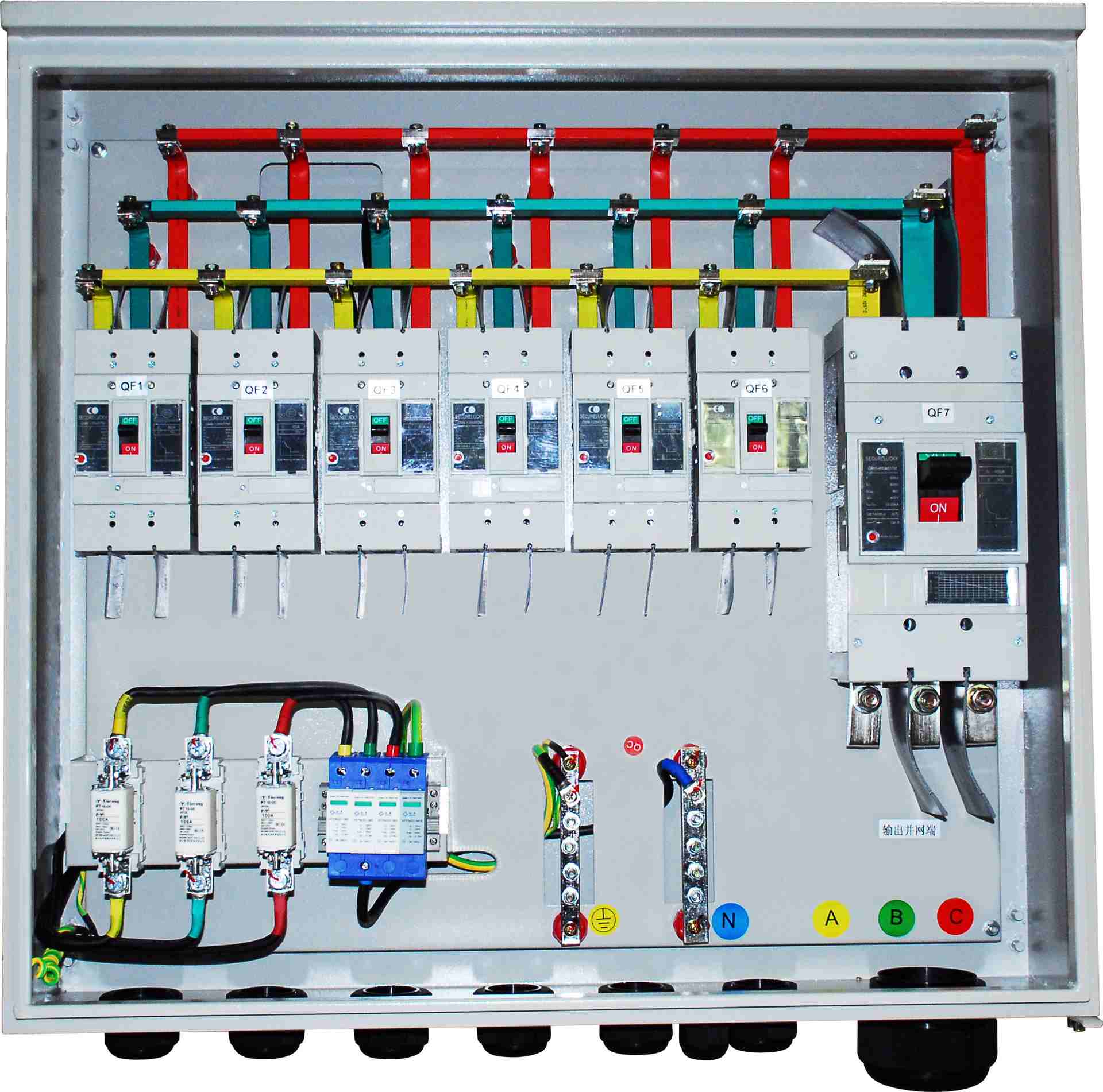
A well-specified box integrates reverse polarity protection, overcurrent protection, fault alarms, surge protection, grounding, isolation, and string-level monitoring. That means it is not just a junction point. It is part of the plant’s control, safety, and diagnostic architecture.
For smaller plants or tightly arranged sites, a single-stage arrangement often sends combined DC circuits directly to the inverter. For large, spread-out sites, a two-stage arrangement can balance cable losses and capital cost more effectively by combining strings first at local boxes and then again through a DC distribution cabinet.
That choice directly affects energy yield, fault response time, and lifecycle cost.
The Real Problem: Why Combiner Boxes Are Often Undervalued
There is a recurring pattern in real projects: major attention goes to modules, inverters, trackers, and transformers, while the combiner box is left to generic specifications.
That usually creates hidden weaknesses.
Poor enclosure design can allow moisture ingress. Incorrect port sizing can overload circuits. Weak grounding can turn a thunderstorm into an inverter replacement event. Missing string monitoring can force technicians to spend hours tracing faults manually under high irradiance.
Even worse, underspecified DC components can pass early acceptance tests and still fail months later under thermal cycling, humidity, and surge exposure.
The result is not just a maintenance issue. It is a plant economics issue.
If one underperforming string loses 10% output and the fault goes unnoticed across dozens of boxes, annual yield loss can become material. If a surge event knocks out multiple inputs and trips inverters, downtime can spread across an entire block.
This is why solar plant DC protection systems cannot be treated as box-checking exercises. The combiner box is part of the power plant’s risk management system.
What Is a Solar Combiner Box and How Does It Work?
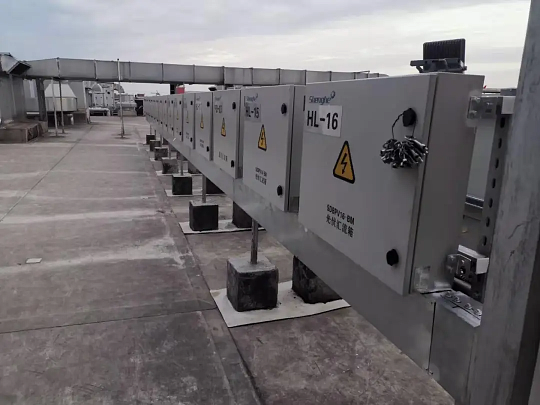
A photovoltaic combiner box is a DC collection device that receives current from multiple PV strings and merges them into a smaller number of output circuits. It allows a solar plant to use a structured architecture: dispersed field inputs, centralized output, integrated protection, and optional communications.
Instead of running every string directly back to the inverter over long distances, the box consolidates inputs closer to the array. This reduces cable complexity and helps control voltage drop.
At the same time, it creates one place to protect and observe the strings.
Core Functions of a Photovoltaic Combiner Box
The core job is current collection, but serious plant design requires more.
Reverse polarity protection to prevent damage from incorrect field wiring
Overcurrent protection to isolate string faults before conductors and equipment overheat
Fault alarms to alert operators to abnormal current, communication, or protective device status
Surge protection to handle lightning-induced transients on the DC side
Grounding to ensure all exposed conductive parts are bonded and safely referenced
Centralized DC output to simplify routing to inverters or DC distribution cabinets
These are the essential solar combiner box safety features that separate a reliable field device from a vulnerable metal enclosure full of parts.
Single-Stage vs Two-Stage Combiner Box Configuration
Configuration matters as much as component quality.
Single-stage combiner box layouts are generally appropriate for plants up to 10 MW or for medium-sized plants with compact layouts. In this design, string inputs are combined once and then sent directly to the inverter.
Two-stage combiner systems are better suited to plants above 50 MW or sites with dispersed array blocks. In that model, local first-stage combiner boxes collect strings, and a second DC distribution stage combines outputs again before the inverter.
The two-stage approach adds complexity and some extra hardware cost, but on large sites it often reduces total DC cable length and achieves a better balance between investment and electrical loss.
Why a Combiner Box Improves Solar Plant Performance
People often ask how a combiner box improves solar plant performance. The answer is not theoretical. It affects measurable operating outcomes.
A well-designed box reduces DC cable losses, improves fault visibility, supports safer isolation, limits surge damage, and shortens maintenance time. That translates into higher uptime and more stable inverter operation.
Every one of those outcomes has financial value.
How a Combiner Box Reduces DC Cable Losses
Placing combiner boxes close to the array shortens the number of long string homeruns. That matters because DC voltage drop is cumulative and expensive over time.
Good design practice keeps DC voltage drop within 3%. By consolidating string circuits near the source, the plant reduces conductor length, lowers resistive losses, and often cuts copper consumption on long routes.
This is especially important in large sites where row-to-inverter distances can become significant. A combiner box in the right place is not just a convenience. It is a loss-control tool.
How Combiner Box Monitoring for Solar Arrays Speeds Troubleshooting
One of the most valuable modern functions is combiner box monitoring for solar arrays.
When each string current is measured through Hall sensors with error no greater than 1%, operators can immediately compare strings under similar irradiance. If one string is down, shaded, disconnected, or suffering connector failure, the current deviation becomes visible in software.
Without this visibility, the O&M team often has to walk rows, isolate circuits, and measure current manually. That can take hours in a utility site and may still miss intermittent faults.
With string-level data, diagnosis can happen in minutes.
How Solar Plant DC Protection Systems Prevent Major Downtime
DC protection is not one device. It is a layered design.
Fuses or breakers protect against overcurrent. Isolators allow safe maintenance disconnection. Surge protective devices limit transient overvoltage. Grounding keeps exposed metal parts bonded and reduces fault risk. Alarms and communication expose abnormalities before they become failures.
When these elements are correctly specified, the plant is far less likely to experience fire risk, equipment damage, or inverter trips caused by DC-side events.
That is the practical value of strong solar plant DC protection systems.
Solar Combiner Box Safety Features That Matter Most
Many spec sheets look similar at first glance.
The details are what determine whether the box survives ten summers, repeated storms, and thousands of thermal cycles.
Enclosure and Ingress Protection Requirements
The enclosure should use Q235 cold-rolled steel plate with thickness of at least 1.5 mm. That gives the cabinet enough mechanical strength for outdoor service and repeated maintenance access.
The enclosure protection level should be at least IP65. Critical cable entries and penetrations should use IP68 cable glands or connectors to prevent water and dust ingress at the weakest points.
Internal layout matters too. A good box leaves enough maintenance space for testing, torque checks, fuse replacement, busbar inspection, and communication work without forcing technicians into unsafe contact with adjacent live parts.
Voltage, Current, and Port Sizing Rules
Electrical sizing must follow field realities, not nominal marketing values.
The voltage withstand level should be at least 1.2 times the string open-circuit voltage. For example, if a string open-circuit voltage is 38.5 V in a given subsystem context, the component withstand level should be at least 46.2 V.
Input current rating should be 1.3 to 1.5 times the string short-circuit current. This provides thermal margin under irradiance variation, manufacturing tolerance, and real operating conditions.
Port quantity must be calculated from:
Total number of strings
Number of downstream DC distribution routes
Maximum inverter input current
String operating and short-circuit current
For example, if an inverter input is rated at 300 A and each string current is 15 A, the maximum practical input quantity is 20 strings for that path.
DC Components and Electrical Performance Standards
All main components should match the plant’s DC class, typically DC1000V in many projects using this design basis.
Component current ratings should be at least 1.2 times the circuit current. DC breakers should have a breaking capacity of at least 10 kA to ensure adequate interruption capability under fault conditions.
Isolation devices should use double-pole mechanical switches. Semiconductor-only isolation is not acceptable for this function.
The main circuit busbar should be tinned copper with current-carrying capability of at least 250 A. Tinning helps resist oxidation, especially in humid or coastal environments.
For electrical integrity, the box should meet these baseline requirements:
Withstand voltage: at least DC1000V
Insulation resistance: at least 1 MΩ, applying the 1000 Ω/V principle
Factory insulation test: 500 V megohmmeter test for at least 1 minute with no breakdown
Lightning Protection and Grounding Design
In outdoor PV plants, surge and grounding design is non-negotiable.
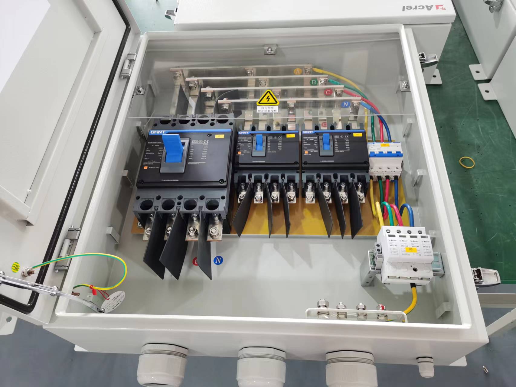
The combiner box should include a DC surge protective device with nominal discharge current of at least 20 kA, response time of 25 ns or less, and a visible degradation indicator. If the SPD has aged or failed, technicians must know immediately.
All metallic parts should be connected using copper cable of at least 16 mm² to the enclosure’s bottom grounding busbar. The grounding resistance should be 4 Ω or less.
A weak ground path turns protective devices into decorations. A low-resistance ground path turns them into real protection.
Combiner Box Design Specifications for Modern Solar Plants
Technical standards only create value when they are translated into practical selection criteria.
EPC teams, developers, and O&M managers should not choose a box by price alone. They should choose it by fit for plant architecture, environmental exposure, current level, monitoring needs, and service strategy.
How to Size Combiner Box Inputs for Real Projects
Let us use a straightforward engineering example.
Suppose a central inverter accepts a maximum DC input current of 300 A. If each string current is 15 A, then the number of strings connected into that path should not exceed 20.
The formula is simple:
Maximum string quantity = inverter maximum input current ÷ string current
So:
300 A ÷ 15 A = 20 strings
In the real world, engineers should also account for current margins, ambient temperature correction, conductor derating, and future expansion strategy.
Undersizing here leads to heat. Oversizing without logic leads to wasted cost and awkward field layouts.
Best Practices for Conductor and Terminal Selection
Copper should be the first choice for conductors and terminations in this application.
Recommended practice includes flame-retardant YJV cables with copper terminals. The conductor cross-section must satisfy three conditions at the same time:
DC voltage drop ≤ 3%
Corrected ampacity ≥ calculated operating current
Short-circuit thermal stability is adequate
The minimum conductor size should not be less than 2.5 mm² copper core.
Every conductor should be placed in labeled tubing or identified clearly, and every terminal number should match the design drawings. This sounds basic, but mislabeled field wiring still causes unnecessary downtime during commissioning and later maintenance.
Installation Standards That Protect Long-Term Reliability
Installation quality is where good designs are either preserved or destroyed.
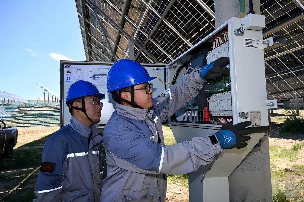
The combiner box should be installed by licensed electricians according to GB50794. Placement should be near the array, in a dry and ventilated location, with mounting height typically between 1.5 m and 1.8 m.
Cables should enter from the bottom wherever possible. Power cables must be routed separately from communication and grounding conductors to reduce interference and improve maintainability.
These details have long-term consequences. Better cable management means lower moisture ingress risk, fewer communication disturbances, easier inspections, and cleaner future repairs.
Photovoltaic Combiner Box Maintenance and Monitoring Best Practices
Photovoltaic combiner box maintenance should never be reactive only.
The best-performing plants treat the box as a monitored asset, not a passive enclosure. That approach improves uptime, shortens fault response, and protects lifecycle value.
What to Monitor Inside a Combiner Box
A modern monitoring setup should track every string current using Hall sensors with measurement error no greater than 1%.
Communication should be via RS485 using Modbus-RTU, with reliable distance greater than 500 m. This is sufficient for most field block architectures when wiring and shielding are done correctly.
The software layer should support:
Per-string current display
Fault alarms
Trend analysis
Historical record queries
Exportable data
Communication status monitoring
This data is not just useful during failures. It also reveals slow degradation, recurring imbalance, seasonal behavior, and post-maintenance performance recovery.
Routine Inspection Checklist for O&M Teams
The field checklist should be disciplined and repetitive.
At minimum, O&M teams should perform quarterly inspections of enclosure seals, grounding condition, SPD status indication, terminal tightness, and visible corrosion or discoloration.
Before the rainy season, insulation should be retested. That timing matters because moisture-related failure risk rises sharply when seals age or cable entries are compromised.
If monitoring shows abnormal string current, technicians should use the monitoring platform first to narrow fault location before opening circuits in the field.
Replacement and Retesting Rules After Repairs
Replacement parts should match the original model and rating.
Substituting a “similar” part with lower DC breaking capacity, lower temperature rating, or incompatible geometry creates hidden risk. After any component replacement, insulation testing must be repeated before the box is returned to service.
This retesting step is often skipped in rushed maintenance. It should not be.
Real-World Data: How Combiner Box Design Impacts Yield, Safety, and O&M
Good combiner box design produces measurable business results.
Below are field-style examples based on common project conditions and accepted engineering thresholds.
Example: DC Loss Reduction Through Better Combiner Box Placement
Consider a 20 MW ground-mounted plant where original layout planning placed inverter blocks far from outer array tables. If average string homerun distance is reduced from 180 m to 75 m by relocating combiner boxes closer to the array, conductor resistance losses drop materially.
In one practical design comparison, keeping the DC voltage drop below 3% avoided unnecessary oversizing on several homerun paths and reduced annual energy loss compared with a longer direct-string routing scheme.
Even a 0.5% to 1.0% DC-side yield improvement is economically meaningful in utility-scale projects.
Example: Faster Fault Location with String-Level Monitoring
Take a plant block with 16 monitored strings in one combiner box. Under stable irradiance, 15 strings operate around 12.8 A to 13.1 A, while one string suddenly falls to 0.4 A.
Without monitoring, a technician may need several hours to inspect fuses, connectors, module plugs, and field wiring across multiple rows. With string-level current monitoring, the exact affected input is identified almost immediately.
That means one truck roll, one targeted inspection, and one much shorter repair window.
Example: Surge and Grounding Protection Preventing Equipment Damage
In thunderstorm-prone regions, boxes with correctly rated SPDs and grounding resistance of 4 Ω or less consistently show lower lightning-related damage rates than installations with weak grounding continuity or no visible SPD health indication.
A typical scenario is this: a nearby lightning event induces a transient on the DC side. A 20 kA or higher SPD responds within 25 ns, diverts energy to the bonded grounding path, and the inverter remains online. In a poorly grounded system, the same event can lead to SPD failure, insulation stress, communication loss, or inverter input damage.
That difference is not academic. It is the difference between continued generation and emergency replacement work.
Recommended Combiner Box Technical Specifications
| Parameter | Recommended Specification | Why It Matters |
|---|---|---|
| Enclosure material | Q235 cold-rolled steel, ≥1.5 mm | Mechanical strength and outdoor durability |
| Ingress protection | Enclosure ≥IP65 | Protection against dust and water ingress |
| Cable entry protection | Critical entries with IP68 connectors/glands | Prevents leakage at vulnerable penetration points |
| System voltage class | DC1000V matched components | Ensures insulation and device compatibility |
| Voltage withstand margin | ≥1.2 × string open-circuit voltage | Protects against real field voltage conditions |
| Input current rating | 1.3 to 1.5 × string short-circuit current | Provides thermal and operational margin |
| Component current rating | ≥1.2 × circuit current | Reduces overload and overheating risk |
| Breaker breaking capacity | ≥10 kA | Fault interruption reliability |
| Isolator type | Double-pole mechanical isolator | Safe DC isolation for maintenance |
| Main busbar | Tinned copper, ≥250 A ampacity | Low resistance and oxidation protection |
| Ground conductor | ≥16 mm² copper cable | Reliable bonding of all metal parts |
| Ground resistance | ≤4 Ω | Effective surge and fault energy dissipation |
| SPD rating | DC SPD, nominal discharge current ≥20 kA | Protection against lightning-induced transients |
| SPD response time | ≤25 ns | Fast surge diversion |
| Monitoring accuracy | Hall sensor current error ≤1% | Accurate string diagnostics |
| Communication | RS485, Modbus-RTU, >500 m | Stable field communication integration |
| Insulation resistance | ≥1 MΩ | Electrical safety baseline |
| Factory insulation test | 500 V megohmmeter, ≥1 min, no breakdown | Confirms pre-delivery insulation integrity |
Single-Stage vs Two-Stage Combiner Box Configuration Comparison
| Comparison Item | Single-Stage Configuration | Two-Stage Configuration |
|---|---|---|
| Typical plant size | Up to 10 MW, or compact medium plants | Above 50 MW, or dispersed medium/large plants |
| Layout suitability | Compact array-to-inverter spacing | Wide or distributed array blocks |
| DC combining method | Direct combine to inverter | First-stage combine plus DC distribution cabinet |
| Initial investment | Lower | Higher |
| Loss optimization potential | Good for short routes | Better for long-distance and dispersed layouts |
| Design complexity | Lower | Higher |
| Maintenance complexity | Simpler | More structured but more devices to manage |
| Expansion flexibility | Moderate | Higher in large block-based plants |
| Best use case | Economical solution for smaller or centralized sites | Balancing cable losses and capex in large sites |
Combiner Box Inspection and Maintenance Schedule
| Inspection Item | Frequency | Acceptable Value / Condition | Common Fault Sign | Corrective Action |
|---|---|---|---|---|
| Enclosure seal and door condition | Quarterly | No cracking, water ingress, or deformation | Condensation, rust, dust buildup | Replace seal, repair door, restore enclosure integrity |
| Grounding continuity | Quarterly | Grounding intact, resistance ≤4 Ω | Loose bond, corrosion, high resistance | Clean, retorque, replace cable, retest grounding |
| SPD status indication | Quarterly | Normal indicator status | Degraded or failed indicator | Replace SPD with same model and retest |
| Terminal tightness and discoloration | Quarterly | No looseness, no overheating marks | Browned insulation, smell, hot terminals | Retorque, replace damaged lugs, reinspect load path |
| String current trend | Continuous via monitoring | Expected similarity between comparable strings | One string low or zero current | Locate string, inspect fuse, wiring, connectors, modules |
| Communication status | Monthly | Stable RS485/Modbus communication | Intermittent data, missing device | Check wiring, address settings, shielding, power supply |
| Insulation resistance | Before rainy season and after repairs | ≥1 MΩ and no breakdown | Low insulation value | Dry, isolate, inspect entries and damaged conductors |
| Replaced component verification | After any repair | Same model/rating as original | Mismatched part installed | Replace with correct component and retest insulation |
How to Choose the Right Combiner Box for Your Solar Plant
The right choice depends on the plant, not on a generic catalog page.
Selection should begin with electrical architecture, then move through environment, communications, maintainability, and long-term serviceability.
At minimum, evaluate:
Plant size
Total string count
Inverter maximum current
Array dispersion and cable routing distances
Site exposure to dust, humidity, salt, and lightning
Need for string-level monitoring
Preferred O&M workflow
Developers and EPCs that treat the combiner box as a design decision instead of a commodity usually see cleaner commissioning and fewer operational surprises later.
Questions EPCs Should Ask Before Finalizing a Combiner Box
What is the actual DC voltage class of the project, and are all components matched to it?
How many strings must each box accept without exceeding inverter and conductor limits?
Will the site benefit more from single-stage or two-stage combining?
Is RS485 with Modbus-RTU sufficient for the SCADA architecture?
What is the local lightning exposure, and is SPD performance adequate?
Can O&M teams safely access the box for routine inspection?
Is internal maintenance space sufficient for real field work?
Are cable entries and enclosure materials suitable for the site environment?
Common Combiner Box Selection Mistakes to Avoid
Underrated components that operate too close to thermal or electrical limits
Poor ingress protection that allows long-term moisture damage
No string monitoring in sites where fault isolation speed matters
Weak grounding design that undermines surge protection
Mismatched port counts that force awkward or overloaded field wiring
Inadequate breaker capacity for DC fault conditions
Unlabeled conductors and terminals that slow commissioning and maintenance
Manufacturers such as Weisho Electric are most useful to buyers when the discussion goes beyond enclosure size and unit price and into full project fit: protection class, monitoring capability, grounding integration, and service practicality.
Proof of Reliability: Factory Testing and Commissioning Requirements
No combiner box should be energized on trust alone.
Factory verification and commissioning checks are the proof that the design has been assembled correctly and will perform safely in the field.
Five tests are essential before delivery or energization:
1. Insulation resistance test
2. Withstand voltage test
3. Continuity and on-off function test
4. SPD action verification
5. Monitoring and communication test
These are not paperwork exercises. They validate the most failure-sensitive parts of the box: insulation, switching, surge path, and data visibility.
Commissioning teams should also verify terminal numbering, communication addressing, alarm reporting, and grounding continuity before the system is declared ready.
FAQ
What does a solar combiner box do in a solar plant?
It combines multiple PV strings into one or more centralized DC outputs while adding overcurrent protection, reverse polarity protection, surge protection, grounding, monitoring, and safe isolation for maintenance.
How does a combiner box improve solar plant performance?
It improves performance by reducing DC cable losses, increasing fault visibility, speeding repairs, supporting stable inverter input conditions, and lowering downtime caused by DC-side faults.
What safety features should a solar combiner box have?
It should include overcurrent protection, reverse polarity protection, DC isolation, surge protection, proper grounding, alarm capability, and a weatherproof enclosure with adequate ingress protection and safe internal layout.
How often should a photovoltaic combiner box be maintained?
It should be inspected quarterly, with seasonal insulation checks before the rainy season, plus immediate follow-up whenever monitoring shows abnormal current behavior, communication loss, or protective device alarms.
When should a solar plant use a two-stage combiner box system?
It is typically the better choice for plants above 50 MW or for sites with dispersed layouts where reducing cable losses and balancing capital cost require a more distributed DC collection strategy.
What data should be monitored in a combiner box?
At minimum, monitor per-string current, fault status, surge device health indication, communication status, historical trends, and exportable operating data for diagnostics and performance analysis.
What happens if a combiner box is undersized?
Undersizing can cause overheating, nuisance trips, accelerated component aging, reduced energy yield, higher failure rates, and increased fire and downtime risk.
Conclusion: A Small Box With a Big Impact
The combiner box may look simple from the outside, but in a functioning solar plant it is a critical design and O&M asset.
It affects safety. It affects uptime. It affects fault response speed. It affects cable losses, inverter stability, and the cost of every maintenance visit.
That is why smart project teams do not buy it as a commodity item. They specify it as part of the plant’s long-term reliability strategy.
If the plant depends on stable DC collection, strong protection, fast troubleshooting, and safe maintenance, then the combiner box deserves engineering attention equal to its importance.
CTA: Audit Your Combiner Box Strategy Before the Next Failure
Do not wait for a burnt terminal, a failed surge device, or an unexplained low-yield block to discover that your combiner box strategy was too weak.
Review your current design now: enclosure protection, DC ratings, port sizing, grounding resistance, SPD performance, communication architecture, and maintenance workflow.
Audit every combiner box in your solar plant before the next failure turns into lost revenue.
If you are planning a new project or upgrading an existing site, now is the time to specify a combiner box system that truly protects yield, uptime, and ROI.