In a 50 Hz network, the arc current between two separating contacts passes through zero about every 10 ms, and each of those zeros gives the breaker a chance to interrupt. It does not complete the interruption. A vacuum circuit breaker restrike is what happens when the breaker loses that chance: the gap goes dark for a few microseconds and then conducts again.
A vacuum circuit breaker restrikes after current zero when the transient recovery voltage across the open contacts rises faster or higher than the dielectric strength the gap is regaining. For capacitor banks, cable feeders and motor circuits, the rate of rise and the peak of that voltage set the real duty. The fault current alone does not.
Current zero is where the recovery race starts. The interruption is not finished at that point.
Interruption holds only if uTRV(t) < Uwithstand(t) at every instant of recovery.
Small capacitive currents can be harder to clear cleanly than large fault currents.
A type test is evidence only for duties that fall inside its TRV envelope.
Current Zero Opens a Window, and the Gap Still Has to Win the Recovery
A breaker has not interrupted the circuit just because the current has reached zero. Current zero gives the gap a short window in which it can recover. The breaker succeeds only if the gap's insulating strength rises faster than the voltage the network places across it, and stays ahead until that voltage settles. The deciding interval is usually measured in microseconds.
The sequence runs like this. The contacts part while current is flowing, so an arc forms straight away. In a vacuum interrupter the arc burns in metal vapour boiled off the contact surfaces, because there is no gas to ionise. That plasma is full of free electrons and ions, and it conducts very well. As the sinusoidal current falls towards zero, the energy going into the arc falls too, and the vapour starts to condense on the contacts and the shield faster than it is being produced.
At current zero the arc stops being fed. Charge carriers recombine or are swept to the electrodes, the vapour density drops, and the withstand voltage across the gap begins to rise from almost nothing. Meanwhile the circuit is still active. Energy stored in the source inductance and in the stray and load capacitance redistributes itself and drives a voltage across the contacts. That voltage often oscillates and often rises steeply. This is the transient recovery voltage, or TRV.
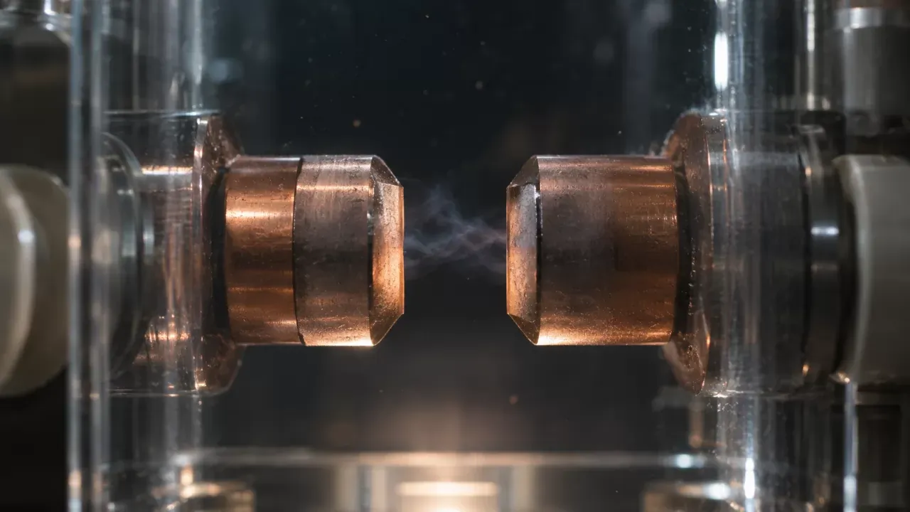
Whether the breaker succeeds comes down to one comparison at every instant of the recovery:
uTRV(t) < Uwithstand(t)
Here uTRV(t) is the voltage actually across the contacts and Uwithstand(t) is the voltage the recovering gap can hold off at that moment. If the inequality holds for the whole transient, the breaker has interrupted. If the TRV crosses the withstand curve even once, the gap breaks down and current flows again. Lasting interruption has to wait for a later zero, or for the protection scheme to step in.
Short Glossary: Terms That Keep the Recovery Race Straight
Several of these terms get used loosely in the field, and that confuses discussions about restrike. The definitions below follow normal IEC usage.
Transient recovery voltage (TRV): the oscillating voltage that appears across the breaker contacts just after current zero, before the system settles to its steady recovery voltage.
Rate of rise of recovery voltage (RRRV): how steeply the TRV climbs, usually given in kV/µs. It controls how much time the gap has to recover.
Dielectric recovery strength: the voltage the gap can withstand at a given instant after current zero, rising as the gap deionises and the contacts move further apart.
Reignition vs. restrike: a breakdown less than a quarter cycle after current zero is a reignition, and a breakdown a quarter cycle or more after it is a restrike.
Late breakdown (NSDD): a non-sustained disruptive discharge, meaning a brief breakdown well after interruption that does not re-establish power-frequency current.
Current chopping: the arc becoming unstable and the current being forced to zero before its natural zero, which matters most in inductive circuits.
Arc extinction: the arc going out at current zero. This is needed for interruption, but on its own it does not complete it.
Vacuum Circuit Breaker Restrike Still Happens, Because Fast Recovery Leaves a Weak Window
The belief: vacuum recovers almost instantly, so restrike only matters for SF₆ or air-blast breakers. The first half has a solid basis. Metal vapour in a vacuum interrupter condenses very quickly once current stops, and that rapid recovery is the main reason vacuum works so well at medium voltage. The conclusion drawn from it is still wrong.
The gap is weak for a short time even after the vapour has gone. The arc roots leave hot spots on the contact surface, and those spots can keep emitting vapour and electrons for a while. Space charge left in front of the electrodes changes the local field. The most persistent problem is microparticles. Arcing, mechanical impact at closing and earlier inrush events can leave small metal fragments loose in the interrupter, or protrusions that concentrate the field. When the recovery voltage pulls a particle across the gap, or a sharp protrusion starts field emission, the gap can break down at a voltage well below its nominal withstand. That can happen milliseconds or even seconds after interruption, which is why late breakdowns and NSDDs are associated so strongly with vacuum devices.
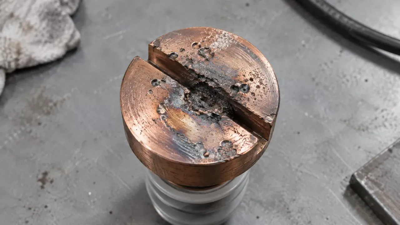
So the vacuum medium is quick to recover. It is not immune to breakdown. The risks also look different from those of gas breakers. In a gas breaker the hard part is usually thermal recovery in the first microseconds. In a vacuum interrupter the early thermal phase is usually easy, and the remaining risk is spread out and statistical. It depends on contact surface condition, particle population and how hard the recovery voltage pushes on a gap that is only a few millimetres to roughly ten-odd millimetres long at medium voltage. A restrike in vacuum is usually a low-probability event. The question for an engineer is whether that probability is low enough for the duty and how often the breaker is operated.
Why Does a Vacuum Circuit Breaker Restrike After Current Zero?
A vacuum circuit breaker restrikes after current zero when the recovery voltage curve crosses the gap's withstand curve. This happens in one of two ways. Either the gap is still partly conducting when a steep TRV arrives, or it has stopped conducting but the contacts are not yet far enough apart, or clean enough, to withstand the voltage that follows.
The useful model has two curves on the same time axis. One is Uwithstand(t). It starts near zero at current zero and rises with deionisation and with increasing contact separation. The other is uTRV(t). It is set by the network: source inductance, bus and cable capacitance, load-side charge and where the fault is. The breaker controls only the first curve. The network decides the second, and that is why the same interrupter can clear one circuit easily and struggle on another.
Residual Conductivity in the First Microseconds Can Cause Thermal Breakdown
The gap does not become an insulator at the instant of current zero. A small post-arc current flows for a short time as the remaining charge carriers are swept out by the rising voltage. If the TRV rises steeply during this phase, it can put energy into that residual conductivity faster than the gap loses it. The gap then heats up and becomes conductive again, which is called thermal reignition. Vacuum interrupters cope well with this phase compared with most gas designs, because the carrier density falls so fast. The risk grows, though, after interrupting high currents with long arcing times. In that case the contact surfaces are hotter and more vapour is left over at current zero. A breaker that clears a terminal fault comfortably can come closer to its limit when a very steep initial TRV is added on top.
Gap Distance, Contact Speed and Field Stress Govern the Dielectric Phase
After the first few microseconds, the question is no longer whether the gap is still conducting. It becomes whether the gap can withstand the electric field. Withstand increases as the gap deionises and as the moving contact keeps travelling, so it depends directly on contact speed and on total stroke. A mechanism that opens slowly leaves the contacts close together just when the TRV reaches its peak, and the field stress at that moment may be too high. The same thing happens with a stroke that has been shortened by wear or poor adjustment. The arcing time matters too. If the contacts separate just before a current zero, the gap is still very short when the first zero arrives, and the breaker may not be able to interrupt at that zero at all. This is why opening speed and stroke are specified and checked as tightly as they are.
TRV Peak vs. Rate of Rise: Two Different Ways to Lose
The peak of the TRV sets how high the voltage climbs. The rate of rise sets how much time the gap has before that voltage arrives. A modest peak that arrives in a few microseconds can beat a gap that would have withstood a far higher voltage a millisecond later. A slow rise to a high peak, as in capacitive switching, tests whether the withstand of the fully opened gap is enough. Fast recovery speed does not help much there.
Both quantities come from the circuit. If two faults have the same RMS current but are fed through different transformers, the inductance-capacitance combinations differ and so do the TRV frequencies. A fault a short distance down an overhead line adds a sawtooth line-side oscillation (the short-line fault case) with a very high initial rate of rise. A series reactor with little capacitance across it can produce a very fast TRV even at moderate current. So two breakers with the same nameplate current can face very different duties. The RMS figure on a fault study does not tell you which duty you have.
A Larger Short-Circuit Current Is Usually Heavier, but It Is Not the Only Measure of Severity
The belief: if a breaker can clear the maximum fault current, it can clear anything smaller. This feels right, and for heating and contact erosion it is broadly correct. Higher current puts more energy into the arc, leaves more vapour and hotter contact surfaces at current zero, and wears the contacts faster. For the rated short-circuit breaking current, it is reasonable to treat bigger as harder.
Restrike, however, depends on how the TRV compares with the withstand curve, and the current magnitude does not decide that comparison. Several low-current duties produce TRVs that are steep, high, or both. Clearing a fault on the secondary of a transformer whose primary capacitance is small can produce an initial rate of rise well above what a terminal fault produces. Interrupting the small inductive current of an unloaded transformer or a stalled motor can lead to chopping, with fast oscillations after it. Clearing capacitive current leaves the full recovery voltage across the gap for a long time, with almost no help from damping.
That is why, if you list vacuum interrupter restrike causes in order of practical importance, short-circuit current comes surprisingly low. Capacitive load, contact surface condition, particle contamination, a slow or short stroke and an unusually fast TRV come first. An interrupter can have a generous short-circuit rating and still restrike on a capacitor bank that draws only a few hundred amperes. These are different stresses, rated separately and tested separately.
VCB Restrike in Capacitor Bank Switching Is Where Small Currents Do Big Damage
When a vacuum breaker de-energises a capacitor bank, the current interrupts at its natural zero. For a capacitive load that zero coincides with the voltage peak, so the bank stays charged to roughly the peak phase voltage, with nowhere to discharge quickly. The source side keeps following the power-frequency sine wave. Half a cycle later the source voltage has swung to the opposite peak, while the load side still holds its trapped charge. The voltage across the open contacts therefore climbs over about 10 ms towards roughly twice the peak system voltage. In an ungrounded or ineffectively grounded bank it can go higher on the first-pole-to-clear.
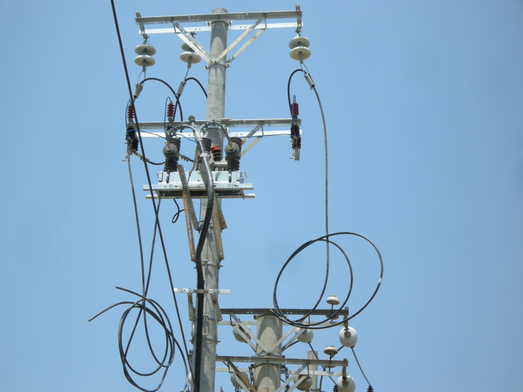
The rise is slow by TRV standards, so this is not a race against a steep front. It is a sustained stress on a gap that has to withstand close to twice the system peak, with whatever particles and surface roughness the interrupter happens to contain. This is why late breakdowns and restrikes are concentrated on capacitive duty. The breakdown probability per operation may be small. But capacitor banks are switched often, sometimes several times a day for voltage or power-factor control, so the small per-operation risk builds up.
The consequences can escalate. A restrike near the peak of the recovery voltage connects a source at one polarity to a capacitor charged at the other. The resulting high-frequency oscillation can drive the bank voltage, in simple theory, to around three times the system peak. If the arc then interrupts at a high-frequency current zero and restrikes again, each repetition can push the voltage higher. Real circuits have damping and arresters that cap this, but the stress on bank insulation, cable terminations, nearby surge arresters and other equipment on the bus can still be severe. One restrike event can also cause cumulative damage that does not show up immediately.
Back-to-Back Banks and Inrush Effects on Contact Surfaces
When one bank is energised beside another bank that is already charged, the inrush current comes mostly from the neighbouring bank through a very low inductance. It can have a high peak and a high frequency. When the contacts close, or pre-strike just before touching, this current passes through small contact spots. It can roughen the surface, form small welds that tear apart on the next opening, and leave the particles and protrusions that favour later breakdown. A breaker that switches back-to-back banks often may therefore become more likely to restrike over time. Current-limiting reactors that damp the inrush are one way to protect the contact surface as well as the bank.
Current Chopping and Restrike Are Different Overvoltage Problems
The belief: chopping and restrike are two names for the same switching overvoltage. They are not. They have different mechanisms, they appear in different circuits, and they need different fixes.
Current chopping happens before the natural current zero. At low currents the vacuum arc can become unstable and collapse suddenly, forcing the current to zero while it still has a finite value. In an inductive circuit, such as an unloaded transformer or a motor that is starting or stalled, the magnetic energy that was stored at that current has to go somewhere. It transfers to the small stray capacitance and produces a fast, high overvoltage on the load side. Contact materials with low chopping levels reduce the effect. The usual protection is an RC snubber or a surge arrester close to the load.
Restrike happens after a successful interruption, when the recovering gap breaks down under the recovery voltage. It occurs most often on capacitive circuits, and the protection is a better withstand margin or a gentler recovery voltage. The two effects can interact. The steep oscillation after a chop can itself cause a reignition, and repeated reignitions while switching motors can escalate the voltage on the windings. Testing for inductive-load switching under IEC 62271-110 addresses that combined case. But you still have to identify which effect is driving the problem before you choose the fix.
A Type-Tested Breaker Can Still Restrike When Your Circuit Lies Outside the Test Conditions
The belief: a breaker that passed its type tests cannot restrike in service. A type test shows that a sample interrupter met defined test duties under defined circuit conditions. It does not certify behaviour in every network the breaker may later be installed in.
Under IEC 62271-100, the standard for alternating-current circuit-breakers, and its common clauses in IEC 62271-1, each short-circuit test duty has a prescribed TRV. This is defined as an envelope with a stated peak and time parameters, or a stated rate of rise, depending on voltage level and network type. IEEE C37.04 sets the ratings for North American practice and IEEE C37.09 sets the matching test procedures, again with defined TRV envelopes. If your system's TRV stays inside that envelope, the test result applies. If your system has a faster rate of rise, a higher amplification factor or an unusual configuration, the test result does not cover it automatically.
Capacitive switching is rated separately. IEC 62271-100 defines two restrike performance classes. Class C1 means a low probability of restrike during capacitive current breaking, and class C2 means a very low probability. Both are proved by a stated number of test operations under defined conditions. Neither class promises zero restrikes. A C2 rating means that in a statistically meaningful series of test operations the interrupter showed restrike behaviour within the class limit, so the expected frequency in service is very low. It is not zero.
Checking Your Circuit Against the Rated TRV Envelope
The check itself is simple: compare what your system produces with what the breaker was tested for. Get the prospective TRV peak and rate of rise from a system study or a transient simulation, for the realistic cases: terminal fault, short-line fault where it applies, transformer-limited faults and out-of-phase switching where it can happen. Set these against the rated envelope for the breaker's voltage class. For capacitive duty, confirm whether the application needs C1 or C2, and whether back-to-back switching is within the tested inrush values. Then add the operating frequency. A bank switched twice a day reaches several thousand operations within a few years, so the difference between "low" and "very low" restrike probability matters. When you request a quotation from Weisho Electric or any other manufacturer, the type-test report summary is the document to read. It should show the test duties, the TRV parameters and the capacitive class, not only the headline ratings.
How Can You Prevent Restrike in Vacuum Circuit Breakers?
To prevent restrike in a vacuum circuit breaker, give the gap enough withstand margin over the recovery voltage it will actually see. That means the right capacitive switching class and a mechanism that reaches full stroke quickly. Where the duty justifies it, add measures that soften the recovery voltage or limit the damage if a breakdown still happens.
Specification comes first. For any capacitor bank, filter or long cable feeder, specify class C2 rather than accepting C1 by default. Also check that the back-to-back inrush in the tested circuit is at least as severe as the one in yours. Next, look at the mechanism. Opening speed in the first few millimetres of travel and the total contact stroke set how quickly withstand rises. The manufacturer's limits on opening time, contact speed and pole discrepancy are therefore functional limits that matter, not paperwork.
The other measures act on the recovery voltage or on its consequences. Controlled (point-on-wave) switching times contact separation relative to the current zero, so that the gap is already long enough when the recovery voltage arrives. On capacitor banks it also reduces inrush on energising. RC snubbers slow the rate of rise of the TRV and damp the high-frequency oscillations, which is mostly helpful for inductive and cable circuits. Surge arresters at the bank and at sensitive equipment limit the peak overvoltage if a restrike does occur. Inrush reactors protect contact surfaces during back-to-back energising. These measures cost money and add parts that need maintenance, so match them to the duty and the switching frequency rather than adding all of them by default.
Keep the limits of these measures in mind. Arresters and snubbers act after the breakdown and limit the overvoltage. They cannot repair a gap that cannot hold off the TRV in the first place. If restrikes keep happening, the cause is the interrupter or its mechanism.
Maintenance Factors That Erode Withstand Over Time
Withstand declines with use. Contact erosion shortens the effective stroke unless the wear indicator is checked and the mechanism is adjusted. Loss of vacuum is rare but serious, because it raises the gap pressure towards the range where withstand falls sharply. A high-voltage withstand test across the open contacts, or a magnetron-type pressure check where the interrupter design allows it, is the standard way to verify vacuum integrity. Timing drift from worn latches, ageing lubricant or tired springs slows the opening and reduces the gap at the moment the TRV peaks. Record each breaker's operation count and its history of interrupting large faults, and compare both against the manufacturer's endurance curve. An interrupter that has used up most of its rated electrical life will behave worse on capacitive duty than when it was new.
Verifying a Restrike Instead of Guessing: What to Record and Compare
Arrester failures, damaged capacitor units or a nuisance relay trip are often blamed on "a restrike" when nothing was measured. Before you change a specification or replace an interrupter, find out what actually happened.
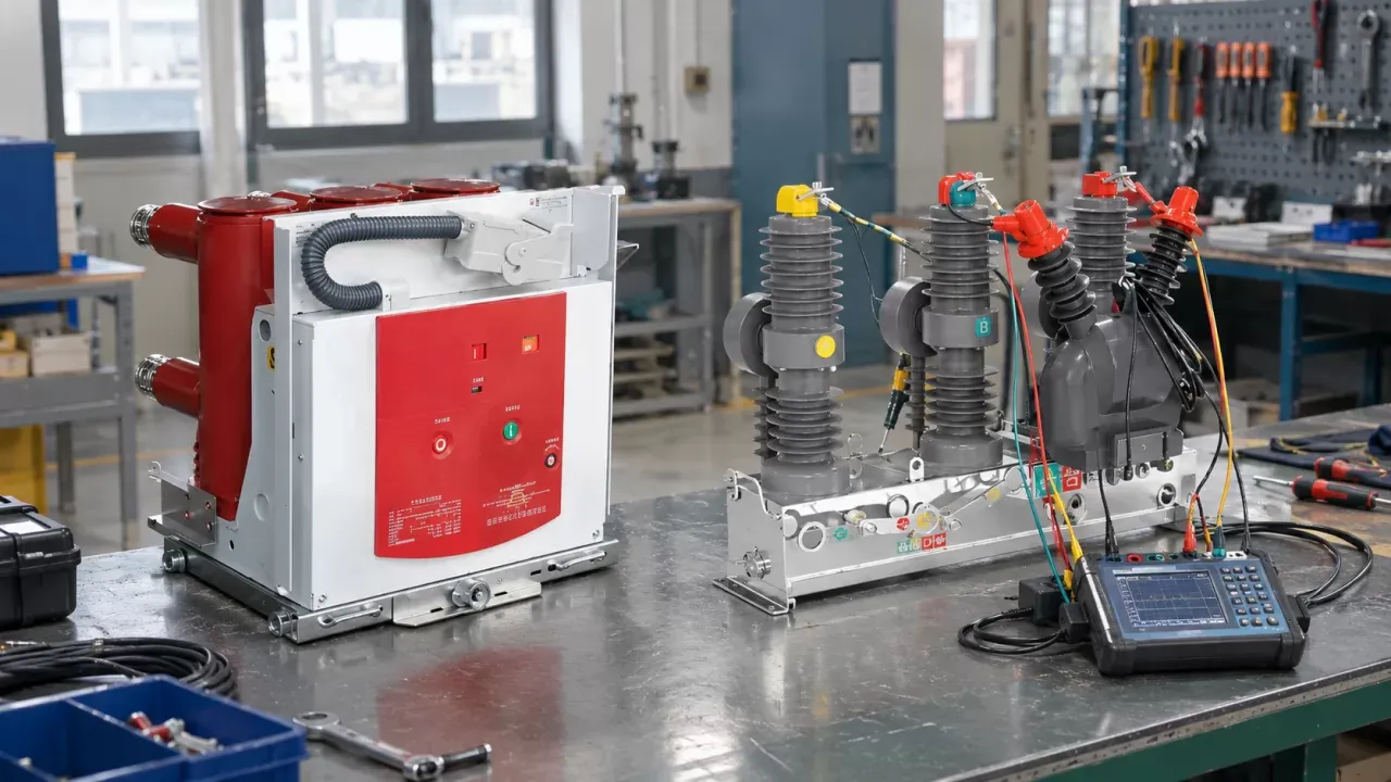
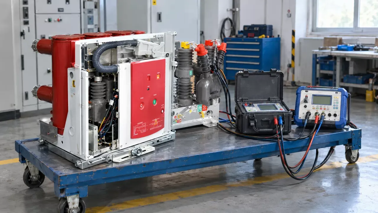
In the laboratory, breakers are proven by direct short-circuit testing, where a test station supplies both current and voltage, or by synthetic testing. In synthetic testing a high-current source drives the arc and a separate high-voltage circuit applies the TRV at current zero. Both methods record current, the voltage across the contacts and any breakdown at the same time, and they compare the measured TRV with the envelope required by the standard. Field verification follows the same idea on a smaller scale. A transient recorder or power-quality instrument with enough sampling rate and bandwidth, connected for the switching event, should capture phase currents and the voltages on both the source and load side of the open breaker. Record both sides of the open contacts. The trapped charge on the load side is often what is missing from the analysis, and without it a restrike can look like an unexplained source-side transient.
A trace that shows a breakdown is not enough to diagnose the cause. Read it together with the arcing time (a very short arcing time points to a gap that was still small), which pole cleared first, the measured contact travel and speed, and the condition of the interrupter. If a restrike happened on a breaker with good timing and good vacuum, look at the circuit. If it happened on one with slow travel, start with the mechanism.
Where the Two-Curve Model Stops Working
The race between recovery voltage and withstand describes typical AC interruption well. It depends on a natural current zero, and direct current has none. DC breakers have to create a zero, by commutating the current into a parallel path, by injecting a counter-current from a charged resonant circuit, or by building an arc voltage higher than the system voltage. The physics and the failure modes then change a great deal.
Even for AC, a single simplified curve is not enough to rate a product. Thermal recovery dominates in some gas breakers. Particle-driven late breakdown matters more in vacuum. At higher rated voltages, voltage grading across several gaps adds a further problem. The duty changes the picture again: fault clearing, capacitive switching and inductive switching each put the weak point in a different place. Use the model to see why a breakdown happened and what to check. Use type tests and system studies to decide whether a given breaker is suitable.
FAQ
What is the difference between reignition and restrike in a vacuum breaker?
The difference is timing. Reignition is a breakdown less than a quarter cycle after current zero, and restrike is a breakdown a quarter cycle or later. Restrike is the more dangerous of the two on capacitive duty, because the trapped charge and the opposite-polarity source voltage combine to produce higher overvoltages.
Does an aging vacuum interrupter restrike more easily?
Yes, it can. Contact erosion, a degrading vacuum and a slower mechanism all reduce dielectric recovery. Regular timing tests, contact wear checks and open-gap withstand tests show the decline before it causes a failure in service.
Can surge arresters stop a VCB from restriking?
No. Arresters limit the overvoltage that a restrike produces, but they do not stop the gap from breaking down. Preventing the breakdown takes a breaker with enough withstand margin for the duty, or a lower recovery voltage stress.
Is restrike a concern when switching motors or unloaded transformers?
It is less of a concern there. The main problem with these loads is current chopping and the fast overvoltages it causes, sometimes followed by multiple reignitions. RC snubbers or surge arresters near the load are usually the more relevant protection.
What does capacitive switching class C2 actually guarantee?
Class C2 guarantees a very low probability of restrike, demonstrated under the test duties defined in IEC 62271-100. It does not guarantee zero restrikes in service. Check that the tested bank current and the back-to-back inrush values on the type-test report match or exceed those of your installation.