The grid-tied inverter is specified, and the cable schedule is signed off, yet someone on the project still asks why the bill of materials includes a transformer. The isolation transformer for photovoltaic systems is the least interesting item in that BOM, and it is easy to under-specify. It is still worth getting right: it keeps PV-side faults off the grid, matches the inverter's output to the network voltage, and often decides whether the plant passes grid acceptance.
Galvanic isolation: DC leakage and high-voltage faults stay on the PV side, and enclosures stay dead.
Voltage matching: 690V/800V inverter output is converted to standard 380V/400V grid voltage.
Two-way protection: grid surges and harmonics are kept away from inverters and storage PCS.
Strongest fit: C&I rooftops, utility plants, agri- and fishery-PV, and PV-plus-storage.
Lock before RFQ: kVA, both voltages, vector group, losses, enclosure type and test reports.
What a well-isolated PV grid connection looks like in operation
A well-isolated PV grid connection puts no DC into the public network, has no live enclosures, and delivers voltage that matches the grid's nominal level. It also keeps a fault on one side from spreading to the other. The isolation transformer is the component that produces all four results. How much it matters depends on inverter design and local grid rules.
In operation, it looks like this. The primary winding takes the inverter's AC output. The secondary winding feeds the grid. The two windings have no conductive path between them; energy crosses only through the magnetic field in the core. Because of that, a DC fault, a ground leak on the array or an insulation failure in a combiner box has no copper path to the utility side.
The secondary voltage sits at the network's nominal level, so the protection relays and meters at the point of connection see the voltage they were set for. When lightning induces a surge on the distribution line, or a neighbouring industrial load pushes harmonics back up the feeder, the transformer's impedance absorbs part of the disturbance before it reaches the inverter's power electronics.
So is the isolation transformer essential? For many medium and large PV installations, it is. That applies wherever the inverter output voltage differs from the grid voltage, wherever the grid operator requires physical separation, and wherever the site conditions make leakage and PID likely. For small residential systems with certified transformerless inverters, it often is not.
Do grid-tied solar systems need an isolation transformer?
Grid-tied solar systems need an isolation transformer only in some cases. The deciding factors are the inverter topology, the gap between inverter output voltage and grid voltage, and the interconnection rules of the local utility. A certified transformerless inverter on a matching low-voltage grid can usually connect without one. High-voltage string or central inverters generally cannot.
The transformer is effectively mandatory in three situations. The first is an inverter whose AC output (690V or 800V is common on large string and central units) does not match a 380V/400V distribution grid. The second is a grid code or utility that explicitly requires galvanic separation at the point of connection. The third is a system design that relies on a functionally earthed DC side, which some thin-film and older module technologies call for.
It is optional when the inverter already outputs grid voltage, has its own residual current monitoring and DC-injection control, and the utility accepts transformerless designs. Many residential and small commercial systems fall into this group.
Leaving it out is a false saving in a third group of projects. These are sites with high humidity or standing water, large arrays where parasitic capacitance to earth adds up, and installations feeding sensitive industrial loads that cannot tolerate nuisance tripping from leakage current. In these cases the transformer costs less than the yield losses, residual-current trips and maintenance call-outs it prevents.
Before deciding, read the utility's interconnection agreement rather than the inverter brochure. The agreement is what the inspector checks.
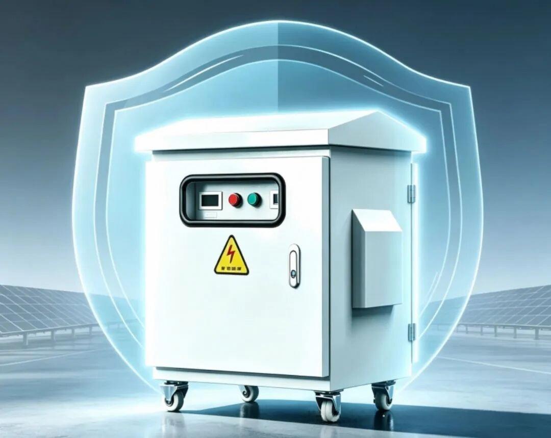
Galvanic isolation, leakage current and DC injection in plain terms
Grid codes, inverter datasheets and transformer quotes all use the same small set of terms, and suppliers do not always use them with the same meaning. These are the six that come up most often:
Galvanic isolation: no conductive path between two circuits; energy transfers only through magnetic coupling.
Leakage current: unwanted current flowing to earth through insulation, capacitance or damaged cabling.
DC injection: direct current component an inverter pushes into the AC grid, which utilities strictly limit.
Common-mode noise: high-frequency voltage appearing on all conductors relative to earth, driven by inverter switching.
Potential induced degradation (PID): power loss in modules caused by voltage stress between cells and the earthed frame.
Harmonic distortion: current or voltage at multiples of grid frequency, which heats equipment and disturbs protection.
One more term needs clearing up. A step-up transformer is a transformer that raises voltage, for example from low voltage to a medium-voltage collection grid. An isolation transformer can step voltage up, step it down or keep it at 1:1. In the PV setups discussed here it usually steps down. Inverter output at 690V or 800V is brought down to a 380V/400V network, and that is why "step-up" on a quote sometimes turns out to be an error that someone copied from a utility-scale template.
When a datasheet says "isolated", check which kind of isolation it means. A high-frequency transformer inside the inverter, a low-frequency transformer inside the inverter and a separate external isolation transformer give different levels of separation and have different consequences for earthing.
Voltage matching between 690V/800V inverters and 380V/400V grids
Large string and central inverters increasingly output at 690V or 800V AC. A higher AC voltage reduces current for the same power, which means smaller cables, lower resistive losses and fewer parallel runs between the inverter and the switchboard. Inverter makers design for these voltages because they are more efficient on the PV side.
Most factories, malls and office buildings, however, run on 380V or 400V three-phase, the standard civil and industrial voltage in IEC-based markets. The machines, lighting and switchgear on site are rated for it. The utility's meter and protection relays are set for it. An 800V output cannot be connected directly to that network.
The isolation transformer handles the conversion. Its turns ratio is designed for the specific input and output voltages, for example 800V primary to 400V secondary. The vector group sets the phase relationship and decides whether a neutral is available on the grid side. A delta primary with a star secondary and an accessible neutral is a common choice for low-voltage distribution, though the right configuration depends on the local earthing system.
A mismatch here fails in specific ways:
Wrong turns ratio: secondary voltage sits outside the utility's tolerance band, and the inverter trips on over- or under-voltage.
Wrong vector group: phase shift or neutral arrangement conflicts with existing site transformers or the earthing scheme.
No tap range: without off-circuit taps, the voltage cannot be adjusted when the actual grid voltage drifts from nominal.
None of these problems can be fixed on site. A transformer wound for the wrong ratio has to be rewound or replaced, and a custom unit can take weeks to remake. That is why voltage matching belongs in the first round of the specification and not in the commissioning checklist. Ask for taps of a few percent either side of nominal (the standard step size varies by market). They cost little and give the commissioning engineer room to adjust.
Solar inverter isolation transformer vs transformerless designs
Transformerless inverters have taken over the residential market and much of commercial PV, and there are good reasons for that. With no transformer core they are lighter, smaller and cheaper. They avoid the core and copper losses of a transformer stage, so their conversion efficiency is usually higher. For a rooftop system at the grid's own voltage, that efficiency gain adds up to real kWh over the system's life.
Removing the transformer also removes galvanic separation, and the design has to make up for it in other ways. Transformerless inverters rely on residual current monitoring, careful control of DC injection and insulation-resistance checks before start-up. The array is no longer floating independently of the grid. Its parasitic capacitance to earth, which grows with array size and with wet conditions, becomes a path for leakage current. On large or damp arrays this can trigger nuisance trips and makes certain module technologies more vulnerable to PID.
An external isolation transformer added to the inverter output gives the opposite set of trade-offs:
Yield: the transformer adds a small, permanent loss. No-load loss runs 24 hours a day, including at night when the array produces nothing, and load loss rises with output. A low-loss core and well-sized windings keep the loss small, but it never goes to zero.
Safety: physical separation means a PV-side insulation fault cannot energise grid-side equipment. Leakage paths through array capacitance are cut off at the transformer.
Earthing: the PV side can be earthed or floated independently of the grid's earthing system. Designers get more options, and coordination problems between the two systems are reduced.
Compliance: some utilities accept transformerless designs without question, some require separation above a set capacity, and some leave it to the inspector. An isolated design is rarely refused, while a transformerless one sometimes is.
Neither design wins outright. On small, dry, low-voltage systems, the transformerless design gives a better yield-to-cost ratio. On high-voltage inverters, wet sites, or grids with strict separation rules, the transformer usually pays for its losses through fewer trips, fewer insulation faults and an easier acceptance process. A sound choice compares annual transformer loss (in kWh, not efficiency percentage) with the downtime and service cost it avoids.
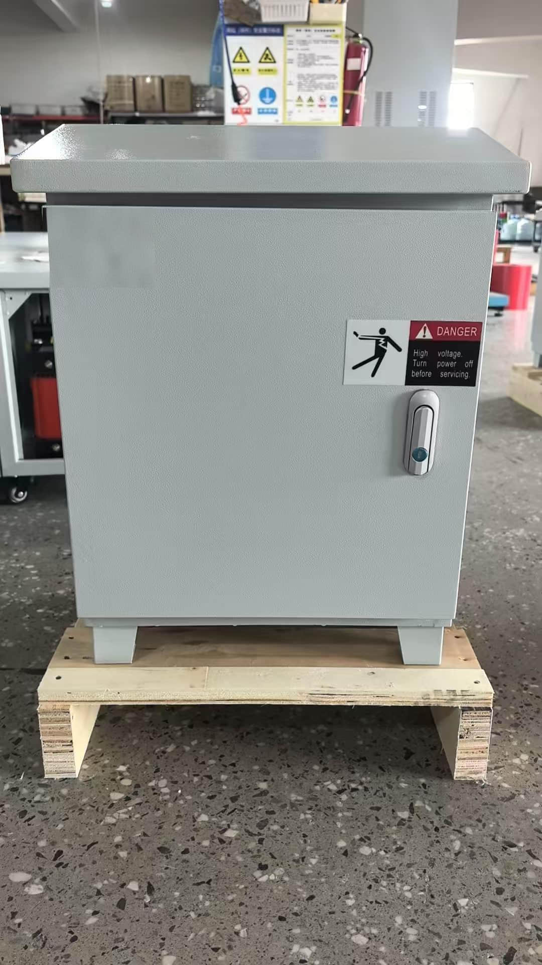
PV isolation transformer function and benefits across the system's lifespan
The usual argument for an isolation transformer is safety at commissioning. For a system expected to run for decades, the stronger argument is about yield and maintenance cost. Asking why to use an isolation transformer in solar PV is really asking what happens in years five, ten and fifteen, when insulation has aged, modules have taken years of voltage stress, and the grid has delivered thousands of switching surges.
Personnel and equipment safety
The primary and secondary windings are electrically separate. DC leakage on the PV side cannot reach the public grid, and a high-voltage fault upstream of the transformer cannot raise grid-side equipment to a dangerous potential. This is the basic protection against electric shock from touching an enclosure that should be dead.
The benefit grows as the plant ages. Cable insulation cracks, connectors corrode and junction boxes take in moisture. Each of these creates a possible leakage path. With galvanic separation in place, these defects stay local problems that maintenance staff can find and repair, rather than faults that put the grid side at risk.
Module degradation and yield
Every PV module has parasitic capacitance between its cells and its earthed frame. The inverter's high-frequency switching drives common-mode voltage across that capacitance, which produces leakage currents and voltage stress. In susceptible modules, sustained stress of this kind contributes to PID, a gradual loss of output that is often not noticed until a performance audit.
An isolation transformer suppresses common-mode noise between the inverter and the grid and allows more flexible earthing on the PV side. Both can help limit PID and protect long-term generation. It is one measure among several, alongside PID-resistant modules, correct DC-side earthing and, where needed, PID recovery equipment.
Protection from the grid side
Disturbances also travel from the grid toward the PV system. Lightning-induced surges, capacitor-bank switching and harmonics from neighbouring variable-speed drives all move up the feeder toward the inverter. The transformer's impedance blocks part of that energy before it reaches the semiconductors in the inverter or the storage power conversion system (PCS), the bidirectional converter that charges and discharges a battery.
The separation also limits how far a failure spreads. A fault on one side of the transformer does not bring down the whole system, so a grid-side event that would destroy an inverter in a directly coupled design often ends with a tripped breaker. Over the life of the plant, that is the difference between a reset visit and an inverter replacement.
Project scenarios where the transformer earns its place
The same component gets a different specification depending on where it is installed and what it feeds. Four scenarios cover most PV isolation transformer orders.
Commercial and industrial rooftops
Who uses it: factories, shopping malls and office buildings running self-consumption systems that export surplus power to the grid.
What they need: a step-down from high-voltage string inverter output to the building's 380V/400V distribution, with a neutral arrangement that matches the existing switchboard. Rooftop and plant-room space is often limited, so footprint and weight matter, as does access for forklifts or cranes.
What to look for: a vector group compatible with the building's main transformer, low no-load loss (the unit stays energised at night and on weekends), and an indoor enclosure with enough ventilation for the room. Plant rooms are often hotter than the design brief assumes.
A variation of this scenario is PV feeding workshop loads directly, where solar output supplies machine tools and production equipment on the factory floor. Isolation matters more here, because variable-speed drives and welding equipment produce harmonics. Ask for a transformer with harmonic losses taken into account in the design, which in North America is often specified through a K-factor rating.
Utility-scale ground plants and agri-/fishery-PV
Who uses it: EPCs and IPPs building centralised ground-mounted plants, and developers of agri-PV (panels above crops) and fishery-PV (panels above fish ponds or aquaculture water).
What they need: the transformer serves as the interconnection hub between the inverter blocks and the grid. It sits outdoors and is exposed to rain, condensation, dust and, at fishery sites, high humidity all year.
What to look for: a weatherproof outdoor enclosure with a rain hood, corrosion protection suited to the site (stainless steel or a properly prepared, powder-coated carbon steel), and anti-condensation measures such as space heaters or breather arrangements. For fishery-PV, confirm cable entry sealing and coating thickness; these are where corrosion tends to start.
PV-plus-storage and microgrids
Who uses it: sites combining PV with battery storage for peak shaving, backup or microgrid operation.
What they need: isolation of the battery's high-voltage side, so that a battery or PCS fault cannot spread into the microgrid and grid disturbances cannot reach the battery system. Microgrids also switch between grid-connected and islanded modes, and each transfer creates transients.
What to look for: a transformer rated for bidirectional power flow, since the PCS both imports and exports. Check inrush behaviour, because the transformer may be re-energised often during mode changes. Its impedance also needs to be coordinated with the PCS manufacturer's requirements. Some PCS units specify a minimum or maximum impedance, so get that figure from them before you send the RFQ.
Standards and certifications to confirm for your target market
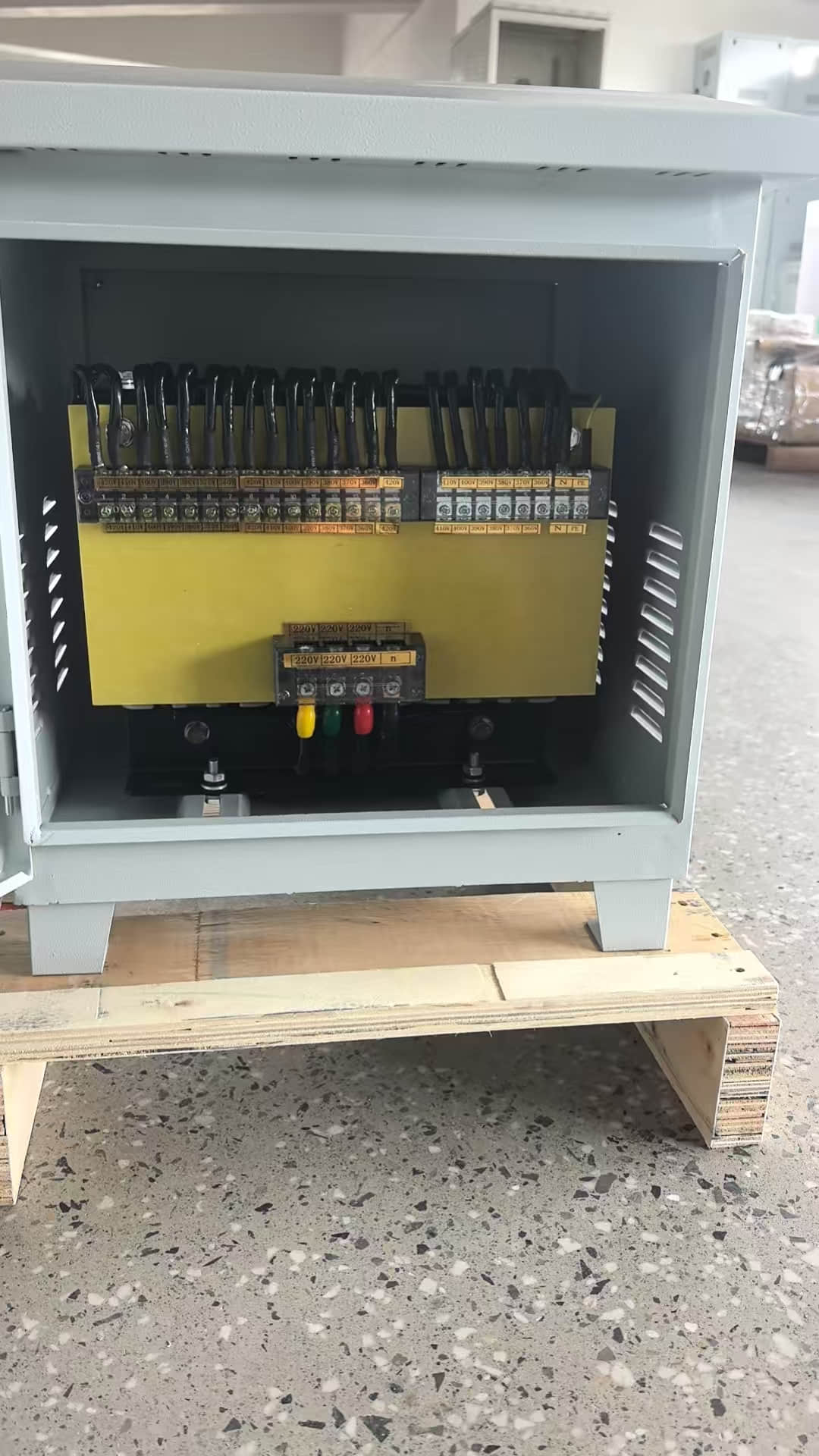
A transformer quote that says "meets IEC" leaves a lot unanswered. Three separate sets of rules apply to a PV isolation transformer installation, and you need evidence for each one.
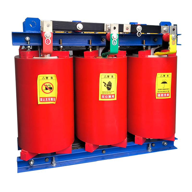
Transformer construction and testing. In IEC markets, the IEC 60076 series governs power transformers; IEC 60076-11 covers dry-type units specifically, including insulation, temperature rise and routine tests. Insulation class definitions come from IEC 60085, under which Class H corresponds to a 180°C thermal class. In North America the reference documents differ: UL 1561 for dry-type general purpose and power transformers, UL 1562 for dry-type distribution transformers above 600V, and the IEEE C57.12 family (notably IEEE C57.12.01 for dry-type general requirements). For US projects, check whether Department of Energy efficiency rules under 10 CFR Part 431 apply to the specific unit type and rating.
Enclosure rating. Outdoor cabinets in North America are usually specified to NEMA 250 Type 3R. This rating covers protection against rain, sleet, snow and external ice formation, but not windblown dust. If the site is very dusty, a Type 3R cabinet may not be enough on its own, so ask for a Type 3 or 4 rating or the IP-code equivalent under IEC 60529.
Interconnection. In the US, IEEE 1547 sets the requirements for interconnecting distributed energy resources with the grid, and inverters are typically listed to UL 1741. Elsewhere, the local grid code applies, along with the specific utility's connection agreement. These documents decide whether isolation is required, which DC-injection and leakage limits apply, and what protection must sit at the point of connection.
Ask the supplier for:
Type test reports for the design, issued by a named laboratory, matching the rating you are buying.
Routine test reports for each unit: winding resistance, ratio, no-load and load losses, applied and induced voltage.
Certification marks verifiable in the certifier's online directory (UL, CSA or ETL listings for North America), not only a logo on the nameplate.
Enclosure documentation stating the NEMA type or IP code and how it was verified.
Here is why "meets IEC" falls short in North America. Authorities having jurisdiction usually require a listing by a Nationally Recognized Testing Laboratory (NRTL), and an IEC test report does not provide one. A unit built to IEC 60076-11 may be electrically sound and still fail the US electrical inspection because it lacks the listing. Settle the target market's certification route before you compare prices.
How to choose an isolation transformer for photovoltaic systems
Work through the specification in order: electrical ratings first, then construction, then the environment the unit has to survive. Each step narrows down the next, and an early mistake is expensive to correct later.
Electrical ratings and configuration
kVA capacity with headroom: size above the inverter's maximum continuous AC output, not its nominal rating. Inverters can run above nominal under cool, bright conditions, and harmonics add heating. A transformer running at its limit on every sunny afternoon ages its insulation faster.
Voltages, vector group and losses: state the exact primary and secondary voltages, tap range, vector group and connection method (terminals, busbar or cable lugs). Ask for guaranteed no-load and load loss figures with test tolerances. PV transformers sit energised and lightly loaded for long periods (nights, cloudy days), so no-load loss affects lifetime energy cost more than the nameplate efficiency suggests.
Windings, core and insulation class
Winding conductor: copper windings are more compact for a given rating, conduct better and make more reliable terminations. Aluminium windings are lighter and cheaper but need a larger cross-section and careful joint design. Both can perform well, but the drawing must state which you are getting, along with the conductor size.
Core and insulation: the grade of the electrical silicon steel and the core construction decide no-load loss and audible noise. Class H insulation gives thermal margin for continuous operation in hot plant rooms and outdoor cabinets in summer. Check the rated temperature rise as well as the insulation class. A Class H unit designed for a lower temperature rise runs cooler and has more reserve.
Enclosure, protection and installation
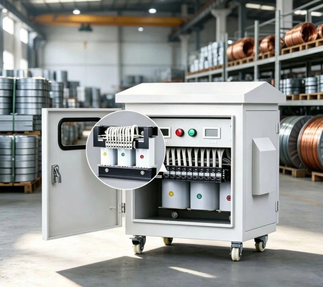
Outdoor siting: a NEMA 3R cabinet in powder-coated carbon steel suits most ground plants. Stainless steel is worth the extra cost at coastal, fishery-PV and chemically aggressive sites. Ask for an extended rain hood, lifting points and, where the unit may be moved during construction, heavy-duty casters with locks.
Indoor siting and controls: indoors, the priorities are ventilation, footprint and noise rather than weather sealing. In either location, check that leakage warning indicators, start/stop controls and clear warning labels are included, and confirm the earthing terminal location matches your drawings.
Rule of thumb: when two quotes differ only in price, compare their guaranteed loss figures over the plant's expected life before you look at the unit price again.
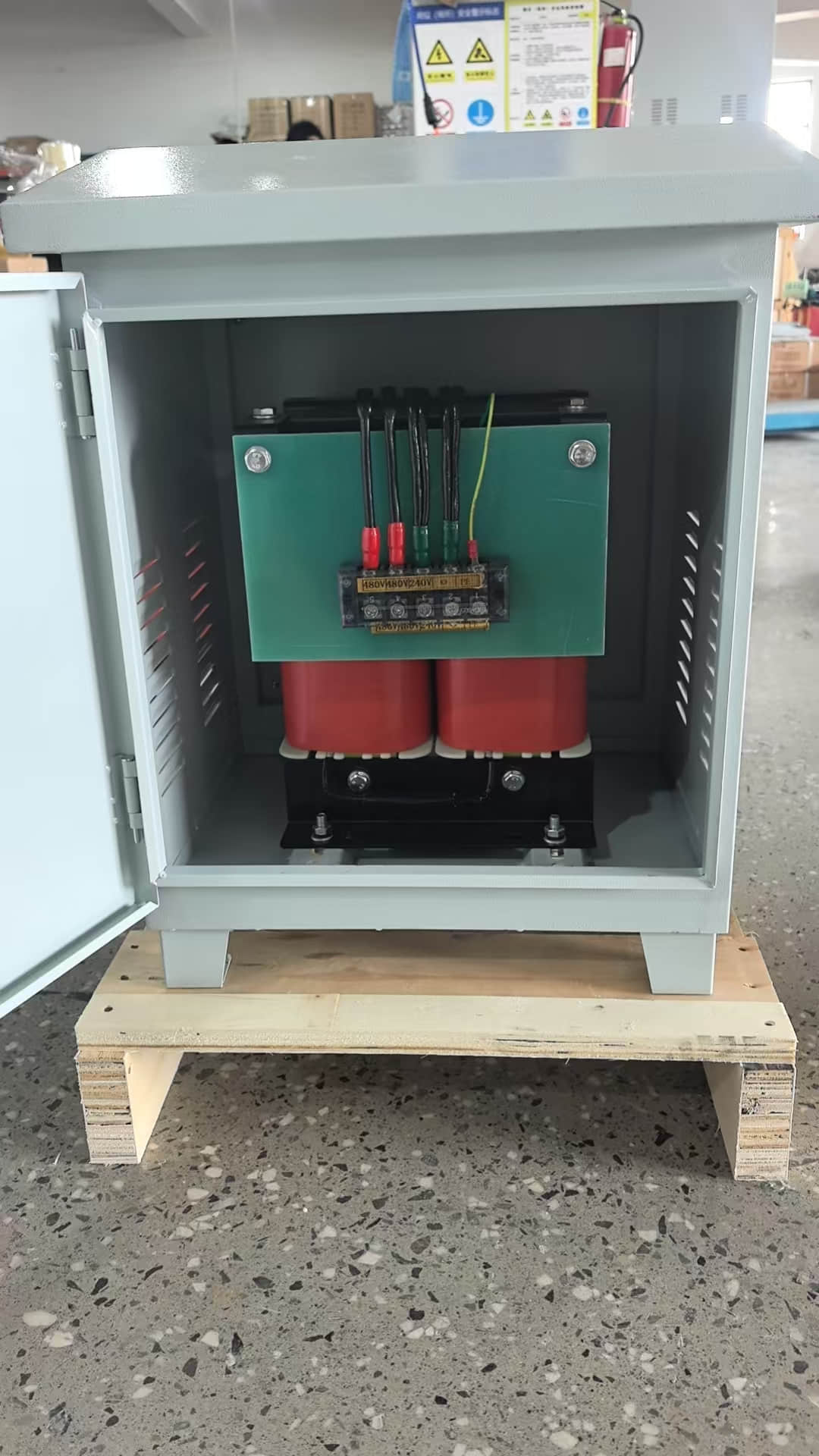
Sourcing pitfalls: custom builds, lead time and QC
Most PV isolation transformers are built to order, at least in part. Custom design solves voltage and space problems, and it also adds ways for the order to go wrong.
Approving a non-standard design without full drawings. A one-page datasheet does not count as a design approval. Ask for a general arrangement drawing, a wiring diagram, the nameplate layout and the conductor and core specifications before you release the PO. Mistakes found on paper cost nothing. Mistakes found at FAT cost weeks.
Choosing on unit price and ignoring losses. A cheaper core or a smaller conductor lowers the quote and raises the energy lost every hour the unit is energised. Write the guaranteed losses into the contract and agree a penalty or rejection rule if the routine tests exceed them.
Assuming stock units will fit a custom voltage. Units in stock ship quickly, but only at the voltages they were wound for. If your inverter outputs 800V and the stock unit's primary is 690V, quick delivery means nothing. Confirm the exact ratio before you count on a short lead time.
Leaving warranty and test terms undefined. Many suppliers offer a 2-year after-sales term. Check what it covers (parts, labour, on-site attendance), when it starts (shipment, delivery or commissioning) and who pays freight on returns. Name the routine test reports you expect with each unit in the RFQ, not after shipment.
Skipping pre-shipment inspection. Even an experienced factory benefits from a third-party or buyer-side check against the approved drawings: nameplate data, enclosure finish, terminal torque marks, packing for sea freight and moisture protection inside the crate.
The first spec to confirm before your next RFQ
Before you ask anyone for a price, get three facts in writing: the inverter's AC output voltage, the grid-side voltage at the point of connection, and the interconnection standard or utility rule the project must meet. Capacity margin, vector group, insulation class, enclosure type and certification route all follow from these three. A supplier quoting without them is guessing, and you will find out at commissioning which guesses were wrong.
Rule of thumb: confirm the two voltages and the grid rule first, and only then compare prices.
FAQ
Can a transformerless inverter connect to the grid without an isolation transformer?
Yes, often. If the inverter is certified for the local grid, outputs at grid voltage and has residual current monitoring, many utilities accept it without an external transformer. Large arrays, damp sites and grids with strict separation rules are the usual exceptions.
Does an isolation transformer reduce PV system efficiency?
Yes, slightly. Core loss runs whenever the unit is energised and copper loss rises with output, usually a low single-digit percentage of throughput depending on design and loading. Low-loss cores and correctly sized windings keep this small, and fewer trips and less degradation can more than make up for it.
Will an isolation transformer prevent PID on its own?
No. It suppresses common-mode noise and allows more flexible PV-side earthing, both of which can help limit PID. Module susceptibility, system voltage, humidity and DC-side earthing all matter, so treat the transformer as one measure among several.
What capacity margin should an isolation transformer have over the inverter rating?
Typically 10–25% above the inverter's maximum continuous AC output, depending on ambient temperature, harmonic content and future expansion plans. Hot plant rooms and sites with heavy non-linear loads justify the upper end of that range.
Is a dry-type isolation transformer suitable for humid fishery-PV sites?
Yes, if it is built for it. Specify Class H insulation, moisture-resistant winding treatment, a stainless steel or well-coated weatherproof enclosure with a rain hood, anti-condensation heating and sealed cable entries.