Short-circuit levels of 25 kA and 40 kA and a mandatory 30-year service life appear together in a Moldovan tender for 35, 110 and 330 kV substations. That tender specifies an inverted-type current transformer at every voltage level. The reasons, and the catches sellers rarely mention, follow the order in which you would make the decision.
The Inverted CT Puts Its Cores at Line Potential, Not at Ground
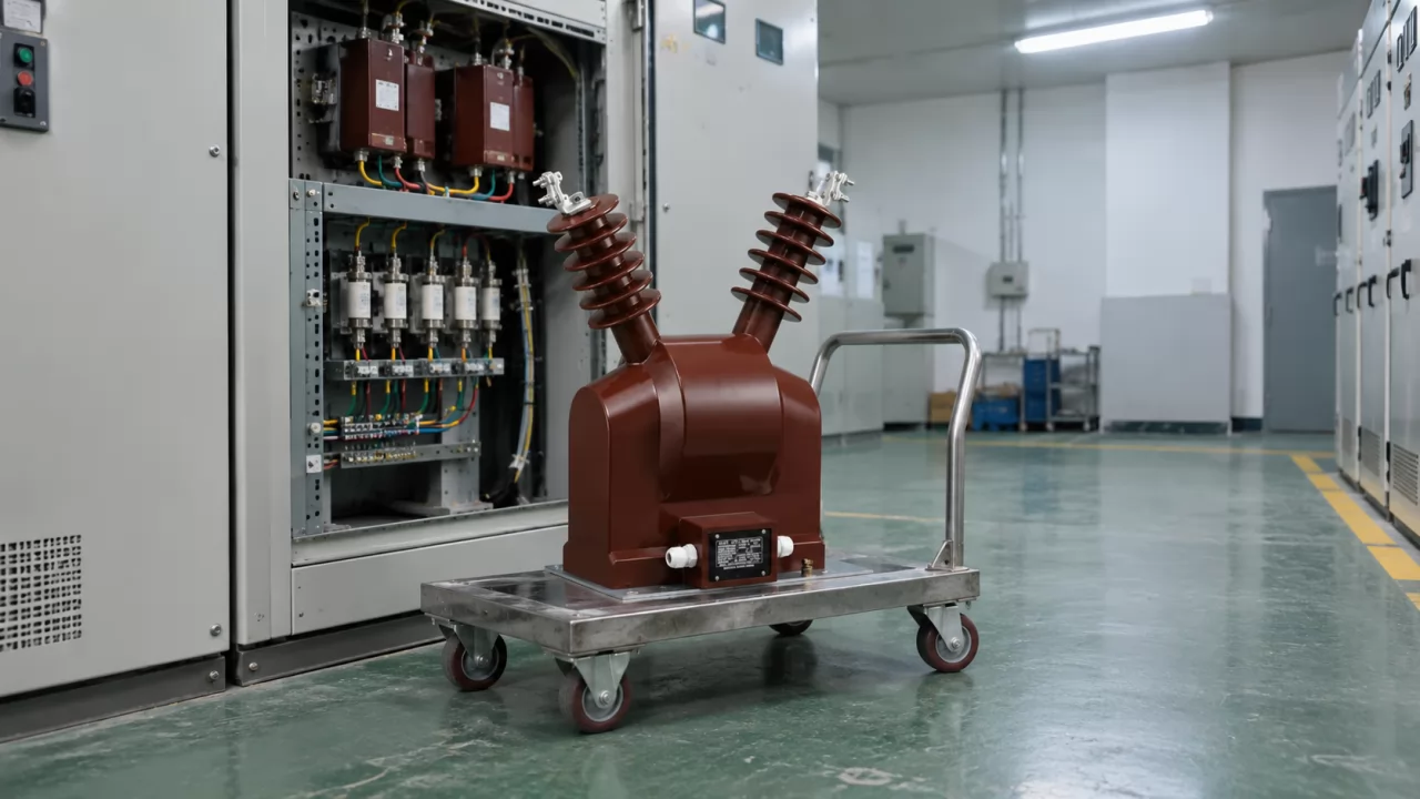
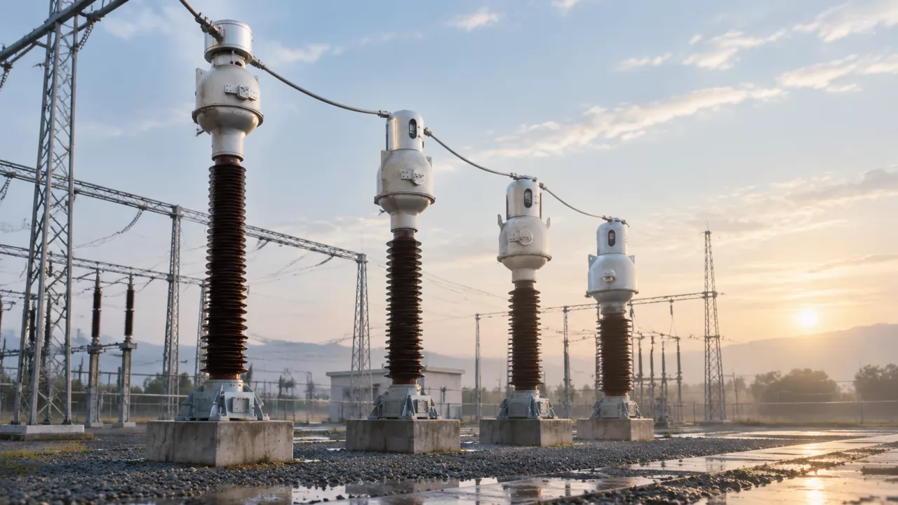
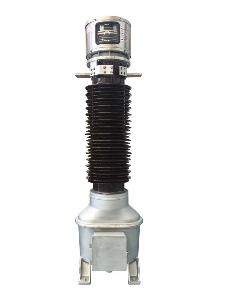
An inverted current transformer is an oil-immersed instrument transformer whose secondary windings and cores sit inside a metal head at the top of the unit. That head is energized at line voltage, a straight primary bar passes through the cores, and only the base is grounded. This layout suits high currents and high fault levels in open-air substations.
For an outdoor yard at 35 kV or above with heavy fault duty, the inverted live-tank design is usually the right default. That changes if the site has demanding seismic requirements, if the equipment sits inside gas-insulated switchgear or an indoor panel, or if fault levels are modest and price matters more than withstand margin.
The term "live tank" describes the head. Its metal housing sits at the system's high-voltage potential, so the whole top of the unit is energized. The upright design works the other way round. In an upright CT, the primary winding is in the head, and the cores and secondary windings sit in a grounded oil tank at the bottom. Engineers often call this the hairpin or dead-tank design because the primary conductor runs down into the tank in a U-shape and back up again.
The difference changes where the insulation goes. In an inverted CT, the main insulation is wrapped around the secondary winding housing in the head, not along a long primary conductor. The primary is short and straight, which helps at high current. The heavy, hand-built insulation sits at the top of a tall porcelain or composite column, which creates the risks covered later.
So before you compare prices, settle two questions: where the equipment will be installed, and how much current and fault energy it has to carry.
How Does an Inverted Current Transformer Work?
An inverted current transformer works like any current transformer. Primary current creates a magnetic flux in the cores, and that flux induces a proportional current in the secondary windings. What makes the live tank current transformer's working principle different is the geometry: a single straight primary turn, cores mounted at line potential, and insulation built around the windings.
A Straight Primary Bar Acts as a Single-Turn Winding
The primary conductor is a solid bar or tube that passes vertically through the center of the ring-shaped cores. Electrically, it is a one-turn primary winding. The ratio comes entirely from the number of secondary turns on each core.
A short, straight conductor has low resistance, so it generates less heat at rated current. It also has a short thermal path to the outside air through the head. At ratings around 2000 A or 4000 A, this keeps losses and temperature rise easier to control than in a conductor that has to bend down a long insulator and back. Fault behavior benefits too. A straight bar has no loop for electromagnetic forces to pull apart during a short circuit.
Capacitor-Graded Oil-Paper Insulation Carries the Voltage Down to Earth
The cores and secondary windings sit in a metal housing inside the head, and that housing has to stay close to earth potential because the secondary circuit is grounded. The main insulation is wrapped around the housing and around its supporting conduit. It consists of layers of oil-impregnated paper with conductive foils, called capacitor screens, inserted at set intervals.
The screens form a chain of capacitors in series. They divide the voltage between line potential at the outer shell and ground potential at the inner housing into controlled steps. A well-graded design keeps electric stress even through the wrap. That is why oil-paper capacitor insulation can reach low partial discharge levels when it is made correctly.
Secondary Leads Travel Down an Insulated Metal Conduit
The secondary connections cannot simply drop through the oil. They run inside a grounded metal conduit that leaves the bottom of the head housing and runs down the center of the insulator column. The capacitor insulation continues along this conduit, which is why the inside of an inverted CT looks like a bulb on a long stem. At the bottom, the leads end in a terminal box on the grounded base. There, the protection and metering circuits connect to the substation cabling.
Head, Insulator, Base: Each Section Has One Job
Reading a general arrangement drawing is much easier once you know what each part is for.
The head is a metal tank, often aluminum, that holds the cores, secondary windings, primary bar and most of the insulation wrap. It carries the primary terminals and is energized at line voltage. Because it holds the active parts, it is also where most of the weight is. On top or alongside sits the expansion compensator. This is usually a stainless-steel bellows or similar device that absorbs changes in oil volume as temperature changes, keeping the oil sealed from outside air. You should see an oil-level indicator and a temperature scale here. Many tenders, including the Moldovan one, make these mandatory.
The insulator is a hollow porcelain or composite (silicone rubber on a fiberglass tube) column. It provides the external creepage distance and contains the oil and the insulated secondary conduit. Porcelain has a long service record. Composite housings weigh less and do not shatter, which some utilities prefer for both seismic and safety reasons.
The base is grounded. It holds the secondary terminal box, the earthing connection, usually an oil drain or sampling valve, and the mounting points that attach the unit to its steel support structure.
These terms appear throughout tender documents and test reports:
Live tank — a design in which the metal housing of the active parts is energized at line voltage.
Dead tank — a design in which the housing of the active parts is grounded, with the high-voltage parts insulated from it.
Capacitor screen — a thin conductive foil placed between paper layers to divide the voltage across the insulation into even steps.
Partial discharge — small electrical discharges inside voids or defects in insulation, used as an early indicator of manufacturing flaws.
Short-time thermal current rating — the RMS fault current a CT can carry for a stated time, often one or three seconds, without overheating.
Dynamic and thermal stability — the CT's ability to survive the peak mechanical forces of the first fault cycle and the heat of the full fault duration.
The last two ratings are the ones to check most closely against your system study, because they rarely appear in headline specifications.
First Decision: Open-Air Yard, or GIS and Indoor Switchgear?
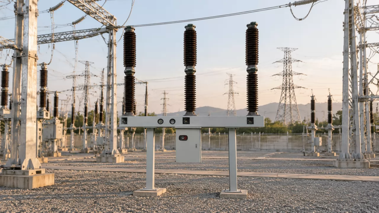
Live-tank inverted CTs are designed for outdoor air-insulated substations (AIS), where equipment stands in open air on steel structures and air provides the phase-to-phase and phase-to-ground clearances. The design is used from 35 kV up to 750 kV in that setting.
Inside gas-insulated switchgear (GIS), a different type of transformer is used. GIS current transformers are built into the switchgear enclosure, usually as ring cores around the conductor inside the SF6 compartment, and they come from the switchgear manufacturer as part of the bay. A freestanding oil-filled unit cannot be fitted inside a GIS bay.
Indoor medium-voltage switchgear also uses its own types: window (ring) CTs around a cable or busbar, or bushing-type CTs. A 35 kV indoor panel lineup will not have space for an outdoor oil-filled column, and it does not need one.
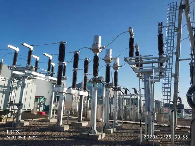
If your project is an AIS yard, keep reading. If it is GIS or an indoor switchroom, this product does not apply. Some hybrid sites combine an outdoor yard with indoor feeders. On those projects, check the single-line diagram so that every CT position is assigned to the correct type before you issue the RFQ.
Second Decision: High Primary Current and Fault Levels Favor the Inverted Design
Once the CT is confirmed as outdoor, the next question is how hard the circuit will push it. The inverted design's main strength is dynamic and thermal stability. The short straight primary has no loop for fault forces to deform, and the head conducts heat away well. This makes it comfortable at rated currents of 2000 A and 4000 A and at short-circuit levels of 25 kA, 40 kA and 63 kA. The Moldovan tender specifies 25 kA and 40 kA, within that range.
The grounding method of the system is not a limiting factor. The same tender uses inverted CTs on a 35 kV isolated-neutral system and on 110 kV and 330 kV effectively grounded systems. Isolated-neutral networks can see sustained phase-to-ground voltages close to line voltage during a ground fault. Effectively grounded systems produce higher ground-fault currents. The design handles both, provided the insulation level and the short-time current are specified correctly.
Where the argument for the inverted design is strong, and where it is weak:
A 4000 A bus coupler at 110 kV or 330 kV — high continuous current and full bus fault level make the straight primary and strong withstand a clear advantage.
A line bay close to a generating station — fault levels toward 40 kA or 63 kA put dynamic stability at the top of the specification, which favors the inverted design.
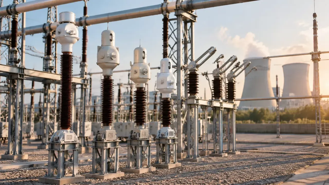
A 35 kV yard on an isolated-neutral network — moderate current, but tender rules often favor one CT design across all voltage levels for spare-parts and maintenance reasons.
A lightly loaded rural 35 kV feeder with a low fault level — the inverted design's advantages are less useful here, and a hairpin unit may be the more economical compliant offer.
The last case is a real decision point. If the tender does not specify the design, a hairpin offer at low current and low fault level can be technically valid. If the tender names the inverted design, as the Moldovan one does, an alternative design will usually be disqualified, whatever its price.
Inverted vs Hairpin Type Current Transformer: Where Each One Wins
Both designs are mature, and both are covered by IEC 61869-2, the international standard for current transformers. The choice depends on what your site needs most. Hitachi Energy's IMB series (originally developed by ABB) is a widely installed example of the oil-paper hairpin, tank-type design. Live-tank inverted units are made by several European and Asian manufacturers. The table sets out the differences that matter when comparing offers.
ITEM WHAT TO LOOK FOR
Core location and primary shape Inverted: cores in the energized head, straight single-turn primary. Hairpin: cores in the grounded bottom tank, U-shaped primary running down the insulator and back.
Short-circuit withstand and heat dissipation Inverted is generally stronger at high fault current and high rated current. Hairpin's longer primary carries more resistance and is exposed to more loop force under fault conditions.
Center of gravity and seismic behavior Inverted is top-heavy, with weaker seismic performance unless reinforced. Hairpin has its mass low in the tank and is usually more stable in earthquakes.
Oil volume Inverted holds relatively little oil, so the expansion compensator and level indication have to be reliable. Hairpin usually holds more oil, which buffers temperature swings.
Manufacturing difficulty Inverted needs hand-wrapped capacitor screens on the head assembly, a demanding process. Hairpin insulation is also skilled work but is applied along the primary conductor.
Transport and handling Inverted must be lifted and shipped strictly upright with reinforced bracing. Hairpin units also have handling rules, but their lower center of gravity is less sensitive to tilting.
Two other options are sometimes offered. SF6 gas-insulated current transformers, such as Trench's IOSK range, also use a top-core layout but replace oil and paper with pressurized SF6 gas. That removes oil-handling concerns but adds gas monitoring and, in the EU, F-gas regulatory issues. North American utilities have long used dead tank circuit breakers with bushing CTs mounted around the breaker bushings, which removes the need for freestanding CTs in many bays. Neither option is a direct substitute when a tender explicitly requires a freestanding oil-immersed inverted CT.
Oil-Immersed Inverted CTs in High-Voltage Substations: Three Typical Bays
The same basic product is specified quite differently depending on the bay. The three patterns below follow the voltage levels in the Moldovan tender and show what each bay asks of the CT.
35 kV Isolated-Neutral Feeder: Metering Plus Protection on Low Ratios
A 35 kV feeder typically carries modest load today and may grow later. The tender handles this with multi-ratio taps, such as 100-200/5 A. The secondary winding has an intermediate tap, so the CT can be reconnected from 100/5 to 200/5 at the terminal box without replacing it. For a distribution utility this saves a planned outage and a capital purchase when a new industrial customer or solar connection raises feeder load.
Check what happens to accuracy on the lower tap, though. A core sized for the full ratio performs differently on the reduced tap. Its accuracy-limit factor and rated burden on the 100/5 connection may be lower than on 200/5. Ask for accuracy and burden data for every tap position, not only the highest. On an isolated-neutral system, also confirm that the insulation level is specified for sustained high phase-to-ground voltage during a ground fault. Tender documents usually set this through the rated insulation level, and a compliant offer should state it explicitly.
The 5 A secondary is common at this voltage because 35 kV bays are often close to the control room and lead burden is easy to manage. At larger sites with long cable runs, 1 A secondaries are usually preferred, which is the choice the same tender makes at higher voltages.
110 kV Line Bay: High Fault Current Meets Revenue Metering
At 110 kV, two requirements meet in one unit. The tie-line or customer connection needs revenue-grade metering, and the bay must survive fault levels of 25 kA or 40 kA. The inverted head allows several cores to sit in one housing, so a single CT can carry a 0.2S metering core and several 5P protection cores together.
Class 0.2S under IEC 61869-2 is a metering class that keeps ratio error and phase displacement within tight limits across a wide current range, down to a small fraction of rated current. That matters on lines that spend long periods lightly loaded. Class 5P is a protection class. It keeps composite error within 5% up to the rated accuracy-limit factor, so distance or overcurrent relays see a true copy of the fault current.
These two core types have opposite design goals. A metering core should saturate early, protecting the meter during a fault. A protection core must not saturate until well into the fault range. Placing both in one head works because each core is a separate magnetic circuit on the same primary bar. Check that the offer confirms the instrument security factor for the metering core, as well as the accuracy-limit factor and rated burden for each protection core, at the stated short-time current.
330 kV Busbar Bay: Differential Protection Sets the Bar
Busbar differential protection compares currents entering and leaving the bus. Any mismatch between CTs looks like an internal fault, so the cores in each bay need to behave very similarly, especially when a through-fault drives them toward saturation. The Moldovan tender sets the mutual deviation between differential windings at ≤10%.
The inverted design makes that target easier to reach. Its secondary windings are shielded and have low leakage flux. The single straight primary passes symmetrically through the core center, so flux distribution around the ring is even and unit-to-unit variation is small. A hairpin primary, with its two conductor legs, can cause uneven flux distribution in the core, which makes matching harder.
Matching is a production-control issue as much as a design issue. Cores for differential windings should come from controlled material batches, and the routine test report should show the measured excitation characteristics for each unit. Ask for that data before shipment. Comparing curves from different cores on paper costs far less than tuning relays during commissioning.

Secondary Winding Count and Accuracy Class Drive Price More Than Voltage Alone
Two 330 kV CTs with the same ratio can differ in price by more than you would expect. In most cases the difference comes from the head.
The Moldovan tender calls for five- and six-winding configurations, which is typical for transmission bays. A common arrangement is one 0.2S metering core, one measurement core and three or four 5P protection cores serving line protection, backup protection and busbar differential. Tapped ratios such as 500-750-1500/1 A add further taps to each secondary. Each core adds iron, copper and a bigger winding window.
And the effect does not stop at the core. In an inverted CT, the capacitor insulation is wrapped around the secondary housing. A larger housing means a larger wrap, more paper and foil, more hand-wrapping time, a bigger and heavier head, more oil, and a stronger insulator to carry the load. Protection cores sized for high accuracy-limit factors at 40 kA are physically the largest. A single extra 5P core at a high burden can cost more than a step up in voltage class within the same frame.
When offers vary widely, compare core by core. Check rated burden, accuracy-limit factor and instrument security factor per winding. A low offer often turns out to have reduced burdens on the protection cores, which still meet the tender wording but give the relay engineer less margin. Also ask whether the stated tap ratios apply to every core or only some of them. In practice, specifying exactly the burdens your relays and cable runs need, rather than over-specifying every core "for safety", is often the biggest cost saving open to you, and it does not reduce reliability.
IEC 61869 Compliance and Tender Clauses You Must Answer Line by Line
Inverted CT tenders are usually evaluated as a compliance matrix, and a vague answer on one clause can cost the whole lot. The base reference is IEC 61869-1, which sets general requirements for instrument transformers, including insulation levels, partial discharge limits, temperature rise and mechanical requirements. IEC 61869-2 adds the current-transformer requirements: accuracy classes such as 0.2S and 5P, short-time current ratings, and routine and type tests. Partial discharge is measured according to IEC 60270. The insulating oil is normally specified to IEC 60296. For projects in North America, IEEE C57.13 replaces the IEC accuracy framework, and protection classes are written differently.
Three tender requirements need specific proof, not a "comply" tick.
The 30-year design life in the Moldovan tender is mandatory. Support it with your insulation design basis, gasket and bellows material data, and the service record of the same design.
Static mechanical terminal loads are 2000 N at 35 kV and 5000 N at 330 kV in that tender. These loads represent the pull of connected conductors and wind. A type test or calculation for the exact insulator and head combination being offered is the expected evidence.
The oil-preservation requirements (visible oil level, temperature scale and expansion compensator) are written as mandatory features. The drawing must show all three, and the material should state how the oil level can be read from ground level once the unit is installed.
Top-Heavy Mass, Hand-Wrapped Insulation and Small Oil Volume Are the Real Risks
Every advantage of the inverted design has a cost, and the costs fall mostly on the manufacturer's process and the logistics chain. Suppliers rarely put these in their brochures, so it helps to know them.
The first is weight distribution. Most of the mass is in the head, at the top of a tall insulator. That gives weaker seismic performance than a hairpin unit with its mass low in the tank. It also means the static terminal loads in the tender act on a structure that is already carrying a heavy top load. Projects in seismic regions often reference IEEE 693 (in North America) or a national seismic qualification standard. If yours does, require a seismic qualification report or a calculation for the exact configuration offered, including the support structure. A general statement does not prove compliance.
The second risk is workmanship. Capacitor screens in the head are wrapped by hand around an irregular shape, the secondary housing and its conduit. Misplaced foils, wrinkles, trapped air or insufficient drying and impregnation all cause partial discharge. A unit can pass the routine test and still have an insulation weakness that grows slowly over years. This is why the manufacturer's process control, including clean-room wrapping, vacuum drying times and impregnation records, matters as much as the test result.
The third is oil volume. Inverted CTs hold relatively little oil, so a given temperature change produces a larger proportional volume change, and the expansion compensator has to absorb it. A bellows that leaks or sticks can let moisture in or allow pressure to build up. That explains the tender requirement for a visible oil level and temperature scale: field staff need to check the oil-preservation system without equipment.
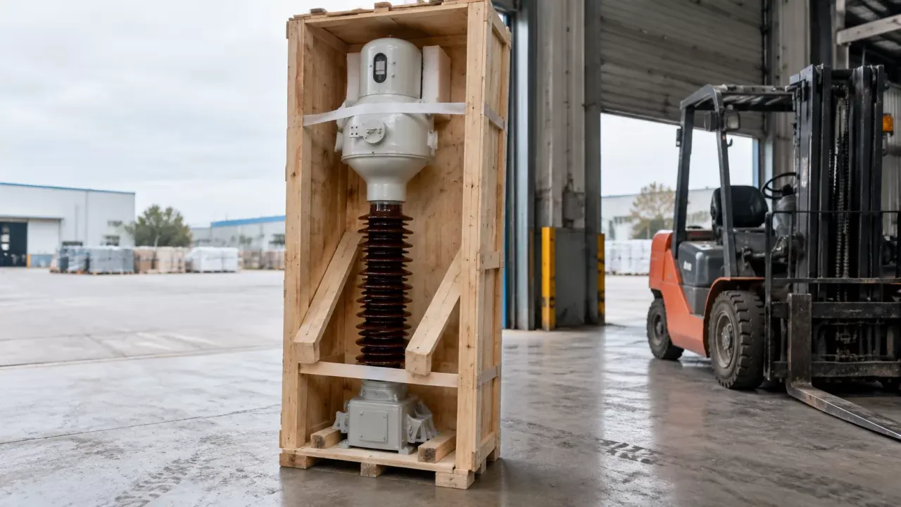
The fourth is transport. Units must be lifted and moved strictly upright. Tilting can move internal parts, stress the insulation or let air into the wrap. For sea freight this means custom crates braced against roll and pitch, a secured head, marked lifting points, and preferably tilt or shock indicators fitted to each crate so the receiving engineer can reject a damaged unit at the port, not after energization.
How to Choose an Inverted Type Current Transformer for Your Tender
The criterion that most often decides an evaluation is the electrical rating against your system study. Rated primary current and short-time thermal current, plus the peak dynamic current, must cover the bay's real fault level with margin. An offer that fails here is disqualified, regardless of price.
Next is the secondary package: number of windings, accuracy class and burden for each core, tap ratios, and, for busbar bays, proof that differential windings meet the matching requirement, such as the ≤10% mutual deviation in the Moldovan tender. This is where offers that look equal on paper usually begin to differ.
Third, check insulation quality evidence. Ask for partial discharge test reports from recent production of the same design, not only the type test, and include factory witnessing of routine tests in the contract. Witnessing the partial discharge measurement and the oil-level inspection costs little compared with replacing a failed 330 kV unit.
Fourth, look at mechanical proof: terminal load test or calculation for the offered configuration, and seismic data where the site requires it. Last, check the oil-preservation design and logistics plan, meaning the expansion compensator type, the level indication you can read from the ground, upright crate drawings and lifting instructions.
A rule of thumb: when two offers both meet the ratings, choose the one with the more detailed partial discharge and production records, because the hand-wrapped insulation in the head determines whether the unit lasts 30 years.
FAQ
Can an inverted CT be installed inside GIS or indoor switchgear?
No. It is designed for open-air substations. GIS uses built-in current transformers inside the gas enclosure, and indoor panels use window or bushing-type CTs.
Why is the head called "live" if the secondary circuit is grounded?
The metal head housing is at line potential. The capacitor-graded insulation inside it isolates the grounded secondary housing and conduit from that voltage.
Is an inverted CT better than a hairpin CT for busbar differential protection?
Usually, yes. Shielded secondary windings and the symmetrical straight primary keep leakage flux low, which makes tight matching between differential windings easier to achieve. Matching still depends on core material control in production, so ask for the excitation curves.
How should inverted CTs be packed for sea freight?
Strictly upright in braced crates, with the head secured against movement, lifting points marked, and tilt or shock indicators fitted so damage can be found on arrival.
If a unit passes the factory partial discharge test, can it still fail in service?
Yes. A passing routine test shows the insulation was acceptable on the day it was measured, not that every capacitor screen was wrapped and dried perfectly. Small defects can grow under years of voltage stress and temperature cycling. That is why production records and the service history of the design deserve as much attention as the test certificate.