In industrial power systems, few questions are as operationally important as this one: what is the maximum allowable temperature for dry-type transformers? The short answer is simple, but the safe engineering answer is not.
Most mainstream dry-type transformers use Class F insulation, with a maximum heat resistance of 155°C. However, that number is not a recommended normal operating target. In real plants, once temperature climbs into the 130°C to 140°C range, risk rises rapidly, insulation aging accelerates, and hidden internal damage may already be underway.
This is exactly where many factories make expensive mistakes. Operators see no smoke, no dripping oil, and no dramatic external warning, so they assume the unit is still safe. That assumption can destroy a transformer long before its expected design life.
This article explains the real dry-type transformer temperature rating, the maximum operating temperature dry-type transformer units can tolerate by insulation class, the transformer insulation class temperature limits that matter in the field, and the allowable temperature rise for dry-type transformers under actual operating conditions.
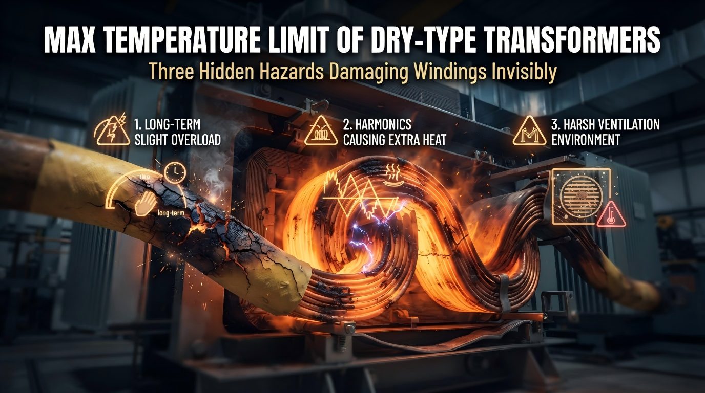
More importantly, it shows why overheating is often caused by a combination of mild long-term overload, harmonics, and poor ventilation—and why waiting for obvious symptoms can be disastrous.
A Dry-Type Transformer Hit 158°C in Under 5 Years: Why This Matters
A real factory case illustrates the danger clearly. A dry-type transformer that had been in service for less than five years suddenly reached 158°C on its temperature controller.
The site immediately started forced air cooling. The fans were running, but the temperature did not fall. Instead, it stayed dangerously high.
At that point, the correct decision was not “wait and observe.” The correct decision was emergency load shedding and partial shutdown.
That action caused a short production interruption and some temporary output loss. But it prevented a far larger loss: a transformer major repair or replacement costing hundreds of thousands in local currency, plus the possibility of fire, secondary switchgear damage, and extended production downtime.
Subsequent inspection found exactly what experienced power engineers fear in these cases:
Blackened iron core surfaces
Aged winding insulation
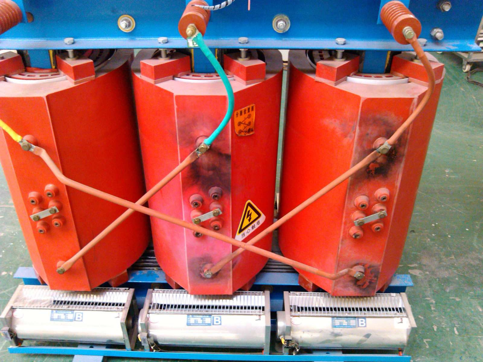
Clear thermal stress evidence inside the unit
The key lesson is critical. Unlike oil-filled transformers, dry-type transformers often do not provide dramatic external warning signs such as visible oil issues, heavy smoke, or obvious burnt smell before failure.
Once overheating passes a critical point, the unit can move quickly from “still operating” to internal short circuit or even fire. That hidden risk profile is why dry-type transformer overheating is frequently underestimated by operations teams.
What Is the Maximum Allowable Temperature for a Dry-Type Transformer?
The direct answer is this: for most mainstream dry-type transformers using Class F insulation, the maximum heat resistance is 155°C.
However, this value is often misunderstood. It does not mean a transformer should run at 155°C continuously. It means the insulation system is classified to withstand that thermal level under defined conditions.
In practical operation, a dry-type transformer should be kept well below that upper limit to preserve service life, ensure margin for hot-spot variation, and avoid sudden failure escalation.
For most plants, a practical rule is:
Below 110°C: generally acceptable if stable and verified
110°C to 130°C: increased attention required
130°C to 140°C: immediate inspection zone
Above 140°C: high-risk condition
Near or above 155°C for Class F: emergency response required
So when someone asks for the maximum operating temperature dry-type transformer units can handle, the correct engineering answer is twofold: the insulation class may define the theoretical ceiling, but safe continuous operation should remain significantly lower.
Dry-Type Transformer Temperature Rating by Insulation Class
To understand temperature limits correctly, operators must know the insulation class. The transformer insulation class temperature limits define how much thermal stress the insulation system can tolerate.
The most common insulation classes seen in dry-type units are Class B, Class F, and Class H.
Class B: maximum insulation temperature 130°C
Class F: maximum insulation temperature 155°C
Class H: maximum insulation temperature 180°C
In industrial distribution systems, Class F is widely used because it balances cost, performance, and thermal endurance. That is why many field discussions about dry-type transformer temperature rating center around the 155°C threshold.
Still, the insulation class is only one part of the picture. Real winding hot spots can exceed measured values. Ambient temperature matters. Ventilation quality matters. Harmonics matter. Even a transformer with Class H insulation can overheat prematurely if operating conditions are poor.
Allowable Temperature Rise for Dry-Type Transformers
Another common source of confusion is the difference between absolute temperature and temperature rise.
The allowable temperature rise for dry-type transformers is not the same as the total temperature displayed on the controller. Temperature rise refers to how much hotter the transformer becomes than the surrounding ambient air.
Three values must be distinguished:
1. Ambient temperature: the air temperature around the transformer, often assumed at 40°C in standard reference conditions
2. Average winding temperature: the bulk winding temperature under load
3. Winding hot-spot temperature: the hottest local point inside the winding, usually higher than the average and often higher than what the controller suggests
For example, if the electrical room is at 40°C and the transformer has an 80 K temperature rise, the winding average may reach about 120°C. The local hot spot may be even higher.
That is why operators should never treat a displayed temperature as the entire truth. Internal thermal gradients always exist.
Dry-Type Transformer Temperature Limits Table
| Insulation Class | Maximum Allowable Temperature | Typical Temperature Rise | Typical Ambient Reference | Practical Warning Threshold |
|---|---|---|---|---|
| Class B | 130°C | 80 K | 40°C | 110°C to 115°C |
| Class F | 155°C | 100 K | 40°C | 130°C to 140°C |
| Class H | 180°C | 125 K | 40°C | 150°C to 160°C |
This table should be used carefully. A “warning threshold” is not the same as a shutdown threshold, but it is the range where investigation must begin immediately.
In most industrial plants using Class F units, once the display approaches 130°C to 140°C, the transformer should be considered at elevated risk.
Why 130°C to 140°C Should Trigger Immediate Inspection
Many operators make a dangerous assumption: if the display is below the insulation class limit, the transformer is still fine. That is not how transformer heating works in real life.
When the temperature controller displays 130°C to 140°C, the actual winding hot spot may already be 10°C to 20°C higher. In other words, a displayed 138°C could mean an internal hot spot near or above the Class F limit.
That gap exists because sensors do not always sit at the hottest point. Heat distribution in windings is not uniform. Load imbalance, harmonic currents, duct blockage, and local airflow defects can create hidden internal hot spots.
Therefore, 130°C is not “normal fluctuation”. It is a serious warning band requiring immediate verification of:
Load rate
Harmonic distortion
Fan operation
Electrical room temperature
Air duct blockage
Why Dry-Type Transformer Overheating Is More Dangerous Than Many Operators Think
Dry-type transformers are often viewed as safer because they do not contain oil. That is true in one sense, but it can also create a false sense of security.
Oil-filled units often provide more visible distress clues. Dry-type units may continue operating while internal insulation carbonizes and winding damage progresses silently.
By the time external signs become obvious, the transformer may already be close to:
Insulation breakdown
Inter-turn short circuit
Phase-to-phase fault
Fire ignition inside the winding structure
That is why dry-type transformer overheating protection must be proactive, not reactive. Waiting for smoke is a bad strategy.
The 3 Biggest Causes of Dry-Type Transformer Overheating
Long-Term Mild Overload: The Most Common Silent Killer
The most common cause is not dramatic overload. It is the slow, deceptive pattern of operating at 90% to 100% load for long periods, with occasional slight excursions above rated capacity.
This is the electrical equivalent of “boiling a frog slowly.” The transformer does not trip. The alarm may not activate. Production continues. But heat accumulates day after day.
When a dry-type transformer runs for long periods at about 140°C to 150°C, insulation aging can roughly double in speed. A unit designed for around 20 years of service may lose effective life and fail in just 7 to 8 years.
This is not theory. It aligns with well-established thermal aging behavior in electrical insulation systems: every sustained increase in operating temperature significantly accelerates insulation deterioration.
Recommended field practice:
Measure transformer load rate every 6 months
If sustained load exceeds 80%, evaluate load transfer
If sustained load is near 90% or higher, plan capacity expansion or load redistribution
Harmonics: The Most Hidden Source of Extra Heat
The second major killer is harmonics, often the most underestimated source of overheating.
Modern plants increasingly use:
Variable frequency drives
UPS systems
Rectifiers
Welding equipment
EV charging infrastructure
These are nonlinear loads. They distort current waveforms and create harmonic currents that increase losses in the transformer.
The result is not just “a bit more heat.” Harmonics increase:
Core losses
Winding eddy current losses
Stray losses in structural parts
This means a transformer can overheat even when measured load rate is only around 70%. Operators look at kVA loading and think the transformer has margin, while internally the unit is being thermally stressed by waveform distortion.
The risk becomes worse when harmonics interact with capacitor banks. Harmonic resonance or oscillation can create extra heating in both the transformer and reactive power compensation equipment.
A practical engineering threshold is this: if total harmonic distortion (THD) exceeds 10%, corrective action is usually necessary.
Typical solutions include:
APF active power filters
Capacitor banks with series reactors
System harmonic study and tuning
Poor Ventilation in the Electrical Room
The third major cause is bad heat dissipation around the transformer.
A dry-type transformer depends heavily on surrounding air conditions. If the electrical room is too hot, airflow is blocked, or cooling fans fail, even a normally loaded unit can operate in a dangerous thermal environment.
The common high-risk conditions are:
Room temperature above 40°C
Blocked air inlets or outlets
Dust buildup in ventilation paths
Cooling fan failure
Forced-air system pulling in already hot air
In that situation, forced cooling may still be “running” but no longer effective. The transformer is basically sitting in a hot enclosed space, absorbing recirculated heat.
Recommended action:
Check electrical room temperature monthly
Strengthen ventilation when room temperature exceeds 35°C
Periodically test cooling fans and verify actual airflow
Keep all air paths clear of obstruction
Real-World Data: How Overload, Harmonics, and Ventilation Raise Temperature
The following field-style comparison shows how quickly temperature can rise under different operating conditions.
| Scenario | Load Rate | THD | Electrical Room Temperature | Cooling Condition | Observed Transformer Temperature | Risk Assessment |
|---|---|---|---|---|---|---|
| Normal operation | 65% | 4% | 28°C | Fans normal, ducts clear | 92°C to 102°C | Low |
| Mild long-term overload | 95% | 5% | 31°C | Fans normal | 128°C to 138°C | High |
| High harmonics | 72% | 14% | 30°C | Fans normal | 132°C to 145°C | High |
| Poor ventilation | 75% | 6% | 42°C | Air path blocked | 135°C to 148°C | Very high |
| Combined fault condition | 93% | 13% | 41°C | Weak exhaust, fan ineffective | 150°C to 158°C | Emergency |
These figures reflect what power engineers frequently observe in real industrial environments. Notice the key point: the unit does not need to be overloaded above 100% to become dangerously hot.
That is why looking only at apparent load is insufficient. Good overheating diagnosis always checks load, harmonics, and ventilation together.
Dry-Type Transformer Overheating Protection: What Operators Should Check First
When abnormal temperature appears, time matters. The first response should be disciplined and practical.
1. Review alarm records and trend data
Determine whether the rise was sudden or long-term. A gradual rise often points to overload or ventilation degradation. A sudden rise may indicate fan failure, ventilation blockage, or abnormal harmonic conditions.
2. Reduce load immediately if temperature is in the warning band
Do not wait for trip conditions. Partial load shedding can prevent insulation damage from escalating.
3. Verify cooling fan operation
Check not only whether fans are powered, but whether airflow is actually reaching the windings effectively.
4. Inspect room ventilation and air paths
Measure room temperature. Check louvers, exhaust systems, dust accumulation, and obstructions around the transformer.
5. Test harmonics
If nonlinear loads are present, conduct harmonic measurement. Do not assume normal loading means normal heating.
6. Inspect for discoloration, odor, and insulation distress
Even subtle signs matter in dry-type units.
This is the practical foundation of dry-type transformer overheating protection. Good response begins with fast triage, not guesswork.
Safe Temperature Thresholds for Daily Operation
Field teams need actionable bands, not abstract theory. The following ranges are practical for daily operation of a typical Class F dry-type transformer.
Below 110°C: generally stable if the trend is flat and room conditions are normal
110°C to 130°C: caution zone; verify load trend, harmonics, and ventilation
130°C to 140°C: high-risk warning; immediate inspection required
140°C to 155°C: severe overheating; prepare load reduction or shutdown
Above 155°C: emergency condition for typical Class F units
Temperature trend matters as much as absolute value. A unit at 128°C and climbing steadily is more dangerous than one at 132°C that briefly peaked and is clearly falling after intervention.
Recommended Operating Temperature Table for Dry-Type Transformers
| Displayed Temperature Range | Operating Condition | Risk Level | Recommended Action |
|---|---|---|---|
| < 110°C | Normal | Low | Continue monitoring and routine inspection |
| 110°C to 130°C | Elevated | Moderate | Check load rate, room temperature, fan status, and trend data |
| 130°C to 140°C | Abnormal warning | High | Inspect immediately; reduce load if needed; test harmonics |
| 140°C to 155°C | Dangerous overheating | Very high | Urgent intervention; reduce load aggressively; prepare shutdown |
| > 155°C | Critical for Class F | Extreme | Emergency shutdown unless engineering review proves safe temporary continuation |
How to Prevent Dry-Type Transformer Overheating Over the Long Term
Check Load Rate Every 6 Months
Every six months, perform an actual load survey. Do not rely only on nameplate assumptions or occasional operator observations.
If sustained load exceeds 80%, review the future growth trend. If the unit regularly approaches 90% to 100%, shift part of the load or uprate transformer capacity before overheating becomes chronic.
Test Harmonic Distortion and Mitigate When THD Exceeds 10%
Any facility with VFDs, UPS systems, chargers, or heavy nonlinear loads should treat harmonic testing as standard maintenance, not optional troubleshooting.
When THD exceeds 10%, typical corrective measures include APF active filters or capacitor banks with series reactors. In many real installations, 7% reactors are used effectively to suppress harmonic amplification.
Monitor Electrical Room Temperature Every Month
Electrical room temperature should be logged monthly, and more often during summer or peak production periods.
If room temperature exceeds 35°C, improve ventilation before the transformer reaches alarm levels. By the time the room crosses 40°C, transformer cooling margin may already be inadequate.
Take Temperature Controller Alarms Seriously
A display of 130°C to 140°C should never be dismissed as “temporary” without investigation.
Because internal hot spots may be 10°C to 20°C higher, this band can already represent dangerous thermal stress inside the winding.
Perform Annual Insulation Resistance Testing
At least once per year, test insulation resistance using a 2500 V megohmmeter. This is one of the most useful early warning methods for insulation aging.
A clear downward trend matters even if the value has not yet fallen below an absolute rejection threshold. Trend deterioration often appears before visible damage.
Measure Winding DC Resistance Every 2 Years
Every two years, measure winding DC resistance to detect hidden mechanical or electrical deterioration.
This test helps identify:
Broken conductor strands
Poor joints
Loose connections
Developing contact resistance problems
These defects can create localized heating that ordinary temperature observation may miss in the early stage.
Corrective Action Case: How One Factory Brought Temperature Back Below 110°C
In the earlier 158°C factory case, the overheating problem was not caused by a single issue. The transformer had all three major risk factors at the same time:
Long-term high loading
Excessive harmonics
Poor ventilation in the electrical room
The corrective solution worked because it addressed all three causes together.
1. Load redistribution
Part of the downstream load was transferred to another supply path, reducing the transformer’s continuous loading stress.
2. Installation of 7% reactors
This reduced harmonic impact and controlled the interaction between nonlinear loads and the capacitor compensation system.
3. Addition of strong exhaust ventilation
The electrical room received higher-capacity exhaust fans, improving air exchange and preventing hot air recirculation.
After these corrections, the transformer’s operating temperature stabilized at below 110°C.
This outcome is important. It proves that chronic overheating is often reversible if action is taken before catastrophic insulation breakdown. It also proves that solving only one factor is often not enough.
Experienced engineering teams and suppliers such as Weisho Electric understand that thermal problems in transformers must be evaluated as a system issue, not just a device issue.
Dry-Type Transformer Temperature Management Checklist
| Inspection Item | Recommended Frequency | Target / Threshold | Action if Abnormal |
|---|---|---|---|
| Load rate | Every 6 months | < 80% preferred for long-term reliability | Shift load or increase transformer capacity |
| Total harmonic distortion | Every 6 to 12 months, or after load changes | < 10% | Install APF or series reactors; perform harmonic study |
| Electrical room temperature | Monthly | < 35°C preferred | Improve ventilation or exhaust capacity |
| Cooling fan status | Monthly | All fans operating with effective airflow | Repair or replace failed fans; clear obstructions |
| Temperature controller alarm trend | Continuous/routine review | No persistent 130°C+ readings | Immediate inspection and load review |
| Insulation resistance | Annually | Stable trend, no obvious decline | Investigate insulation aging and moisture/thermal damage |
| Winding DC resistance | Every 2 years | Balanced and trend-stable | Check for broken strands, poor joints, bad contacts |
FAQ
What is the maximum operating temperature of a dry-type transformer?
It depends on insulation class. For mainstream Class F dry-type transformers, the insulation system maximum is typically 155°C. However, continuous operation near that limit greatly shortens service life, so real-world operation should stay well below it.
Is 130°C normal for a dry-type transformer?
No. For a typical Class F unit, 130°C is already a caution level that requires investigation. The actual internal winding hot spot may be 10°C to 20°C higher than the displayed value.
At what temperature should a dry-type transformer be shut down?
For typical Class F units, shutdown logic should be considered urgently when temperature approaches or exceeds 155°C, or when temperature continues rising despite forced cooling and load reduction. In practice, many engineers intervene well earlier if the trend enters the 140°C+ range and remains unstable.
What is the allowable temperature rise for dry-type transformers?
The allowable temperature rise for dry-type transformers depends on insulation class and design. Temperature rise is the difference between transformer temperature and ambient air, not the total displayed temperature. Typical designs may use around 80 K for Class B, 100 K for Class F, and 125 K for Class H, referenced to standard ambient conditions.
Can harmonics overheat a dry-type transformer even at low load?
Yes. Harmonics from nonlinear loads such as VFDs, UPS systems, and EV chargers can create extra core and winding losses, causing overheating even when transformer load is only around 70%. This is one of the most hidden overheating mechanisms in modern facilities.
How often should dry-type transformers be tested and inspected?
A practical schedule is: monthly checks for room temperature and fan status, every 6 months load-rate review, annual insulation resistance testing with a 2500 V megohmmeter, and every 2 years winding DC resistance testing. Harmonic testing should be done at least periodically and whenever nonlinear load conditions change.
Final Warning: If Temperature Exceeds 130°C, Treat It as a High-Risk Signal
The most important field rule is simple: if a dry-type transformer exceeds 130°C, do not normalize it.
At that point, three indicators must be checked immediately:
Load
Harmonics
Ventilation
Those three factors account for the overwhelming majority of serious overheating cases. If ignored, they can lead directly to insulation breakdown, winding damage, internal fault, and fire.
Factories that act early usually solve the problem with planned corrective work. Factories that delay often pay far more in transformer replacement, unplanned shutdown, lost production, and safety risk.
For operators, maintenance managers, and electrical engineers, the real takeaway is not just knowing the dry-type transformer temperature rating. It is understanding that the limit on paper is never the same as a safe long-term operating target.
That is why serious asset managers increasingly rely on structured thermal assessment, harmonic analysis, and preventive testing programs from experienced technical partners, including manufacturers and engineering teams such as Weisho Electric.
CTA: Need Help Assessing Dry-Type Transformer Overheating Risk?
If your dry-type transformer has reached 130°C or higher, if your plant runs heavy VFD or UPS loads, or if your electrical room regularly gets hot, do not wait for visible failure signs.
Review your transformer load rate, harmonic distortion, and ventilation conditions today. Check alarm trends. Measure room temperature. Test the fans. Verify whether your transformer is running near hidden thermal limits.
Act now before overheating turns into an outage, major repair, or fire. Bring in a qualified power engineer, conduct a proper thermal and harmonic assessment, and correct the root cause while the transformer is still recoverable.
Your next decision can be the difference between a controlled maintenance stop and a costly emergency shutdown.