Why This Overlooked Component Can Shut Down an Entire Production Line
In industrial electrical systems, a single misapplied device can halt operations for hours, costing tens of thousands of dollars per incident. The control transformer remains one of the most underestimated yet mission-critical components in any panel. Its job is deceptively simple: step down facility-level voltage to the lower levels that relays, contactors, PLCs, and solenoids need to operate safely.
Yet improper selection, sizing, or wiring of these devices accounts for a disproportionate share of nuisance faults in manufacturing environments. This guide delivers the technical depth that engineers, electricians, and facility managers need to get selection right the first time — protecting equipment, ensuring code compliance, and maximizing operational uptime.
How These Step-Down Devices Work in Control Circuits
Basic Operating Principle
These devices operate on electromagnetic induction. A primary winding receives a high-voltage supply from the facility bus, and through a precisely calculated turns ratio, the secondary winding outputs a lower voltage suitable for control-circuit components. Unlike general-purpose step-down transformers, units designed for control applications are engineered to withstand severe inrush current demands.
When a sealed contactor or solenoid first energizes, it can draw 10× its steady-state current for the first half-cycle. A properly rated unit handles this momentary surge without excessive voltage drop on the secondary, keeping all parallel devices operating within their specified voltage range.
Key Characteristics That Set Them Apart
VA (volt-ampere) ratings define the continuous power delivery capacity. Equally important is the regulation percentage — the difference between no-load and full-load secondary voltage. Tighter regulation (lower percentage) means more stable output under varying loads, which is critical for sensitive PLC inputs and timing circuits.
Compared with general-purpose machine-tool transformers, control-circuit-specific units feature heavier secondary conductors and core designs optimized for cyclic high-inrush duty rather than for steady-state resistive loads.
Common Voltage Configurations and Industry Applications
Standard Voltage Combinations
| Primary Voltage | Secondary Voltage | Typical Application |
|---|---|---|
| 480V | 120V | Industrial motor control centers |
| 480V | 24V | PLC and sensor circuits |
| 240V | 120V | Commercial HVAC panels |
| 600V | 120V | Heavy industrial (Canadian/some US) |
| 208V | 24V | Building automation systems |
Industry-Specific Use Cases
Manufacturing: CNC machines, conveyor systems, and robotic cells rely on these devices to power their control logic independently from high-voltage motor circuits.
HVAC: A control transformer for HVAC applications typically delivers 24V at 40VA–100VA to power thermostats, zone dampers, and gas valve circuits.
Water and Wastewater: Pump control panels and telemetry circuits in remote lift stations depend on reliable voltage conversion for continuous monitoring.
Oil and Gas: Hazardous location panels incorporate these units within motor starters to power a control circuit transformer feeding intrinsically safe barriers.

Sizing: How to Calculate VA Requirements Correctly
Step-by-Step Sizing Method
Proper sizing is the single most important decision in specifying these devices. The process requires identifying every connected load and accounting for worst-case inrush conditions:
1. List all connected devices — contactors, relays, indicators, solenoids, timers.
2. Record the sealed (continuous) VA for each device.
3. Record the inrush VA for each inductive load.
4. Apply the formula: Required VA = Inrush VA (largest single device) + Sealed VA (all remaining devices).
5. Add a 25% safety margin for future panel expansion.
Worked Example Using a Sizing Calculator Approach
Consider a typical motor control panel. A control transformer sizing calculator approach helps systematize the process:
| Device | Qty | Sealed VA (each) | Inrush VA (each) |
|---|---|---|---|
| NEMA Size 1 Contactor | 3 | 15 | 150 |
| NEMA Size 2 Contactor | 1 | 25 | 250 |
| Pilot Lights (LED) | 6 | 3 | 3 |
| Control Relay | 4 | 5 | 35 |
| Timer | 2 | 8 | 8 |
Calculation: The worst-case scenario assumes the largest inrush device (NEMA Size 2 contactor at 250VA) energizes while all other devices are sealed. Total = 250 + (3×15) + (6×3) + (4×5) + (2×8) + 0 (Size 2 sealed omitted since it is the inrush device) = 250 + 45 + 18 + 20 + 16 = 349VA. Adding 25% margin yields 436VA. Select the next standard size: 500VA.
Common Sizing Mistakes
Ignoring inrush: Sizing only for sealed current leads to chronic undervoltage during energization events.
Excessive oversizing: An oversized unit costs more, takes more panel space, and paradoxically offers poorer regulation at light loads.
Forgetting future loads: Panels accumulate devices over time; today's perfectly sized unit becomes tomorrow's bottleneck without adequate margin.
Wiring and Installation Best Practices
Standard Wiring Configuration
Understanding a control transformer wiring diagram is essential for correct installation. Primary terminals are designated H1–H4, while secondary terminals are X1–X2. Dual-primary units offer versatility: connect H1–H2 and H3–H4 in series for 480V input, or in parallel for 240V input.
Additive polarity (standard for units under 200kVA) means voltage adds across series-connected windings. Always verify terminal markings against the manufacturer's specific diagram before energizing.
Grounding the Secondary
Per NEC Article 250.30, a separately derived system — which these devices create — requires a grounding electrode conductor connection. Typically, the X2 terminal is bonded to ground. Floating (ungrounded) secondaries are permitted in specific applications but require ground-fault detection systems to remain code-compliant.
Overcurrent Protection
NEC Article 450.3 governs primary overcurrent protection. For units rated 600V or less, primary fuses are typically sized at 125% of rated primary current. Secondary fuses, per NEC 430.72, protect the control circuit downstream. Balancing protection sensitivity with nuisance trip avoidance requires understanding the inrush characteristics of connected loads.
Field-Proven Wiring Tips
Size secondary conductors to minimize voltage drop, especially on runs exceeding 15 meters.
Use ring terminals with appropriate torque (per manufacturer specs) to resist vibration loosening.
Route control wiring separately from power conductors to reduce electromagnetic interference.
Label all tap connections clearly for future maintenance personnel.

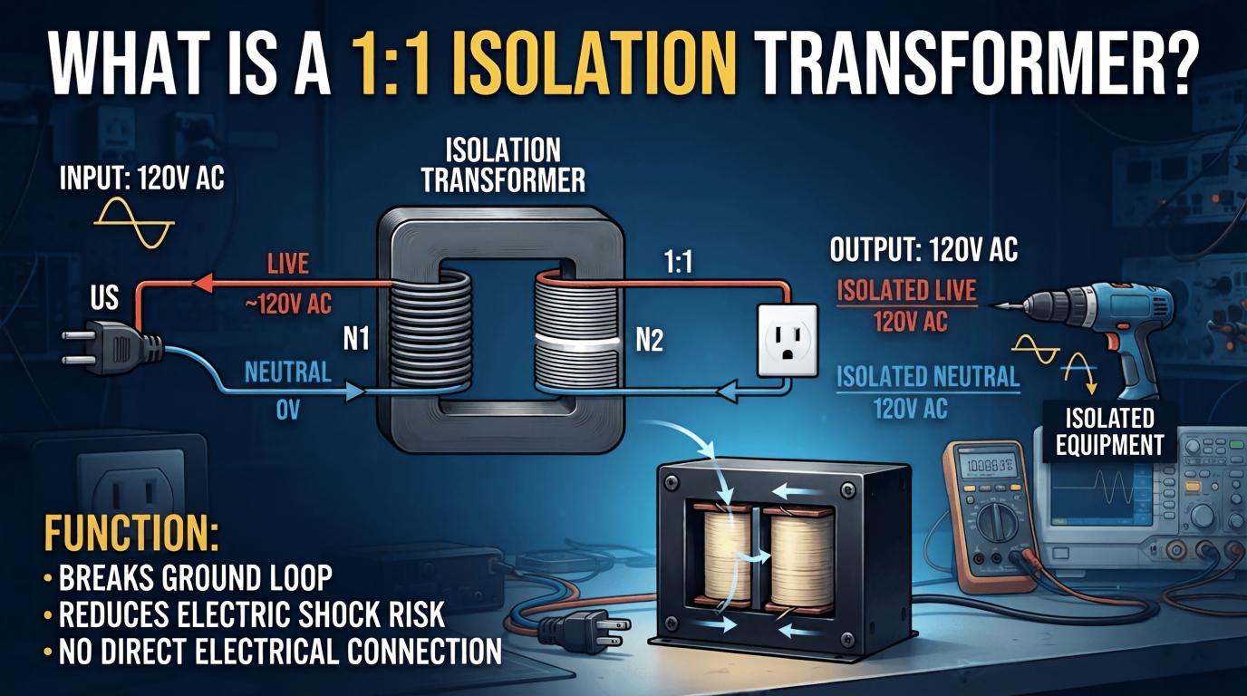
Comparison: Control Transformer vs. Isolation Transformer
These two device types serve fundamentally different purposes, though confusion between them is common. Here is how they compare across critical parameters:
| Feature | Control-Circuit Unit | Isolation Transformer |
|---|---|---|
| Primary Purpose | Voltage step-down for control circuits | Electrical isolation between circuits |
| Turns Ratio | Typically high (e.g., 4:1) | Often 1:1 |
| Inrush Handling | Optimized for high momentary loads | Not specifically optimized |
| Shielding | Basic or none | Electrostatic (Faraday) shield common |
| Typical Use | Motor starters, HVAC panels | Sensitive electronics, medical equipment |
| Regulation | 5–10% typical | Varies; often tighter |
| Relative Cost | Lower | Higher for equivalent VA |
Understanding the distinction between a control transformer vs isolation transformer is essential for specifiers. When both step-down and noise rejection are needed — such as PLC environments near variable frequency drives — some engineers deploy an isolation unit upstream feeding a dedicated control-circuit device downstream.
The 480V to 120V Configuration: Why It Dominates Industrial Plants
US industrial facilities predominantly distribute power at 480V three-phase. Since control devices (pilot lights, pushbuttons, contactors) are standardized at 120V, the control transformer 480V to 120V configuration is by far the most commonly specified unit in North American manufacturing.
Tapping a single phase from the 480V bus and converting it locally within each panel eliminates the cost and complexity of running a dedicated 120V feeder. For a typical 20-panel motor control center, this approach saves thousands of dollars in copper, conduit, and breaker space.
Selection Criteria
VA ratings range from 50VA (single-contactor panels) to 15kVA (large integrated systems).
Basic Impulse Level (BIL) ratings ensure the survival of voltage transients on the 480V bus.
UL 5085 and CSA C22.2 No. 66 listings are mandatory for code compliance in US and Canadian installations.
Enclosure options include open-core (panel-mounted), enclosed (standalone), and DIN-rail (compact units under 250VA).
Performance Expectations
Modern units in this voltage class achieve 92–97% efficiency at 50–100% load. With Class F or Class H insulation, temperature rise remains within safe limits even at continuous full-load operation. Expected service life under normal industrial conditions exceeds 25 years — making these among the longest-lived components in any electrical panel.
Case Study: Failure Analysis in an Automotive Assembly Plant
Background
A Tier 1 automotive parts manufacturer in Michigan experienced repeated PLC faults and contactor drop-out on a welding robot cell. The PLC was replaced twice at $8,000 per unit, and production losses during troubleshooting exceeded $30,000 before the true root cause was identified.
Root Cause Analysis
Investigation revealed an undersized 150VA unit feeding a panel with six NEMA Size 1 contactors. During shift startup, simultaneous energization caused secondary voltage to sag below 85V — well under the 90V minimum for reliable contactor holding. The problem was compounded by a 40°C ambient temperature, which derated the unit's effective capacity by approximately 15%.
Solution and Results
The engineering team resized to a 500VA unit based on proper inrush calculation methodology. They also implemented time-delay sequencing to prevent simultaneous contactor energization during startup. The results were immediate: zero control-circuit faults over 18+ months of continuous operation. The $200 upgrade investment prevented an estimated $45,000 in additional downtime costs.
Key takeaway: A component costing less than a restaurant meal prevented repeated five-figure downtime events. Environmental derating and inrush calculations are never optional.

Selecting the Right Industrial Voltage Transformer: Specification Checklist
Critical Parameters
VA rating matched to calculated load plus 25% expansion margin.
Primary and secondary voltages with available tap options.
Regulation percentage — lower is better for sensitive control logic.
Frequency rating (50Hz or 60Hz — affects core sizing and losses).
Mounting style: chassis, panel-mount, or DIN rail for compact units.
Agency listings: UL 5085, CSA, CE as required by jurisdiction.
Environmental and Mechanical Considerations
Operating temperature range and insulation class directly affect derating. Above 1,000m (3,300 ft) elevation, reduced air density impairs cooling — apply altitude derating factors per NEMA ST-1 guidelines. For mobile equipment or installations near heavy presses, specify units rated for elevated vibration and mechanical shock.
Applicable Standards
| Standard | Scope | Region |
|---|---|---|
| UL 5085 | Low-Voltage Transformers | North America |
| NEMA ST-1 | Specialty Transformers | North America |
| IEC 61558 | Safety of Power Transformers | International |
| NEC Articles 450, 725 | Installation Requirements | United States |
| CSA C22.2 No. 66 | Specialty Transformers | Canada |
Maintenance and Troubleshooting
Preventive Maintenance Schedule
Quarterly: Visual inspection of connections, signs of discoloration, and debris accumulation.
Annually: Infrared thermography scan to identify hot spots before they cause failures.
Every 3–5 years: Insulation resistance testing (megger) to assess winding integrity.
Ongoing: Load measurements to detect creeping overload from incremental panel additions.
Common Failure Modes
Overheating ranks as the primary failure mechanism — typically caused by sustained overload or restricted ventilation. Insulation breakdown from moisture ingress follows closely, especially in outdoor or washdown environments. Loose connections create localized hot spots that accelerate insulation degradation in a destructive feedback loop.
Troubleshooting Approach
1. No secondary voltage: Check primary fuses or breaker; verify supply voltage is present and within tolerance.
2. Low secondary voltage under load: Measure with full load energized; investigate overload condition, high primary-side impedance, or deteriorated connections.
3. Intermittent faults: Suspect inrush-related voltage sag, thermal cycling effects, or vibration-loosened terminals. Infrared scanning during operation can reveal the root cause.

Frequently Asked Questions
What size unit do I need for my application?
Sum the sealed VA of all connected devices, identify the highest single inrush load, then add the sealed VA of all remaining devices to that inrush value. Choose the next standard VA rating above this total, and add 25% margin for future growth. For complex panels with multiple large inductive loads, consider whether simultaneous energization is possible and size accordingly.
Can I use a step-down device designed for control circuits as an isolation transformer?
These devices do provide galvanic separation between primary and secondary windings. However, they lack the electrostatic shielding, tight regulation, and low-leakage design that purpose-built isolation units provide. For simple control-circuit isolation needs, they are adequate. For noise-critical electronics or patient-connected medical equipment, a dedicated isolation unit is required.
Why does my unit hum loudly?
Some audible hum is inherent — it results from magnetostriction in the iron core laminations at line frequency. Excessive or increasing hum can indicate loose laminations, overloading beyond nameplate rating, DC offset on the supply (common near VFDs), or mounting resonance. Check load current against the nameplate, verify mounting bolts are tight, and inspect for physical damage to the core structure.
How do I wire a dual-primary unit for different input voltages?
For 480V: connect H1 and H4 to the line, with a jumper from H2 to H3 (series configuration). For 240V: jumper H1 to H3 and H2 to H4, then connect the line across the H1–H2 terminal pair (parallel configuration). Always confirm with the manufacturer's specific wiring documentation for your unit, as terminal designations can vary between brands.
What is the difference between these devices and buck-boost transformers?
Units designed for control circuits handle high inrush loads and provide significant voltage reduction (e.g., 480V to 120V) with full isolation between windings. Buck-boost transformers make small voltage corrections (±5–20%) and are typically connected as autotransformers — meaning they share a common winding and provide no isolation. They serve fundamentally different purposes and are not interchangeable.
Conclusion: The Smartest Investment in Panel Reliability
Proper specification and installation of industrial voltage conversion devices directly impact uptime, safety, and total cost of ownership. As the automotive plant case study demonstrated, a correctly matched unit costing under $300 can prevent tens of thousands of dollars in unplanned downtime. The cheapest option is never the one with the lowest price tag — it is the one correctly matched to the application's electrical and environmental demands.
For engineers and specifiers: Apply the inrush-based sizing methodology outlined above to your next panel design. Document your calculations — future maintenance teams will thank you.
For facility managers: Schedule an electrical panel audit to identify undersized or aging units before they cause unplanned production stops. Pay particular attention to panels that have accumulated loads since original installation.
Need expert guidance? Consult with an applications engineering team for sizing verification and product recommendations tailored to your specific industrial environment. A 30-minute consultation today can prevent weeks of troubleshooting tomorrow.