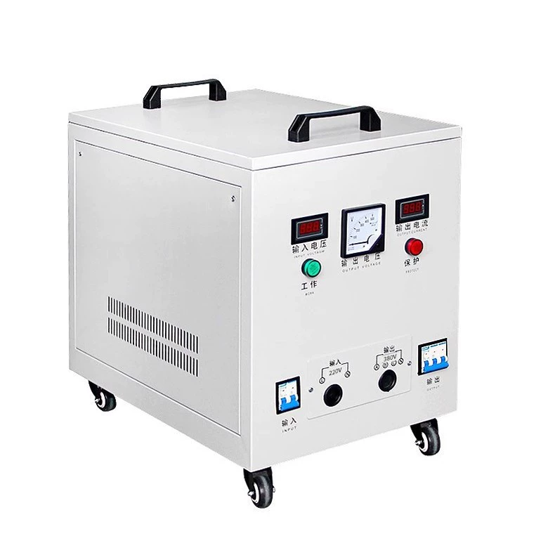
Choosing the right HVAC isolation transformer is one of those decisions that looks simple on paper but can be expensive in the field when done wrong.
A transformer with the correct voltage but the wrong VA rating can run hot for months, cause erratic controls, trip on startup, or fail during the worst possible weather window. In commercial and industrial HVAC work, that mistake can mean tenant complaints, service callbacks, frozen coils, lost production, or damaged electronics.
This guide is built to be practical. It covers the full HVAC isolation transformer sizing guide, explains how to select an HVAC control transformer, and provides real examples for single-phase isolation transformers for HVAC systems, HVAC transformer voltage and VA rating selection, and industrial HVAC electrical isolation transformer requirements.
Why the Right HVAC Isolation Transformer Matters
The right transformer does more than convert voltage. It protects the control side of the HVAC system from electrical noise, unwanted ground reference issues, and overload stress.
In practice, a properly selected isolation transformer helps keep relays pulling in cleanly, boards receiving stable voltage, and controls operating within their design range. That directly improves reliability and reduces nuisance service calls.
Downtime costs are not theoretical. In a retail building, a failed rooftop unit control transformer can shut down cooling for occupied zones in peak afternoon heat. In a plant, a noisy or overloaded control power source can disrupt PLC inputs and create process alarms that appear unrelated to HVAC at first glance.
Experienced technicians see the same pattern again and again: systems with transformers sized tightly to nominal load often have shorter service life than systems with healthy headroom.
Correct transformer selection helps prevent:
Overheating and insulation breakdown
Low secondary voltage under load
Relay chatter and contactor dropout
Premature control board failures
Nuisance fuse trips
Unexpected downtime during peak demand
Common HVAC Transformer Selection Problems
Most transformer problems are not caused by manufacturing defects. They start with bad assumptions during selection.
The first common issue is undersized VA capacity. A transformer may handle steady-state current on paper, but fail when several devices energize at once.
The second issue is voltage mismatch. A 240V primary in a system that actually sees 208V can produce lower-than-expected secondary voltage, especially under load. That matters on 24V controls, where a few lost volts can cause weak pull-in on relays and gas valves.
Another frequent problem is ignoring inrush current. Coils, contactors, motorized dampers, and certain electronic loads draw more current at startup than during normal operation.
Other recurring field problems include:
Assuming all 24V loads are “small”
Using control transformers where true isolation is needed
Overlooking ambient temperature inside crowded panels
Assuming grounding is automatically correct without design review
Adding accessories later without rechecking transformer load
One real-world example: a zoned residential air handler may begin life with a board and thermostat only, then later gain two dampers, a humidifier relay, and an air cleaner interface. What started as a comfortable 40 VA setup becomes a marginal installation very quickly.
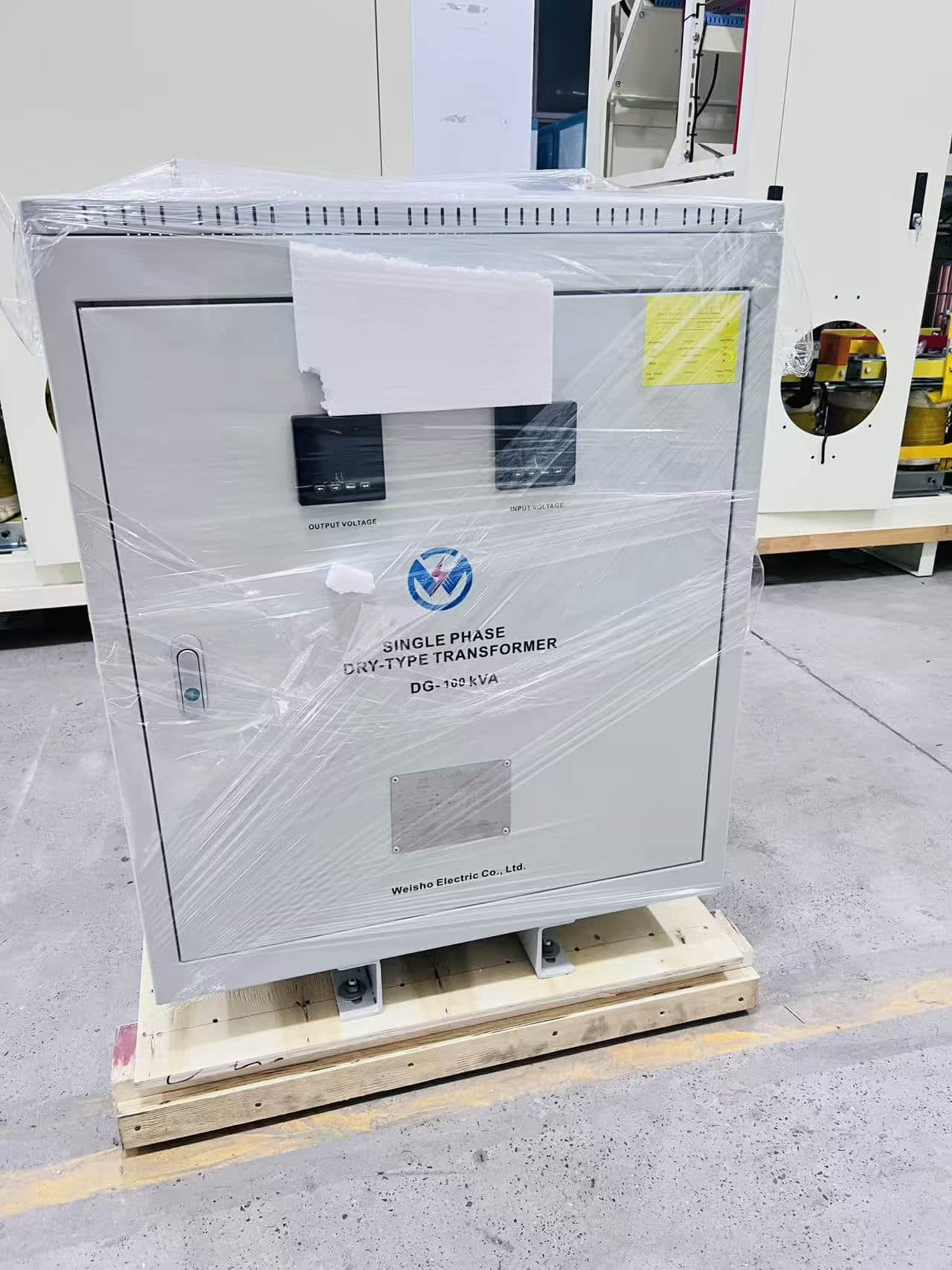
HVAC Isolation Transformer Basics for System Designers
Before sizing anything, it helps to define what the transformer is actually supposed to do in the system.
In HVAC, an isolation transformer is often used to separate sensitive controls from the incoming power system. That separation can reduce transferred noise, improve safety strategy, and create a cleaner control power source.
It may also be used to match voltage requirements while providing galvanic isolation between primary and secondary windings.
What Is an HVAC Isolation Transformer?
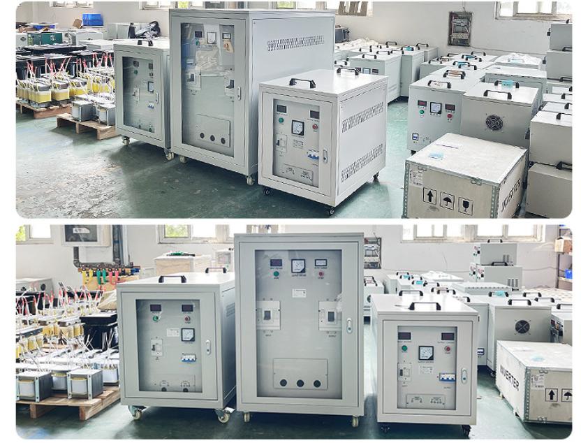
An HVAC isolation transformer is a transformer that provides electrical separation between the input supply and the output circuit so control or equipment power can be delivered more safely and with reduced transfer of electrical noise and fault effects.
Isolation Transformer vs Control Transformer in HVAC
These terms are related, but they are not identical.
A control transformer is primarily selected to provide the voltage needed by HVAC controls, such as stepping 240V down to 24V. An isolation transformer emphasizes electrical separation between primary and secondary circuits.
Some transformers do both. For example, a 480V-to-120V transformer feeding a rooftop control circuit may provide both voltage conversion and isolation.
The practical distinction is this:
Step-down transformer: changes voltage level
Control transformer: supplies power for control circuits
Isolation transformer: electrically separates circuits to improve protection and noise immunity
In many HVAC applications, the best device is a unit that combines control power functionality with isolation capability.
Single-Phase Isolation Transformer for HVAC Systems
A single phase isolation transformer for HVAC systems is commonly used in rooftop units, air handlers, boilers, condensing unit panels, BAS subpanels, and packaged equipment control cabinets.
Most low-voltage and small control power applications in HVAC are single-phase. That includes 24V thermostat circuits, 120V control branches, ignition controls, sensor power, and accessory circuits.
Single-phase units are especially common when a building has 480V distribution but control components require 120V or 24V isolated power.
How to Select an HVAC Control Transformer Step by Step
If you need a simple process, use this one every time. It is the most reliable way to avoid under-sizing and callback failures.
Step 1: Confirm Primary and Secondary Voltage
Start with the actual incoming supply voltage, not the voltage someone remembers from an old drawing.
Common primary voltages in HVAC include 120V, 208V, 240V, and 480V. Common secondary voltages include 24V and 120V.
Typical examples:
480V to 120V for rooftop unit control power
240V to 24V for furnace or air handler controls
120V to 24V for zone panels or add-on accessories
Be careful with 208V versus 240V systems. A transformer tapped or selected incorrectly may leave the secondary low enough to create intermittent control problems.
Step 2: Calculate Total Connected Load
List every device connected to the transformer secondary.
That includes much more than the thermostat. You need relays, contactor coils, control boards, gas valves, sensors, dampers, BAS controllers, actuators, alarm devices, and any planned accessories.
Common connected loads include:
Thermostats
Ignition modules
Gas valves
Relays and contactors
Control boards
Zone dampers
Humidifier relays
Condensate overflow switches
BAS sensors and actuators
Use manufacturer data whenever possible. If a device provides current draw in amps, note it. If it gives VA directly, even better.
Step 3: Convert Load to VA
The core formula is simple:
VA = Volts × Amps
If your secondary is 24V and the connected current is 1.5A, the running load is 36 VA.
If several devices are connected, add their individual VA values or add total current first and multiply by secondary voltage.
This is the basis of all HVAC transformer voltage and VA rating selection. If you skip it, you are guessing.
Step 4: Add Inrush and Safety Margin
Running VA is not the full story.
Relays, contactors, and actuators can draw significantly higher current for a brief period during energization. If the transformer is sized only for steady load, the secondary voltage may sag at startup.
A practical field rule is to add 20% to 30% extra capacity beyond calculated running load. In applications with high inrush, long wire runs, or expected add-ons, even more margin may be justified.
Why margin matters:
Helps maintain voltage during startup
Reduces heat stress on the transformer
Improves long-term reliability
Allows for minor future additions
Step 5: Check Frequency, Phase, and Environmental Conditions
Most North American HVAC systems use 60 Hz, but imported equipment or special applications may differ. Always verify frequency compatibility.
Also confirm whether the application is single-phase. Most control transformers in HVAC are, but not all systems are straightforward.
Then review the environment. A transformer mounted inside a cool, ventilated control cabinet has very different stress than one installed in a hot rooftop enclosure in direct sun.
Environmental checks should include:
Ambient temperature
Ventilation
Dust and lint exposure
Moisture or washdown risk
Vibration
Indoor or outdoor location
Required enclosure type
Step 6: Verify Code, Safety, and Manufacturer Requirements
The transformer must fit the application, but it must also fit the code environment and equipment instructions.
Review the HVAC equipment manufacturer’s documentation first. Many packaged units have specific requirements for acceptable control power source, overcurrent protection, grounding approach, and approved accessory loading.
On industrial projects, also verify panel standards, short-circuit considerations, and plant-specific electrical practices.
If you are selecting a product source, manufacturers with strong technical support can make this part much easier. For example, when engineers compare isolation and control power options for packaged equipment, suppliers such as Weisho Electric are often evaluated based on voltage combinations, build quality, enclosure suitability, and application support rather than price alone.
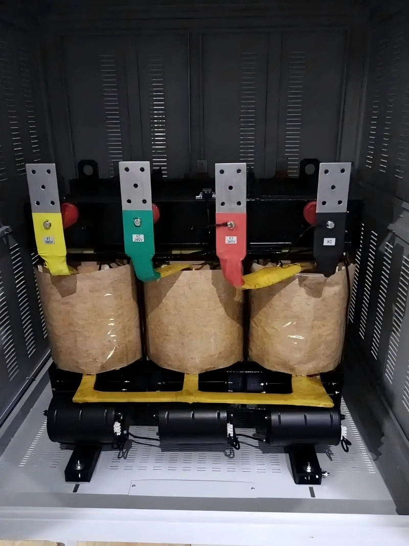
HVAC Isolation Transformer Sizing Guide
A practical HVAC isolation transformer sizing guide should not treat residential, commercial, and industrial systems as if they behave the same way. They do not.
Residential control transformers are often compact and cost-sensitive. Commercial systems add more accessories and wider voltage combinations. Industrial applications add harsher environments, more electrical noise, and stricter documentation expectations.
Formula for HVAC Transformer Voltage and VA Rating Selection
Use this formula as your basic sizing method:
Total VA = Secondary Voltage × Total Load Current
Then apply a margin rule:
Recommended Transformer VA = Calculated VA × 1.2 to 1.3 minimum
If the system includes high inrush devices, future accessory expansion, or long control wire runs, size above that minimum.
Example:
Secondary voltage = 24V
Total running current = 1.9A
Calculated VA = 24 × 1.9 = 45.6 VA
With 25% margin = 57 VA
Recommended standard size = 60 VA or 75 VA depending on inrush and future load
Recommended VA Sizing Buffer for HVAC Controls
In real HVAC work, a 20% to 30% buffer is often the difference between a transformer that survives and one that runs at its limit.
This extra capacity is not wasteful. It helps compensate for startup events, voltage fluctuation, internal heating, and load growth over time.
A tightly sized 40 VA transformer serving a 31 VA running load may look acceptable. But once a damper motor or extra relay is added, the design margin disappears.
When to Upsize an HVAC Isolation Transformer
There are times when upsizing is the smart choice, not overengineering.
Upsize when you have:
Long wire runs that increase voltage drop
Multiple relays or contactors energizing together
Motorized dampers or actuators with inrush demand
BAS expansion planned in a later phase
High ambient temperature inside the enclosure
Critical equipment where downtime is costly
For control reliability, modest oversizing is usually safer than operating near nameplate limits.
HVAC Transformer Voltage and VA Rating Selection Table
The table below gives quick, practical reference points for HVAC transformer voltage and VA rating selection.
| HVAC Application | Typical Primary Voltage | Typical Secondary Voltage | Common Load Type | Estimated VA Range | Selection Tip |
|---|---|---|---|---|---|
| Thermostat/control circuit | 120V | 24V | Low-voltage controls | 20-40 VA | Suitable for basic residential controls |
| Furnace/air handler controls | 240V | 24V | Relays, gas valve, board | 40-75 VA | Add margin for accessories |
| Rooftop unit controls | 480V | 120V/24V | Contactors, boards, sensors | 75-250 VA | Verify inrush and accessory count |
| Building automation panel | 120V/240V | 24V | BAS devices and sensors | 50-150 VA | Size for future points expansion |
| Industrial HVAC panel | 480V | 120V | Mixed controls and isolation needs | 150-1000+ VA | Confirm industrial protection and code requirements |
Real-World HVAC Isolation Transformer Sizing Examples
Examples are where theory becomes useful. The numbers below reflect the kind of calculations technicians and designers make in actual HVAC work.
Example 1: Residential Air Handler 24V Control Transformer
Consider a residential air handler with the following 24V connected loads:
Thermostat and control logic: 0.10A
Control board: 0.35A
Fan relay coil: 0.25A
Gas valve or accessory relay equivalent: 0.30A
One motorized damper: 0.30A running, higher at actuation
Total running current = 1.30A
Calculated VA = 24V × 1.30A = 31.2 VA
On paper, some installers would choose a 40 VA transformer and move on. But that is where field experience matters.
If the damper has a higher actuation draw, or a humidifier relay is added later, the 40 VA unit can become marginal. Add a 25% buffer, and you get 39 VA before even accounting for future accessories. That means a 50 VA transformer is often the better long-term choice.
This is why many callback-prone systems are not actually “mysteriously bad.” They were just sized too close.
Example 2: Commercial Rooftop Unit Isolation Transformer
Now take a light commercial rooftop unit with 480V incoming power and a 120V isolated secondary for controls.
Connected 120V loads:
Main control board: 0.20A
Two contactor coils: 0.18A each = 0.36A
Smoke detector/control interface: 0.10A
Sensor package and auxiliary relays: 0.14A
Total running current = 0.80A
Calculated VA = 120V × 0.80A = 96 VA
With a 25% margin, the minimum target becomes 120 VA. Since standard sizes do not always align exactly, a 150 VA 480V-to-120V isolation transformer is usually the practical recommendation.
That selection also gives breathing room if a BAS interface, condensate alarm, or occupancy interlock is added later.
Example 3: Industrial HVAC Electrical Isolation Transformer Requirements
Industrial applications often look acceptable by VA alone, but fail once the full environment is considered.
Imagine a process cooling air-handling control panel in a manufacturing plant with 480V supply and 120V isolated control power. The loads include PLC I/O relays, alarm horn logic, pressure switches, control relays, and monitoring interfaces.
Connected current totals 4.2A on the 120V side.
Calculated VA = 120V × 4.2A = 504 VA
With a 25% margin, the target is 630 VA. In practice, a 750 VA transformer is a common next step.
But the final selection must also consider:
Dust and airborne oil in the plant
High panel ambient temperature near process equipment
Electrical noise from nearby VFDs
Grounding method used by plant standards
Short-circuit current available at the panel
Panel listing and internal component spacing
This is where industrial HVAC electrical isolation transformer requirements differ sharply from ordinary commercial practice. The transformer is part of the control power architecture, not just a voltage accessory.
Real-World Data Table: Sample Load and VA Calculation Examples
The table below summarizes realistic sample calculations that designers can use as a starting reference.
| Scenario | Connected Devices | Running Load (A) | Secondary Voltage | Calculated VA | Recommended Transformer Size |
|---|---|---|---|---|---|
| Residential air handler | Board, relay, gas valve, thermostat | 1.3A | 24V | 31.2 VA | 40-50 VA |
| Zoned residential system | Board, 2 dampers, thermostat, relay | 1.9A | 24V | 45.6 VA | 60-75 VA |
| Small RTU controls | Contactors, board, sensors | 0.8A | 120V | 96 VA | 150 VA |
| BAS control panel | Sensors, actuators, controller | 2.5A | 24V | 60 VA | 75-100 VA |
| Industrial HVAC control panel | Multiple relays, PLC I/O, alarms | 4.2A | 120V | 504 VA | 750 VA |
These values are not code substitutes, but they do reflect common field conditions. They also show why a nameplate-only approach is risky.
Industrial HVAC Electrical Isolation Transformer Requirements
Industrial sites place higher demands on transformers than most comfort-cooling installations.
The electrical environment is harsher. The reliability expectations are higher. The cost of failure is usually much greater.
Environmental Ratings and Enclosure Selection
Industrial HVAC transformers may be exposed to dust, corrosive particles, vibration, washdown, or sustained elevated ambient temperatures.
A transformer that performs well in a clean office mechanical room may fail early in a production area if enclosure and thermal conditions are ignored.
Review these factors carefully:
Dust loading from manufacturing processes
Moisture and condensation risk
Oil mist or chemical exposure
Outdoor weather exposure
Vibration from adjacent machinery
Internal panel temperature rise
In many industrial projects, product selection also includes physical construction quality and insulation system durability. That is one reason specifiers may compare manufacturers such as Weisho Electric for product fit when selecting an isolation transformer for HVAC control panels or mixed-use industrial equipment.
Harmonics, Noise, and Sensitive Controls
Industrial HVAC controls often live near VFDs, switching power supplies, welders, and large motor systems. These create electrical noise that can interfere with sensitive electronics.
Isolation helps reduce the transfer of common-mode noise and can improve control stability for PLC inputs, analog sensors, communication modules, and BAS devices.
This matters especially when HVAC is tied into process ventilation, clean rooms, pharmaceutical spaces, or data-critical environmental control zones.
Isolation may be especially valuable when serving:
PLC-based control panels
VFD-adjacent control circuits
Analog transducers and sensors
Networked building automation devices
Alarm and monitoring systems
Grounding, Shielding, and Safety Compliance
Grounding should never be left to assumption.
The secondary grounding method must align with equipment design, plant standards, and applicable electrical rules. In some cases, shielded transformer designs or careful secondary bonding strategies are used to improve noise performance and fault response.
Safety compliance is also broader in industrial settings. Beyond ordinary voltage and VA, teams may need to review panel integration, overcurrent protection, conductor sizing, touch safety, and inspection documentation.
When problems arise in the field, grounding misunderstandings are often part of the story. A transformer can be electrically correct in voltage and still create unreliable controls if the grounding scheme is inappropriate for the system architecture.
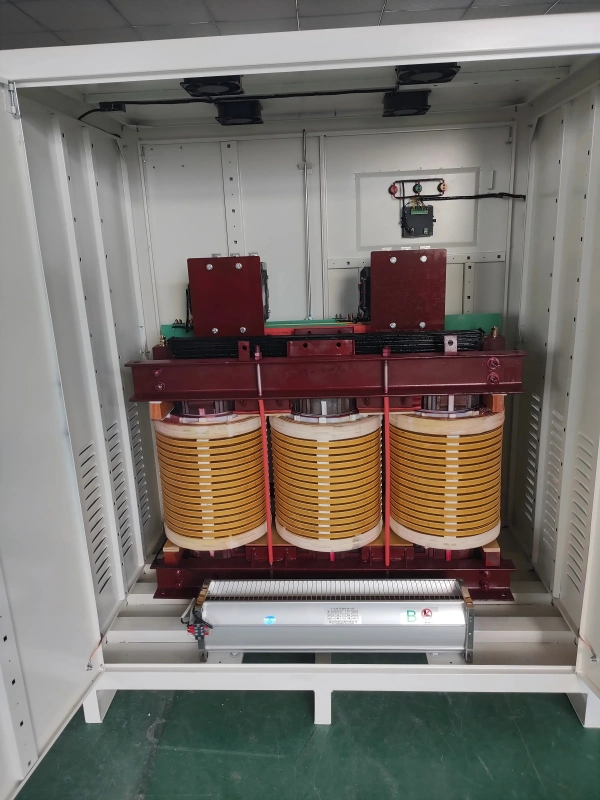
Mistakes to Avoid When Choosing an HVAC Isolation Transformer
Good transformer selection is often about avoiding a handful of predictable errors.
Selecting by Voltage Only
This is the classic mistake.
Matching 480V to 120V or 240V to 24V does not mean the transformer is adequate. If the VA rating is too low, the unit will run overloaded and may fail long before anyone suspects the true cause.
Ignoring Inrush Current
Relays and contactors rarely care what your spreadsheet says about running load. They care whether enough current is available when they pull in.
If inrush is ignored, secondary voltage can dip at exactly the wrong time. That leads to chattering, nuisance trips, or unstable startup.
Forgetting Expansion Capacity
HVAC systems grow. Accessories get added.
Today’s simple control circuit often becomes tomorrow’s zone panel, IAQ package, BAS tie-in, or alarm interface. A transformer sized with no reserve usually becomes a service problem later.
Overlooking Installation Conditions
Heat kills transformers quietly.
A correctly sized transformer installed in a cramped, poorly ventilated, high-temperature enclosure may still fail early. Rooftop solar gain, dirty filters in enclosure vents, and proximity to hot equipment all matter more than many spec sheets suggest.
Quick HVAC Isolation Transformer Selection Checklist
Use this checklist before approving any final selection.
| Checkpoint | What to Verify | Why It Matters |
|---|---|---|
| Primary voltage | Actual incoming supply voltage | Prevents mismatch and equipment damage |
| Secondary voltage | Required control/equipment voltage | Ensures correct operation |
| VA load | Total running and inrush demand | Prevents overheating |
| Safety margin | 20%-30% extra capacity | Improves reliability |
| Phase/frequency | Single-phase and 50/60 Hz match | Avoids compatibility issues |
| Environment | Heat, dust, moisture, enclosure type | Supports service life |
| Compliance | Code and manufacturer instructions | Reduces safety and inspection risk |
FAQ
How do I size an HVAC isolation transformer?
Start by adding the total connected load on the secondary side in amps. Multiply that current by the secondary voltage to get VA, then add capacity for inrush current and a safety margin of about 20% to 30%. That simple process is the foundation of any reliable HVAC isolation transformer sizing guide.
What VA rating do I need for a 24V HVAC control transformer?
The required VA depends on the combined load of every connected device, including the board, relays, thermostat, dampers, and accessories. In many HVAC systems, common selections range from 40 VA to 75 VA, but the right answer always comes from actual load calculation rather than a generic rule.
Can I use a larger transformer than required in an HVAC system?
Yes, moderate oversizing is usually acceptable and often beneficial, as long as the voltage matches the application and the installation follows manufacturer requirements. A slightly larger transformer generally runs cooler and provides better tolerance for inrush and future accessory additions.
What is the difference between an isolation transformer and a control transformer in HVAC?
An isolation transformer focuses on electrical separation between primary and secondary circuits, while a control transformer is mainly used to provide the voltage needed for control circuits. In HVAC practice, some transformers perform both functions at the same time by stepping voltage down and isolating the control side from the supply.
When is a single-phase isolation transformer used in HVAC systems?
It is commonly used in rooftop units, air handlers, boilers, control panels, and other applications where single-phase control power is needed. These units are especially common when HVAC controls require isolated 24V or 120V power derived from a higher-voltage building supply.
What causes HVAC control transformers to fail?
Common causes include overload, short circuits, voltage mismatch, inrush stress, overheating, poor ventilation, and unsuitable installation conditions. In the field, many failures trace back to underestimating actual connected load or adding accessories later without rechecking transformer capacity.
Are industrial HVAC transformer requirements different from commercial systems?
Yes. Industrial systems often require stricter review of enclosure rating, thermal conditions, electrical noise isolation, grounding method, compliance documentation, and mechanical durability. In many facilities, the transformer must perform reliably in harsher environments and around more sensitive controls than in ordinary commercial buildings.
Get Expert Help Choosing the Right HVAC Isolation Transformer
If you are selecting a transformer for an HVAC system, do not rely on voltage alone and do not size to the absolute minimum.
Review the actual primary voltage, required secondary voltage, total connected load, inrush demand, installation environment, and applicable equipment instructions before making the final choice.
That extra review time is far cheaper than field failures, emergency replacements, and repeated diagnostics on unstable controls.
Need a dependable answer for your project? Gather your load list, wiring details, ambient conditions, and expansion plans, then speak with a qualified supplier or electrical engineer today. Choose the safest, most reliable HVAC isolation transformer now so your system starts cleanly, runs cooler, and stays online when it matters most.