What is the difference between a control transformer and an isolation transformer?
A control transformer is designed to keep the secondary voltage stable when relays, solenoids, and contactors experience hard momentary inrush in industrial control circuits. In contrast, an isolation transformer is designed primarily for galvanic isolation, safety separation, grounding control, and noise reduction. If your main problem is reliable pull-in of coils in a machine panel, choose a control transformer. If your main problem is electrical safety, ground loop separation, common-mode noise, or protecting sensitive electronics, choose an isolation transformer.
I have seen this mistake repeatedly in retrofit lines, packaging machines, and CNC control cabinets: someone installs “a transformer that matches the voltage,” the panel powers up, and then the contactor chatters, the PLC reboots, or inspection flags the grounding approach. In real projects, the label is not enough. The design intent matters.
The Short Answer Buyers, Engineers, and Panel Builders Need
The shortest practical rule is this: use a control transformer for actuation loads and use an isolation transformer for separation loads. That sounds simple, but it solves most of the confusion behind the search for a control transformer vs. an isolation transformer.
In the field, the arguments usually come down to three questions. Will contactors pull in cleanly? Will the electronics stay stable? Will the installation pass safety and grounding review under the applicable standard and local code interpretation?
From my own panel troubleshooting work, the fastest way to decide is to list what the secondary is feeding. If it mostly feeds coils, use a control transformer. If it mostly feeds electronics, instrumentation, communication equipment, test devices, or anything noise-sensitive, an isolation transformer is often the better fit.
Why This Confusion Costs Money in Real Projects
Wrong transformer selection looks cheap on a quote sheet and expensive on the plant floor. I have personally measured secondary sag in older machine panels where generic step-down units dropped enough voltage during contactor pull-in to cause nuisance relay dropout.
That leads to very specific costs:
Contactor chatter during line dips or simultaneous coil energization
Overheating from poor sizing assumptions
PLC and HMI reset when noisy coils share the same supply
Failed inspections due to undocumented secondary bonding choices
Ground loop noise on analog signals and communications
Over-specification of expensive transformers, where a simpler design would work
One maintenance manager told me his team replaced three contactors before realizing the real issue was not the contactor at all. The 120 V control circuit was fed by a general-purpose transformer with poor regulation under inrush. Once a properly sized control transformer was installed, the chatter disappeared.
That kind of story is common among practicing electricians and panel builders. The repeated theme is simple: a control transformer is not just any step-down transformer, and isolation alone does not guarantee stable control power.

Control Transformer vs Isolation Transformer: Featured Snippet Definition Table
| Factor | Control Transformer | Isolation Transformer |
|---|---|---|
| Primary purpose | Stable control voltage under coil inrush | Galvanic isolation, safety separation, noise reduction |
| Typical use | Industrial control circuits | Sensitive electronics, separate power domains, safer maintenance schemes |
| Voltage behavior | Designed to limit excessive secondary drop during inrush | Varies by design; not always optimized for intermittent high inrush loads |
| Inrush handling | Strong emphasis | Usually secondary concern unless specifically designed for it |
| Winding design priority | Regulation during relay/contactor energization | Isolation integrity and circuit separation |
| Safety role | Provides isolation, but not its main application focus | Main application focus is electrical separation and grounding strategy |
| Typical loads | Contactors, relays, solenoids, motor starters | PLCs, HMIs, instrumentation, test equipment, communications |
| Machine panel use | Best for coil-heavy control sections | Best for clean/sensitive sections or separated subsystems |
| Cost pattern | Often cost-effective for control circuits | Can cost more depending on shielding, ratings, and enclosure |
What Is a Control Transformer?

A control transformer is a specialized step-down transformer used in industrial control circuits. Its key job is to provide a dependable secondary voltage when electromagnetic loads draw a short, heavy inrush current.
That is why the phrase control transformer applications in industrial control circuits matters more than many buyers realize. These transformers are selected not just by output voltage, but by how well they support pull-in current for coils and then settle into the lower sealed load.
In practice, a relay coil may need a brief surge to close, and a contactor coil may demand a much higher momentary VA than its nameplate sealed VA suggests. A good control transformer is engineered around that reality.
Typical control transformer applications in industrial control circuits
Machine control panels
Motor starter circuits
Contactor and relay control power
Solenoid valve circuits
CNC and automation cabinets
Conveyor control stations
Packaging and material handling systems
On one bottling line retrofit I worked around, nearly every nuisance stop traced back to coil behavior. The panel had enough voltage on paper, but not enough real-world stability when two solenoids and a contactor pulled in together. That is exactly where a properly sized control transformer earns its keep.
What Is an Isolation Transformer?

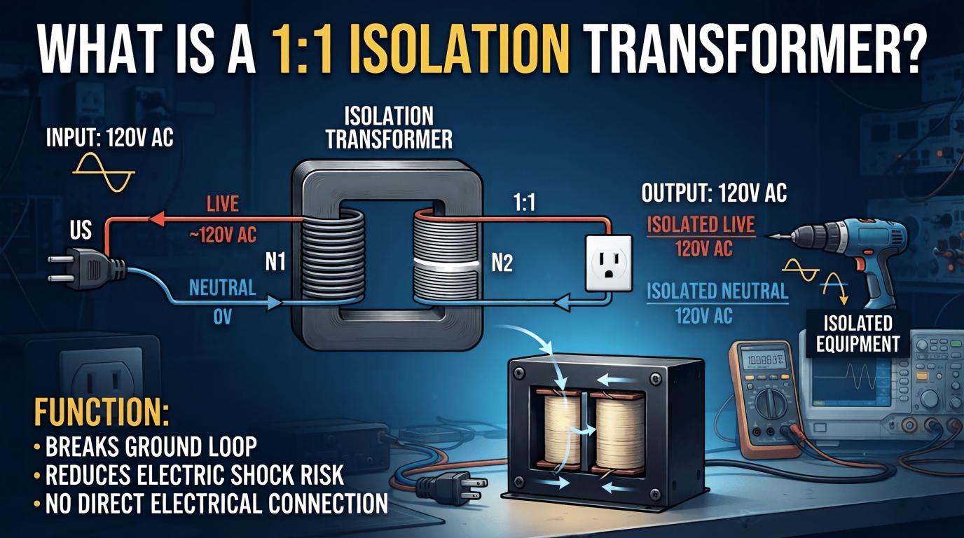
An isolation transformer is a transformer with primary-to-secondary galvanic isolation. It separates one circuit from another so there is no direct conductive path, which supports safety, grounding flexibility, and noise control.
In search language, this is the heart of isolation transformer electrical safety and galvanic isolation. The transformer is used to separate source and load electrically, often to reduce common-mode noise, limit propagation of certain disturbances, and create a cleaner power environment for sensitive devices.
Isolation transformers may be 1:1 or step-up/step-down. The important point is not just the turn ratio. It is the quality of isolation and how that isolation fits the grounding method, shielding strategy, and equipment sensitivity.
Isolation transformer electrical safety and galvanic isolation
Galvanic isolation reduces direct conductive coupling between input and output. That can help limit the transfer of some faults and reduce the impact of shared noise on vulnerable circuits.
It can also help with common-mode interference, especially when paired with proper shielding, correct cable routing, and a disciplined bonding scheme. But an isolation transformer is not magic. If the panel has poor grounding, sloppy shield terminations, or noisy output wiring bundled with analog inputs, the transformer alone will not save the installation.
Relevant design and installation decisions are often evaluated against frameworks and equipment requirements associated with IEEE guidance and IEC standards, including transformer safety, insulation, panel construction, and control equipment practices. In real procurement reviews, buyers and engineers should confirm which exact product standard, insulation class, and panel integration requirement applies, not just rely on the word “isolated.”
The Core Difference Between a Control Transformer and an Isolation Transformer
The real difference is design priority. A control transformer prioritizes voltage regulation during intermittent inrush. An isolation transformer prioritizes isolation integrity and electrical separation.
Both may isolate primary from secondary. Both may step the voltage up or down. Both may appear interchangeable to someone reading only volts and VA. But in real use, the wrong choice shows up fast.
That is the clearest answer to the question about the difference between a step-down control transformer and an isolation transformer. Even if both reduce voltage, only the control transformer is specifically optimized for the control circuit inrush performance.
Side-by-Side Comparison: Control Transformer vs Isolation Transformer for Machine Panels
| Machine Panel Scenario | Better Choice | Why |
|---|---|---|
| Multiple contactors and relays are energized frequently | Control transformer | Better secondary voltage stability during inrush |
| PLC/HMI resets caused by noise | Isolation transformer | Better separation and a cleaner power strategy |
| Mixed analog sensors and noisy solenoids in one cabinet | Often both | Split dirty coil loads from sensitive electronics |
| Field device isolation for troubleshooting | Isolation transformer | Supports a separate power domain and maintenance strategy |
| Basic 480 V to 120 V control power for motor starter panel | Control transformer | Classic control transformer application |
| Communication equipment with ground loop issues | Isolation transformer | Helps separate reference and reduce noise paths |
| Legacy retrofit panel with coil chatter | Control transformer | More likely to solve pull-in sag than generic isolation |
| High-sensitivity test bench | Isolation transformer | Safety separation and cleaner supply priority |
How a Control Transformer Handles Inrush Better Than a General Isolation Transformer
Coils do not behave like steady resistive loads. Their first instant of energization can demand several times the steady-state VA.
A control transformer is designed so that when that surge happens, the secondary does not collapse so badly that the relay fails to pull in. That is critical in production because a contactor that only half-closes or chatters is not a minor nuisance. It creates heat, arcing, wear, and downtime.
Three practical sizing truths matter:
Inrush VA matters more than sealed VA at startup
Simultaneous coil operation matters more than single-load assumptions
Voltage drop during pull-in matters more than nameplate voltage alone
I have tested panels where everything looked fine at idle, but the moment two coils pulled together, the secondary dipped enough to flicker pilot lights and momentarily upset the logic supply. A generic isolation transformer of the same nominal voltage and broad VA rating did not perform like a proper control transformer under that duty.
When to Choose a Control Transformer
Choose a control transformer when your main task is to provide stable control power, often stepping line voltage down to 120 V, 24 V, or another standard control level for industrial actuation loads.
This is especially true in motor control centers, machine panels, and OEM equipment, where relays and contactors switch all day. If the load profile is intermittent, inductive, and inrush-heavy, a control transformer is usually the right answer.
Choose it for relay, solenoid, and contactor loads
Repeated coil energization creates short bursts of demand that ordinary voltage-based selection can miss. A control transformer is meant for this exact environment.
This makes it the default answer for classic control transformer applications in industrial control circuits. When actuation reliability drives uptime, control transformers usually outperform general-purpose alternatives.
Choose it when stable control voltage matters more than broad power isolation
Many machine builders do not need advanced clean-power separation on every secondary. They simply need coils to pull in every time, even when plant voltage sags slightly or several loads switch together.
For those panels, the best answer to control transformer vs isolation transformer for machine panels is often straightforward: use a control transformer for the dirty, inductive control section.
When to Choose an Isolation Transformer
Choose an isolation transformer when the main need is separation between source and load. That includes personnel protection strategy, noise control, reference separation, and cleaner supply conditions for sensitive equipment.
In many modern automation cabinets, the electronics are now more failure-sensitive than the coils. As PLCs, drives, HMIs, network switches, and analog modules become more integrated, isolation becomes more valuable.
Choose it for sensitive electronics and noise reduction
Use an isolation transformer for PLCs, instrumentation, communications, test benches, and other subsystems where small disturbances cause big consequences. If the panel has analog signals drifting when a solenoid bank fires, isolation should be part of the design discussion.
Medical-adjacent, laboratory, and validation setups also often prioritize clean separation. The point is not only safety. It is signal integrity and predictable behavior.
Choose it for grounding separation and maintenance safety strategy
An isolation transformer can support a deliberate grounding and bonding plan where allowed by code and equipment requirements. It is useful when troubleshooting ground-loop issues or separating field wiring noise from control electronics.
But this is where many teams get in trouble. Floating versus bonded secondary choices must be documented, intentional, and compliant with the applicable rules. More than once, I have seen otherwise good panels fail review because the transformer was acceptable, but the secondary grounding method was undocumented or inconsistent.
Difference Between Step-Down Control Transformer and Isolation Transformer
| Question | Step-Down Control Transformer | Isolation Transformer |
|---|---|---|
| Can it reduce voltage? | Yes | Yes, depending on the design |
| Does it provide primary-secondary isolation? | Yes | Yes |
| Optimized for contactor/relay inrush? | Yes | Not necessarily |
| Best for control coils? | Yes | Usually no, unless specifically rated for that duty |
| Best for clean power separation? | Sometimes, but not the main reason to use it | Yes |
| Main selection driver | Control load behavior | Safety, noise, separation |
Real-World Sizing Example: Machine Panel With Contactors, PLC, and HMI
Consider a machine panel with a 480 V primary. The builder needs 120 V for contactors and solenoids, plus clean, low-noise power for a PLC, HMI, and analog I/O power supply.
| Load | Voltage | Load Type | Key Sizing Concern | Best Supply Strategy |
|---|---|---|---|---|
| 2 contactor coils | 120 V | Inductive | High inrush during pull-in | Control transformer |
| 4 solenoid valves | 120 V | Inductive | Frequent cycling and combined inrush | Control transformer |
| PLC power supply | 120 V input | Electronic | Noise immunity, stable supply | Isolation transformer or separate clean branch |
| HMI | 120 V input | Electronic | Sensitive to dips and interference | Isolation transformer or separate clean branch |
| Analog transmitter power supply | 120 V input | Sensitive electronic | Common-mode noise, grounding quality | Isolation transformer preferred |
In the best-performing panels I have seen, builders often split the loads. One control transformer feeds the coil side. One isolated clean-power branch feeds the electronics.
That approach costs more up front. It also prevents a lot of ugly troubleshooting later.
What Reddit, Quora, and Field Discussions Commonly Get Right
Across real practitioner discussions and service calls, four themes come up again and again.
A control transformer is not just any step-down transformer
Isolation alone does not guarantee clean control power
Grounding mistakes cause more failures than transformer label choice
Panel builders often split dirty and clean loads
That last point is especially valuable. Experienced panel shops rarely force one transformer to solve every problem. They know that a shared secondary feeding both coil surges and sensitive logic is often asking for intermittent faults.
One controls technician summarized it well during a commissioning job: the coil side is where the electrical punches happen, and the PLC side is where the complaints happen. That is not textbook language, but it is accurate.
What Practitioners Still Get Wrong
Even experienced teams make these mistakes:
Using a generic isolation transformer for high-inrush control loads
Oversizing blindly by nameplate VA without checking pull-in VA
Ignoring secondary fusing and branch protection
Assuming a floating secondary is automatically safer or cleaner
Mixing analog and coil returns carelessly
Choosing by price before reviewing the duty cycle and fault history
The biggest sizing error I see is treating sealed VA as the whole story. In reality, the contactor pull-in is the moment that determines whether the machine starts reliably.
The biggest wiring error is poor grounding logic. I have watched teams swap PLCs, power supplies, and cables when the real issue was a noisy shared reference and a badly planned secondary bond.
Common On-Site Pain Points
There are small details that matter in actual cabinets.
Contactor chatter during brownout is one of them. In summer afternoons on heavily loaded industrial feeders, a panel that worked perfectly in the shop may start chattering on site because real utility voltage is lower and multiple loads switch together.
Intermittent PLC resets when coils share the same secondary is another. It may only happen once every few shifts, which makes everyone suspect software first. But if you trend the supply during valve actuation, the cause becomes obvious.
Transformer hum complaints also show up in retrofit panels, especially in thin-door enclosures or older installations where mounting surfaces amplify vibration. The wrong transformer is not only an electrical problem. It becomes a maintenance annoyance people notice every day.
Inspection issues caused by undocumented bonding choices are very real. If the panel drawing, labeling, and as-built grounding method do not match, the transformer decision becomes part of a larger compliance problem.
These are not theoretical issues. They are the reasons seasoned plant electricians often ask first, “What is this transformer feeding?” before they ask anything else.

Selection Framework: How to Choose in 5 Practical Steps
1. Define the load type. Separate coil loads from electronic loads immediately.
2. Calculate inrush VA and sealed VA. Do not rely on steady-state current alone.
3. Identify the safety or isolation requirement. Decide whether galvanic separation is central to the application.
4. Review grounding and noise environment. Check analog signals, communication wiring, shielding, and known plant noise issues.
5. Confirm code, standards, and panel constraints. Verify enclosure space, temperature rise, protection, and applicable IEEE, IEC, and equipment requirements.
If, after step one, your answer is “mostly contactors and relays,” start with a control transformer. If the answer is “mostly electronics and noise-sensitive devices,” start with an isolation transformer. If it is both, the best design may be two separate supplies.
Specification Checklist Before You Buy
| Specification Item | Why It Matters |
|---|---|
| Primary voltage | Must match actual supply, not just nominal system assumption |
| Secondary voltage | Must match the control circuit or electronic input requirement |
| VA rating | Base capacity for expected load |
| Inrush VA capability | Critical for relays, solenoids, and contactors |
| Temperature rise | Affects reliability and enclosure heat management |
| Impedance/regulation behavior | Important for voltage stability under transient loading |
| Electrostatic shielding | Useful for noise-sensitive isolation applications |
| Enclosure/open type | Must fit panel construction and environment |
| Standards compliance | Supports safety, procurement approval, and inspection readiness |
| Mounting requirements | Impacts vibration, hum, space, and serviceability |
For standards, check the exact manufacturer declarations and system requirements. Depending on product category and installation, teams commonly review transformer construction and control panel integration against relevant IEC and IEEE expectations, along with local regulatory rules and customer specifications.
Cost, Reliability, and Maintenance Trade-Offs
The wrong transformer often looks cheaper only before the first downtime event. After one production stop, one emergency callout, or one recurring nuisance fault, the savings disappear.
A control transformer can be the most economical choice for a coil-heavy panel because it targets the real duty. An isolation transformer can save money where electronic stability, troubleshooting speed, and signal quality matter more than raw coil performance.
From a maintenance perspective, separating dirty and clean supplies is easier to diagnose. When coils and electronics are split, failures become more visible, and technicians spend less time guessing whether a reset came from software, field wiring, or control power collapse.
Best Outline for Procurement, OEM, and Maintenance Teams
OEM panel designer
Design around load behavior, not just voltage. Use a control transformer for coil banks and a separate isolated source for sensitive electronics when reliability matters.
Plant electrician
When troubleshooting chatter or nuisance resets, verify secondary voltage during inrush before replacing components. The transformer may be the hidden cause.
Maintenance manager
Track repeat faults by circuit type. If coil events and logic resets correlate, splitting transformer duties can reduce downtime dramatically.
Procurement buyer
Do not compare transformers on voltage and VA alone. Ask for inrush performance, regulation data, shielding options, standards compliance, and intended application category.
FAQ
What is the main difference between a control transformer and an isolation transformer?
A control transformer is optimized to hold voltage during coil inrush in industrial control circuits, while an isolation transformer is optimized for galvanic isolation, safety separation, and noise reduction.
Can a control transformer also provide isolation?
Yes, it provides primary-to-secondary isolation, but its design purpose is stable control voltage under inrush rather than the broader system role typically expected from an isolation transformer.
Can I use an isolation transformer instead of a control transformer?
You can in some cases, but it is often a poor choice for high-inrush industrial control loads unless the unit is specifically suitable for that duty and sized for the actual pull-in demands.
Which is better for a machine control panel?
For coil-heavy control circuits, a control transformer is usually better; for sensitive PLC, HMI, analog, or communication subsystems, an isolation transformer is often better.
Is a control transformer just a step-down transformer?
No, it is a specialized step-down transformer designed to maintain usable secondary voltage during relay, solenoid, and contactor inrush.
Do I need separate transformers for PLCs and contactors?
Often yes, especially in noisy or critical panels, because separating dirty inductive loads from sensitive electronics improves stability and simplifies troubleshooting.
Does an isolation transformer improve electrical safety?
Yes, it can improve safety through galvanic isolation and circuit separation, but the real safety result still depends on correct grounding, bonding, overcurrent protection, and code-compliant installation.
How do I size a control transformer correctly?
Size it using inrush VA, sealed VA, simultaneous load behavior, acceptable voltage drop during pull-in, and a practical margin for future additions.
How do I size an isolation transformer correctly?
Size it by continuous load, startup behavior of the connected electronics, shielding and noise-control needs, thermal limits, and the intended grounding method of the secondary.
The Practical Recommendation
The practical recommendation is simple. Control transformers are for dependable actuation in industrial control circuits. Isolation transformers are for separation, safety, and cleaner power.
If your load is relays, contactors, and solenoids, choose the transformer built to survive inrush. If your load is PLCs, HMIs, instrumentation, communication gear, or a troubleshooting-sensitive subsystem, choose the transformer built for galvanic isolation and power separation.
And if your panel contains both, do what the best field-proven designs often do: split the loads. That choice solves more real problems than trying to force one transformer to do two different jobs badly.
Get the Right Transformer Before Your Next Downtime Event
Before you buy, review your panel load list, grounding scheme, and known noise symptoms. If you want a fast and accurate recommendation, get a transformer selection review, inrush sizing check, or machine-panel application assessment now.
Do not wait for the next nuisance trip, PLC reset, or inspection delay. Choose the transformer that matches the load, and prevent the downtime event before it happens.