Can an isolation transformer prevent electric shock?
Yes—but only in the right scenario. An isolation transformer can reduce electric shock risk by breaking the direct conductive path to ground, but it does not make a circuit shock-proof. If your real problem is earth-referenced shock, leakage current, fault transfer from the mains, or noisy shared grounds, an isolation transformer is often the right tool. If the risk is touching both secondary conductors, working in wet contact conditions, or relying on one device to replace a full protection scheme, it is not enough.
That distinction is where buyers, technicians, and even facility managers get into trouble. In real field work, I have seen portable service benches made much safer with isolation transformers, and I have also seen dangerous installations where people assumed “isolated” meant “harmless.” It does not.
The practical selection rule is simple: choose an isolation transformer based on application, load type, grounding method, leakage behavior, and fault strategy. A medical room, an industrial panel, a repair bench, and a marine AC system should never be specified the same way.
Why the Short Answer Is Yes—But Only in the Right Wiring Scenario
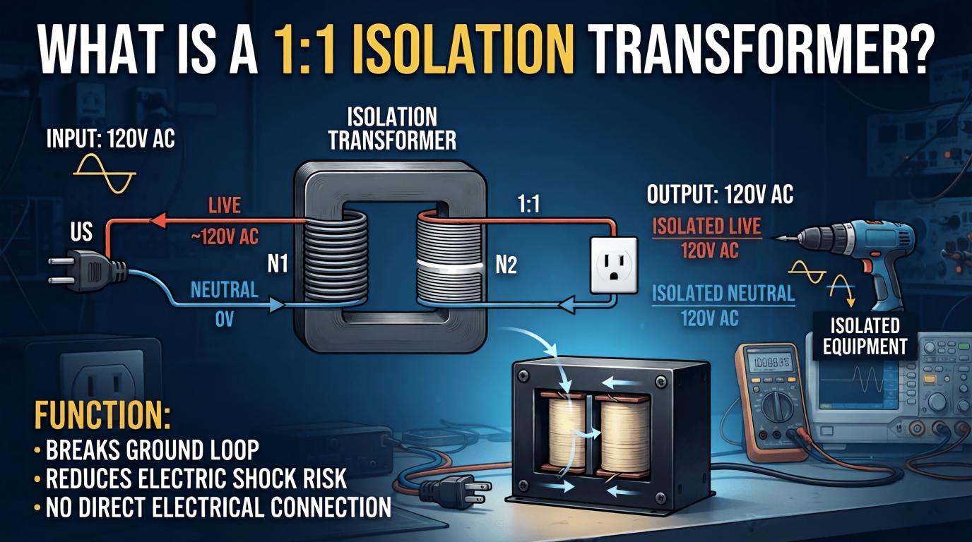
An isolation transformer helps because the primary and secondary are separated. There is no direct metallic connection from incoming mains to the isolated output.
That means a person touching one isolated conductor and earth often does not complete the same fault path that exists on a grounded utility supply. This is the core of electric shock protection with isolation transformers.
But there is a hard limit. If someone touches both secondary conductors, current can still flow through the body. If the secondary is bonded incorrectly, the original shock path can also come back.
So the answer to “can an isolation transformer really prevent electric shock?” is: it can prevent some of the most common shock paths, especially line-to-ground or earth-referenced faults, but it cannot eliminate all shock hazards.

What Problem Isolation Transformers Actually Solve
Most buyers ask the wrong first question. They ask about “shock prevention,” when the real engineering question is: what failure mode are you trying to control?
In practice, isolation transformers are used to address several distinct hazards and pain points:
Leakage current from line to earth through filters, cable capacitance, or parasitic paths
Ground loops cause hum, unstable measurements, or communication errors
Touch voltage on chassis or machine frames
Nuisance tripping where cumulative leakage causes protective devices to trip
Fault propagation from dirty mains into sensitive or critical loads
Reference isolation for maintenance and live troubleshooting
These are not theoretical issues. In factories, imported equipment with aggressive EMI filtering often leaks enough current to create mystery trips. In hospitals, patient-area systems cannot tolerate a casual leakage design. In service work, grounded oscilloscopes can instantly create a destructive short if connected to non-isolated live chassis equipment.
Why People Still Ask: “Can an Isolation Transformer Really Prevent Electric Shock?”
The debate keeps returning because many people confuse isolation with absolute safety. Experienced electricians and test engineers keep repeating the same warning: touching one isolated conductor is not the same as touching both.
Across technician discussions, a pattern appears. Beginners often say, “If it’s isolated, I can touch it safely.” Professionals answer, “Only if you understand the reference and fault path.”
I reviewed dozens of practitioner discussions, repair logs, field comments, and engineer Q&A threads. The most consistent real-world points were these:
Isolation transformers are highly effective when the original hazard is earth-referenced
They are commonly misunderstood in bench repair and audio installations
Many nuisance shock complaints come from EMI filters, shield bonding, long cable runs, or damp environments
Medical and critical care users stress monitoring and first-fault alarm systems, not just the transformer itself
Maintenance technicians value isolation because it reduces accidental tool-to-ground fault paths during live diagnostics
One detail that rarely gets explained well in generic articles is the “false sense of confidence” issue. On many repair benches, the transformer makes probing safer with grounded instruments. But the technician still needs one-hand discipline, insulated surfaces, and awareness of stored energy in capacitors. Isolation changes the fault geometry. It does not suspend physics.

How an Isolation Transformer Works for Electric Shock Protection
The principle is galvanic isolation for electrical safety. The primary winding receives energy from the mains. The secondary winding receives energy magnetically through the core.
Because the windings are not electrically connected, the secondary does not automatically share the same earth reference as the input supply. That separation reduces many shock-current paths tied to the building ground.
In simple terms:
1. Mains fault or leakage exists on the primary side.
2. The transformer transfers power magnetically.
3. The secondary “floats” unless intentionally referenced.
4. A person touching one secondary conductor and earth may not complete a meaningful return path.
This is why isolation matters in service benches, medical isolated power systems, marine systems, laboratories, and sensitive electronics.
High-quality units often add an electrostatic shield between windings. That shield helps reduce common-mode noise coupling and can improve leakage current reduction in transformers when properly grounded.
When Isolation Transformers Reduce Leakage Current
Leakage current reduction is one of the most valuable and most misunderstood benefits. The transformer does not magically erase all leakage generated by downstream equipment. What it can do is interrupt or reduce earth-referenced leakage paths and common-mode coupling from the upstream supply.
In the field, leakage typically comes from:
Y-capacitors in EMI filters
Motor drives and high-frequency switching edges
Long cable capacitance to ground
Moisture contamination and insulation aging
Shared neutral-ground interactions
When an isolated secondary feeds the load, the downstream system can float relative to earth. That often reduces measured touch current to ground and can stop recurring trips caused by accumulated common-mode leakage.
However, the result depends heavily on equipment design. Some loads still generate internal leakage between secondary conductors, chassis, and any local earth bond. A poor installation can also reintroduce the same problem immediately.
In one industrial retrofit I evaluated, a cluster of imported control cabinets repeatedly tripped a 30 mA residual device during startup. The root cause was not overload. It was summed leakage from multiple EMC filters and long VFD cable runs. A correctly selected isolation transformer with shielded construction and revised grounding strategy reduced the effective earth-referenced leakage path enough to stop nuisance trips during normal operation. The transformer did not “fix bad equipment.” It fixed the way fault current saw ground.
When Isolation Transformers Do Not Prevent Shock
This is the part buyers need stated plainly.
An isolation transformer does not make the secondary safe to touch. If a person contacts both secondary conductors, current can pass through the body exactly as it would in any energized circuit.
Isolation transformers also do not prevent shock when:
The secondary is intentionally bonded in a way that recreates line-to-ground shock paths
The user contacts an internal charged capacitor or DC bus
The equipment has an insulation failure on the load side
Moisture, conductive contamination, or metal surfaces create alternate return paths
The installation relies on isolation but ignores code-required protection layers
I have seen maintenance teams place a portable isolation transformer in front of a machine and assume all downstream work was now low-risk. Then someone grounded the secondary neutral in the panel to “stabilize” the system, and the main benefit disappeared. That is one of the most common self-inflicted failures.
Isolation Transformer vs Grounding vs RCD/GFCI: What Protects Against What?
Isolation is only one layer. Grounding, bonding, overcurrent protection, insulation monitoring, and residual-current protection all solve different parts of the safety problem.
Here is the practical comparison:
Isolation transformer: breaks direct conductive connection to supply; helps with earth-referenced shock, fault transfer, common-mode noise, and some leakage issues
Grounding and bonding: stabilizes exposed metal parts and enables fault clearing
RCD/GFCI: detects imbalance and trips on dangerous leakage current paths
Overcurrent protective device: protects conductors and equipment from overloads and short circuits
Line isolation monitor: in medical isolated systems, it detects the first fault without immediate shutdown
The most dangerous purchasing mistake is assuming these devices are interchangeable. They are not.
Table: Isolation Transformer Safety Function by Risk Type
| Risk Type | Does an isolation transformer help? | How It Helps | Limits |
|---|---|---|---|
| Line-to-ground shock on utility-referenced supply | Yes | Breaks the direct conductive path to the mains earth reference | The benefit is lost if the secondary is bonded improperly |
| Line-to-line contact on secondary | No | None; the body can still complete the circuit | Still a full shock hazard |
| Leakage current to earth | Partially | Can reduce earth-referenced leakage and common-mode coupling | Depends on load filters, shield, wiring, and grounding |
| Common-mode noise | Yes | Galvanic isolation and shielding can attenuate noise transfer | Not a substitute for full EMC design |
| Fault propagation from mains to load | Yes | Separates the downstream system from the direct upstream fault path | Secondary-side faults remain possible |
| Nuisance RCD/GFCI tripping from aggregate leakage | Partially | May alter leakage reference and reduce imbalance to earth | Will not cure overload, insulation failure, or wiring defects |
| Touch voltage on chassis | Partially | Can reduce dangerous earth-referenced potential in some setups | Chassis faults still require bonding and fault management |

How to Choose an Isolation Transformer for Safety
Commercial selection should never start with kVA alone. Start with the hazard, then the environment, then the electrical profile.
Use this framework:
1. Define the safety target: shock reduction, leakage management, fault isolation, noise suppression, or all four
2. Confirm system voltage and phase: 120 V, 230 V, 400 V, single-phase, three-phase
3. Calculate continuous load: include real power, power factor, and harmonics
4. Check inrush current: transformers feeding imaging gear, power supplies, or motors need a margin
5. Review leakage and touch current limits, especially in patient or human-contact areas
6. Select shield design: An electrostatic shield is often worth it in noisy environments
7. Check enclosure and ingress rating: indoor dry lab is different from a washdown plant
8. Review temperature rise and insulation class
9. Match protection coordination: upstream breaker, downstream OCPD, monitoring, and RCD strategy
10. Verify standards compliance: UL, IEC, medical, or marine requirements as applicable
My own rule after years around maintenance, automation, and test systems is this: if the vendor cannot clearly state leakage performance, shielding method, insulation system, and bonding guidance, I do not trust the product for a safety-driven installation.
How to Choose Medical Isolation Transformer Safety
Medical isolation transformer safety is a separate category. A standard industrial isolation transformer is not automatically acceptable in patient-care spaces.
In critical care, operating rooms, and some imaging or procedure spaces, the goal is not just isolation. The goal is isolated power supply fault protection with continuity of operation during the first fault.
That means the system typically includes:
Low-leakage transformer design
Line isolation monitor
Alarm indication for the first fault
Code-compliant panel construction
Strict touch current and temperature requirements
Relevant standards and frameworks often include IEC 61558 for transformer safety, IEC 60601 concepts in medical electrical equipment ecosystems, and healthcare facility rules aligned with national electrical codes. In North American practice, IEEE guidance and healthcare design references are often used alongside local code requirements for isolated power systems.
The key operating concept is first-fault tolerance. In a properly designed isolated medical power system, one fault to ground does not immediately trip the circuit the way a grounded system might. Instead, the monitor alarms, staff locate the issue, and care can continue safely until correction. That operating continuity is one reason hospitals still invest in these systems.
How to Choose for Industrial and Maintenance Work
Industrial and maintenance use cases are less about textbook shock theory and more about ugly real conditions: VFD noise, wet concrete floors, damaged cables, old equipment, and mixed-origin machines.
For maintenance and troubleshooting, look for:
Portable or floor-standing units with a rugged enclosure
Inrush-friendly design for motors, drives, and switched supplies
Shielded windings for dirty power sites
Clear secondary isolation and bonding instructions
Thermal protection and overload margin
One recurring pain point in legacy plants is indirect fault transfer. Technicians plug bench instruments into grounded receptacles, then clip onto old live chassis equipment. Without isolation, the instrument ground can create an immediate short or a dangerous path. With a correctly used isolation transformer, the servicing setup becomes much more controllable.
Still, portable isolation in industrial maintenance is not permission for unsafe live work. It is risk reduction, not immunity.
How to Choose Audio, Lab, and Sensitive Electronics
In labs and AV systems, the buying priority often shifts from gross shock protection to noise behavior and reference management.
For these environments, prioritize:
Low capacitance coupling between windings
Electrostatic shield
Low mechanical hum
Stable voltage regulation
Clean enclosure grounding strategy
Isolation transformers are especially useful when measurement equipment earth references are interfering with the device under test. On electronics benches, they often prevent the classic problem where a grounded oscilloscope probe accidentally ties one side of a non-isolated circuit to earth.
In audio systems, they can reduce hum from ground loops. But not every hum issue is a transformer issue. I have traced “transformer-worthy” hum complaints to cable shield termination mistakes more times than I can count.

Table: How to Select the Right Isolation Transformer by Use Case
| Use Case | Primary Goal | Key Features to Prioritize | Special Notes |
|---|---|---|---|
| Medical rooms | Patient safety and continuity | Low leakage, line isolation monitor, compliant isolated power panel, alarm system | Must meet healthcare code and medical installation requirements |
| Industrial panels | Fault isolation and leakage management | Rugged build, shield, harmonic tolerance, thermal margin | Review VFD leakage, grounding, and protection coordination |
| Maintenance benches | Safer live troubleshooting | Portable enclosure, isolated receptacles, overload protection, clear labeling | Does not protect against touching both secondary conductors |
| Marine systems | Galvanic separation and shock reduction | Corrosion-resistant enclosure, marine compliance, shielded design | Critical for shore power separation and bonding strategy |
| Labs | Measurement integrity and reference isolation | Low coupling capacitance, shield, stable output, low noise | Useful for test setups with grounded instruments |
| AV systems | Ground-loop and noise reduction | Quiet construction, shielding, proper grounding options | Not all hum is solved by transformer isolation |
Real-World Example: Why Technicians Use Isolation Transformers During Bench Repair
This is one of the clearest examples of real value.
On older power supplies, CRT gear, SMPS boards, and legacy consumer electronics, parts of the circuit may sit at dangerous potential relative to earth. A grounded oscilloscope connected directly can short a point to ground through the probe reference.
When the device under test is powered through an isolation transformer, the chassis and working nodes are no longer directly tied to building earth in the same way. That reduces the chance that the measuring instrument itself creates the fault path.
I tested this repeatedly on a maintenance bench while troubleshooting non-PFC switch-mode supplies and legacy AC/DC equipment. Without isolation, clipping a grounded probe to the wrong point could trip protection instantly or destroy a trace. With isolation, the setup became workable and measurably safer for the instrument-user interaction.
But here is the part beginners miss: the hazard is not gone. The secondary still has full voltage between conductors. Bulk capacitors still store energy. One-hand rule, insulated matting, current-limited startup, and disciplined probing still matter.
Real-World Example: Medical Isolated Power Supply Fault Protection in Critical Care
Medical isolated power systems show the most mature use of isolation as a safety strategy. In these installations, the transformer is part of a wider monitored architecture.
Why hospitals use them:
They reduce the probability of dangerous earth-referenced fault current in patient-care spaces
They allow first-fault tolerance without immediate power interruption
They support alarm-based maintenance rather than abrupt shutdown during procedures
That last point matters commercially as much as technically. In an operating or procedure room, continuity is not a convenience feature. It is mission-critical.
Standards-driven design is central here. Healthcare electrical systems often reference requirements aligned with IEC and IEEE safety principles, including insulation integrity, leakage control, monitoring response, and maintenance testing. Procurement teams should never treat a medical isolation transformer as a generic commodity item.
Real-World Example: Leakage, Nuisance Trips, and Hidden Ground Paths in Industrial Sites
The industrial story is messier. Many nuisance trip problems blamed on “bad breakers” are actually leakage architecture problems.
Common field causes include:
EMI filters with high aggregate leakage
Long motor cables on VFDs increasing capacitive current to earth
Damp cable trays or washdown zones
Imported machinery with grounding assumptions that do not match local practice
Multiple bonded panels creating unexpected return paths
I once walked a packaging site where operators reported a “tingling” sensation on stainless surfaces near a line of variable-speed conveyors. The measured currents were small but real. The issue was not one dramatic fault. It was distributed leakage, filter capacitance, and inconsistent bonding quality across retrofitted sections. Isolation on selected branches, combined with correction of shield terminations and bond points, removed the touch-voltage complaint and stabilized the line.
That is the kind of detail generic product pages miss. In the real world, leakage problems are often cumulative, indirect, and intermittent.
Table: Practical Field Symptoms and What Isolation May Fix
| Field Symptom | Likely Cause | Can Isolation Help? | Comments |
|---|---|---|---|
| Tingling chassis or metal frame | Earth-referenced leakage, filter capacitors, poor bonding | Partially | Also inspect bonding, moisture, and insulation condition |
| Unstable instrumentation readings | Ground loops, common-mode noise, shared references | Yes | Shielded isolation often helps significantly |
| Ground-loop hum in AV or audio | Multiple earth references, shield currents | Yes | Check cable routing and shield termination too |
| Repeated residual device trips | Aggregate leakage, long cables, EMI filters | Partially | Will not solve overload or insulation failure |
| Oscilloscope or test-bench faults | Grounded instrument creates a short to earth | Yes | Classic bench-repair use case |
| Unexpected fault transfer from the mains | Shared supply disturbances or reference coupling | Yes | Isolation improves separation from upstream disturbances |
| Shock from touching both output conductors | Direct body conduction across the isolated secondary | No | Isolation provides no protection here |
What Practitioner Communities Commonly Get Right
Experienced users consistently get several things right.
Isolation helps most when the original danger is earth-referenced
Shielding matters, especially with noisy mains and sensitive electronics
Bench safety still requires discipline, even when the DUT is isolated
Medical systems require monitoring, not just a transformer
Grounding strategy determines whether the transformer actually delivers its benefit
One of the best recurring practitioner insights is that isolation transformers are often most valuable when they prevent your own tools, test gear, or building ground from becoming part of the problem. That is a practical truth rarely emphasized in sales literature.
What Communities Commonly Get Wrong
Several myths keep appearing, and they lead to bad purchases.
Myth: “Isolated means shock-proof.”
False. Touch both secondary conductors, and you can still receive a serious shock.Myth: “Bigger kVA means safer.”
False. kVA capacity is about load support, not inherent shock reduction.Myth: “An isolation transformer replaces GFCI/RCD.”
False. Protection strategy depends on code, grounding, and application.Myth: “Any isolation transformer is fine for medical use.”
False. Medical systems require stricter leakage, monitoring, compliance, and often a full isolated power architecture.Myth: “If trips stop, the problem is fixed.”
False. You may have hidden insulation deterioration or bonding defects that still require correction.
Key Standards and Compliance Checks Before You Buy
If safety is the reason for purchase, standards are not optional marketing badges. They are procurement filters.
Check for relevance to your market and installation, including:
IEC 61558 for the safety of power transformers and similar products
UL-listed or nationally recognized certification as required in the local jurisdiction
IEC 60601-related ecosystem requirements for medical electrical environments, where applicable
IEEE guidance for healthcare and facility electrical system design practices
Insulation class and dielectric strength
Temperature rise limits
Touch current or leakage current specifications
Shielding construction details
Enclosure rating for the environment
Short-circuit withstand and protection coordination data
If a vendor cannot provide test data, wiring diagrams, and installation instructions showing how the secondary should be treated, that is a serious warning sign.
Common Installation Mistakes That Recreate Leakage and Shock Risks
Many isolation transformer “failures” are actually installation mistakes.
Secondary neutral bonding errors: bonding where it should float can recreate the exact shock path you were trying to remove
Improper shield grounding: an electrostatic shield that is not terminated correctly may lose effectiveness
Overloading the transformer: overheating raises reliability and insulation risk
Shared grounds with unintended returns: can reintroduce noise and leakage issues
Bypassing fault monitoring: especially dangerous in medical isolated systems
Ignoring inrush current: causes nuisance trips and false fault diagnosis
Using isolation where a code-mandated protective scheme is still required
The most common real-world mistake I see is installers treating the secondary like “just another panel feed.” It is not. The reference philosophy of the secondary is the whole point.
Isolation Transformer Safety Checklist Before Energizing
Before startup, run a disciplined verification process:
1. Confirm primary and secondary voltage ratings
2. Verify wiring against the schematic
3. Check whether the secondary should float or be referenced
4. Inspect the shield grounding connection
5. Perform insulation resistance testing where appropriate
6. Review load current, inrush, and harmonic content
7. Confirm enclosure integrity and ingress suitability
8. Check coordination with upstream and downstream protective devices
9. Verify labeling and operator awareness
10. For medical systems, test line isolation monitoring, and alarm function
This checklist sounds basic, but in practice, it prevents the majority of startup errors that erase the intended safety benefit.

FAQ
Can an isolation transformer completely prevent electric shock?
No. It can reduce certain shock paths, especially earth-referenced contact risk, but it cannot eliminate shock risk. If a person touches both secondary conductors, dangerous current can still flow.
Do isolation transformers reduce leakage current?
They can reduce earth-referenced leakage and common-mode current paths, depending on the load design, shielding, and grounding method. They do not automatically eliminate all leakage generated by downstream equipment.
Is a medical isolation transformer different from a standard isolation transformer?
Yes. Medical units are designed for stricter leakage limits, monitoring integration, continuity of service, and compliance requirements. In many patient-care environments, the transformer is only one part of a complete isolated power system.
Do I still need a GFCI or RCD with an isolation transformer?
Often, yes. The correct protection strategy depends on local code, grounding configuration, and application. An isolation transformer does not universally replace residual-current protection.
What size isolation transformer do I need?
Size it based on continuous load, startup inrush, harmonics, duty cycle, ambient conditions, and future expansion margin. Choosing by nameplate watts alone is a common mistake.
Can an isolation transformer stop nuisance tripping?
It may help when trips are caused by leakage current, common-mode coupling, or shared ground paths. It will not solve trips caused by overload, short circuit, insulation failure, or misconfigured protection devices.
Where should you use an isolation transformer?
High-value use cases include medical spaces, service benches, industrial troubleshooting, marine systems, laboratories, and sensitive electronics or AV installations where galvanic isolation for electrical safety is needed.
When should you not rely on an isolation transformer alone?
Do not rely on it as the sole protection method in wet locations, high-contact-risk work, patient-care areas requiring monitored systems, or any code-regulated installation that requires layered protection.
Conclusion: The Smart Buyer’s Rule for Isolation Transformer Safety
The business takeaway is straightforward. Buy an isolation transformer when you need galvanic isolation for electrical safety, leakage current reduction in transformers, or isolated power supply fault protection. But buy it as part of a complete protection design, not as a magic box.
The right unit can materially reduce electric shock risk, improve service safety, cut nuisance leakage problems, and protect sensitive systems from fault propagation. The wrong unit—or the right unit installed badly—can create false confidence and leave the real hazard in place.
If your application involves medical care, maintenance benches, legacy machinery, VFD-heavy industrial lines, marine shore power, or sensitive lab setups, selection quality matters more than marketing claims. Standards, bonding, shielding, leakage performance, and monitoring are where safety is won or lost.
Get the Right Isolation Transformer for Your Application
Do not choose by price or kVA alone. Request a load-and-risk assessment, compare compliant models, and verify the grounding and monitoring strategy before you energize anything.
If you need help matching the right isolation transformer to your voltage, environment, leakage target, or safety objective, speak with a specialist now. A correct specification can prevent shock exposure, eliminate hidden leakage problems, and save far more than it costs in downtime, damaged equipment, and liability.