Typical Isolation Transformer Percentage Impedance Range
The quick answer is simple: there is no single fixed percentage impedance for every isolation transformer.
When people search for isolation transformer percentage impedance or typical transformer impedance range, they often expect one standard number. In real engineering practice, that expectation causes mistakes.
An isolation transformer is specified by kVA rating, voltage class, winding design, thermal target, short-circuit requirements, acoustic limits, and customer specification. Because of that, transformer impedance does not have one universal value that fits every project.
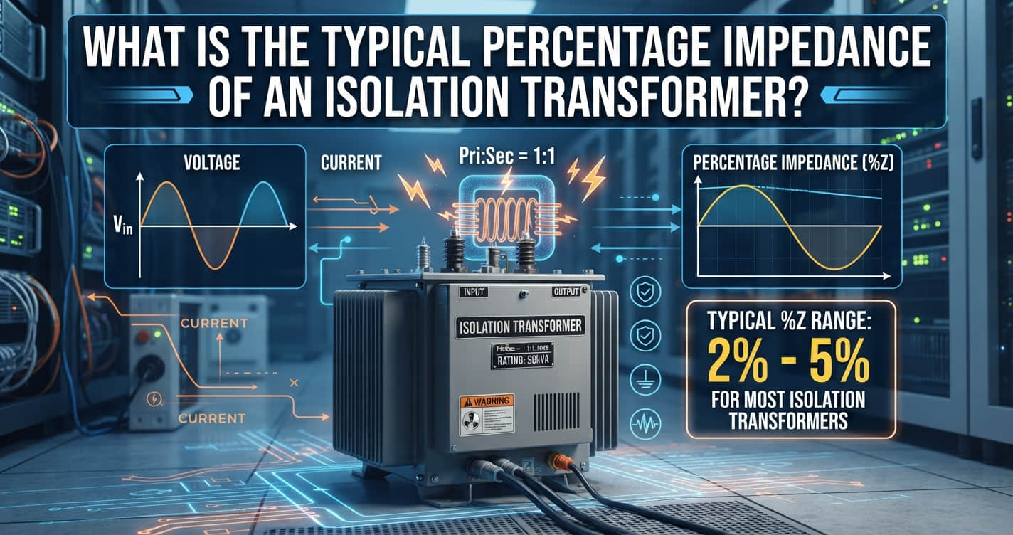
As a practical guide, lower-capacity isolation transformers are often seen around 1% to 4%. Medium-power distribution isolation transformers are commonly around 2% to 6%. Larger power units may be higher than medium-power designs, especially when system fault current must be controlled.
But those are not guaranteed rules. They are only common engineering patterns. On an actual project, the required impedance must be confirmed from the approved technical specification, nameplate data, and manufacturer test documents.
Why There Is No Single Standard Impedance Value
If you have worked on transformer procurement, you already know the real answer never comes from a random internet number. It comes from the application.
Impedance is selected to balance several design goals that often compete with each other.
Short-circuit current limitation: Higher impedance reduces available fault current.
Voltage regulation: Lower impedance can help reduce load-side voltage drop.
Thermal design: Winding geometry, conductor size, and losses interact with impedance choice.
Noise control: Core and coil mechanical design linked to impedance can affect sound levels.
Protection coordination: The chosen impedance must work with breaker settings and system fault studies.
Customer specification: Some buyers explicitly require a narrow impedance band.
That is why experienced engineers do not ask, “What is the one normal value?” They ask, “What impedance does this system require?”
For example, a hospital clean power application, a commercial building distribution transformer, and a heavy industrial drive system may all use isolation transformers of similar voltage class, yet they may need very different impedance targets.
In practice, manufacturers such as Weisho Electric often review the complete duty conditions before confirming the final design. That is the correct approach, because the same kVA rating alone does not tell the full story.
Typical Transformer Impedance Range by Isolation Transformer Size
Instead of forcing one universal value, it is more useful to look at practical ranges by power class.
These ranges are common market observations and project tendencies, not mandatory standards.
Small Power Isolation Transformer: About 1% to 4%
For smaller isolation transformers, especially low-kVA units used in control circuits, instrumentation, machine tools, medical auxiliary circuits, or sensitive equipment isolation, the typical transformer impedance range is often on the lower side.
In many cases, you may see values around 1% to 4%. Lower impedance can support tighter voltage regulation under changing loads, which is useful where equipment performance is sensitive to voltage drop.
That said, not every small transformer will sit neatly in this band. A compact design with specific thermal or fault-duty requirements may be above or below that general range.
Medium Power Distribution Isolation Transformer: About 2% to 6%
For medium-capacity distribution-grade isolation transformers, a broader range is common. Many practical designs fall around 2% to 6%.
This is often where engineers start balancing multiple real-world factors at once: acceptable voltage drop, manageable short-circuit current, heat performance, enclosure limits, and system protection coordination.
Commercial buildings, data support areas, manufacturing panels, and secondary distribution networks often fall into this category.
Large Power Isolation Transformer: Often Higher Than Medium-Power Designs
As transformer size increases, impedance is often selected at higher values than medium-power units.
The reason is straightforward. Larger transformers can contribute very high fault currents if impedance is too low. In industrial plants and large facilities, the upstream and downstream switchgear interrupting capacity may force designers to choose higher impedance to keep fault current within safe limits.
Large units also face stronger mechanical stress during fault events. A higher impedance selection may be part of the broader strategy to protect the transformer and connected equipment.
Again, there is no fixed number. The final value depends on the project study, not assumptions.
Real-World Typical Transformer Impedance Ranges by Capacity
The table below gives a practical reference for isolation transformer percentage impedance by capacity band. These are market-based engineering examples, not universal standards.
| CAPACITY RANGE (KVA) | TYPICAL ISOLATION TRANSFORMER PERCENTAGE IMPEDANCE | TYPICAL USE CASE | DESIGN NOTE |
|---|---|---|---|
| 0.05 to 1 kVA | About 1% to 3% | Control circuits, instrumentation, PLC auxiliary supply | Often optimized for compact size and stable secondary voltage under light to moderate load variation |
| 1 to 10 kVA | About 1.5% to 4% | Machine isolation, laboratory equipment, small medical support loads | Lower impedance is common, but thermal rise and enclosure size still matter |
| 10 to 75 kVA | About 2% to 5% | Small distribution isolation, commercial subpanels, sensitive equipment rooms | Often a compromise between regulation and fault-current control |
| 75 to 500 kVA | About 2.5% to 6% | Commercial buildings, data support systems, light industrial distribution | Protection coordination becomes more important in this band |
| 500 to 2500 kVA | Often 4% to 8% or project-specific | Large industrial feeders, process plants, heavy-duty building services | Higher impedance may be selected to reduce short-circuit duty on switchgear |
| Above 2500 kVA | Frequently higher and strongly project-dependent | Large industrial isolation, utility interface, high fault-level systems | Must be confirmed by system study, specification, and manufacturer design review |
Notice the pattern: capacity increases, project constraints increase, and impedance selection becomes less generic.
What Percentage Impedance Means in a Transformer
A lot of confusion disappears once transformer impedance voltage explained is presented in simple language.
Percentage impedance is the percentage of rated voltage required to circulate rated current in the transformer when the secondary is short-circuited during the standard test condition.
That sounds technical, but the idea is practical.
If a transformer has a lower percentage impedance, it takes less applied voltage to push rated current under short-circuit test conditions. In a real power system, that usually means the transformer can allow a higher short-circuit current.
If the transformer has a higher percentage impedance, it resists fault current more strongly. That usually lowers the available short-circuit current seen by downstream devices.
This is why isolation transformer short-circuit impedance is not just a test-lab number. It directly affects system protection and equipment duty.
How to Calculate Transformer Percent Impedance
For engineers, buyers, and maintenance teams, the basic formula is straightforward.
Basic Formula
Percent impedance = (impedance voltage / rated voltage) × 100
This is the standard answer to the search query how to calculate transformer percent impedance.
For example, if a transformer rated primary voltage is 400 V, and 16 V is required during the short-circuit test to produce rated current, then the percent impedance is:
(16 / 400) × 100 = 4%
That is the test concept in its simplest form.
Related Project Check
In the field, never rely only on a theoretical calculation or catalog memory.
Before purchase or installation, confirm:
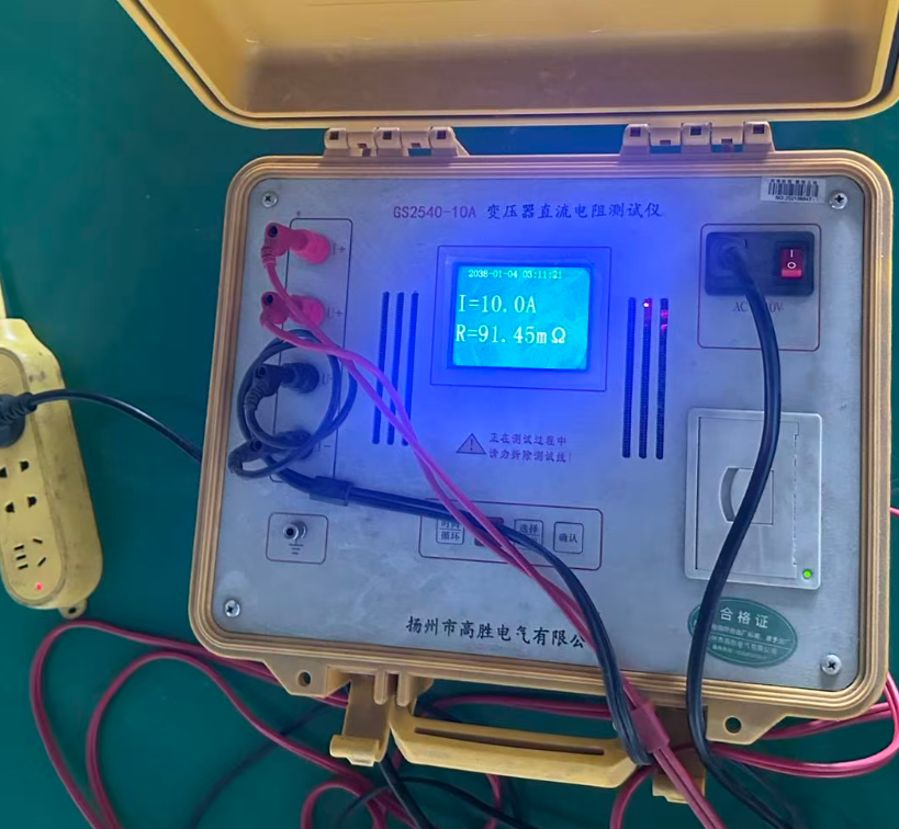
Nameplate impedance value
Routine test report or type test data
Approved project specification
Voltage class and tap arrangement
Frequency and load profile
Experienced project teams treat those documents as mandatory, especially when fault level is close to switchgear ratings.
Why Transformer Impedance Matters in Real Projects
On paper, impedance looks like one line item. On site, it affects system behavior every day.
It influences protection performance, voltage stability, heat, and sometimes even what people hear standing next to the unit.
Impact on Short-Circuit Current
This is the most immediate and most critical effect.
Lower impedance increases available fault current. Higher impedance helps limit it.
That matters because circuit breakers, busbars, cables, and switchboards all have short-circuit withstand and interrupting ratings. If a transformer is selected with lower impedance than the system study assumed, the available fault current may exceed equipment capability.
In one real industrial retrofit case, a plant replaced an older 1000 kVA transformer with a lower-impedance unit to improve voltage performance on motor starts. The result was an increase in prospective fault current large enough to trigger a switchgear review, because the downstream panel rating margin became too tight.
That is why impedance must be coordinated with protection devices, not chosen in isolation.
Impact on Temperature Rise
Impedance is not a standalone heat number, but it interacts with the winding and loss design that shapes thermal performance.
To achieve a particular impedance target, the manufacturer may adjust winding spacing, conductor arrangement, leakage flux path, and physical geometry. Those choices influence losses and hot-spot behavior.
A transformer with a project-specific impedance requirement may therefore need a different copper cross-section, different insulation margins, or a different cooling strategy to maintain acceptable temperature rise.
So when people ask whether transformer impedance affects heat, the accurate answer is yes, but not by a single direct one-variable rule. It is part of the larger electromagnetic and thermal design.
Impact on Noise
Noise is another area where simplistic answers cause trouble.
Impedance alone does not determine transformer sound level. However, the structural and magnetic design decisions used to reach a target impedance can influence vibration and acoustic performance.
For example, changes in winding arrangement, clamping structure, leakage flux management, and core-coil mechanical stiffness can all affect how much audible hum or vibration the transformer produces.
In office buildings, hospitals, studios, and high-end commercial spaces, this matters more than many buyers expect.
That is why project specifications often combine impedance requirements with a sound limit in dB.
Impact on Voltage Regulation
Impedance affects load-side voltage drop.
Generally speaking, a lower-impedance transformer tends to have better voltage regulation under load, while a higher-impedance transformer can introduce more voltage drop at higher current.
This matters when feeding sensitive electronics, long cable runs, variable loads, or motors with strict starting performance requirements.
There is always a tradeoff. Better fault current limitation often means more voltage drop. Better voltage regulation often means higher fault current. Good transformer selection is the art of balancing both.
Example Fault Current Effect at Different Transformer Impedance Values
The following example uses the same transformer rating and voltage, changing only the impedance. It shows why lower impedance raises fault current.
Assume a 1000 kVA, 400 V transformer. Full-load current is approximately 1443 A.
Approximate secondary short-circuit current at transformer terminals can be estimated as:
Short-circuit current ≈ Full-load current ÷ (Z% / 100)
| TRANSFORMER RATING | VOLTAGE | % IMPEDANCE | APPROX. SHORT-CIRCUIT CURRENT | ENGINEERING TAKEAWAY |
|---|---|---|---|---|
| 1000 kVA | 400 V | 2% | About 72,150 A | Very high fault current; switchgear duty rises sharply |
| 1000 kVA | 400 V | 4% | About 36,075 A | Fault current is roughly half of the 2% case |
| 1000 kVA | 400 V | 5% | About 28,860 A | Often easier to coordinate with common LV equipment ratings |
| 1000 kVA | 400 V | 6% | About 24,050 A | Further reduction in fault duty, but load voltage drop must be reviewed |
| 1000 kVA | 400 V | 8% | About 18,038 A | Stronger fault-current limitation, but system performance tradeoffs increase |
These values are simplified terminal estimates and do not replace a full short-circuit study. Cable impedance, upstream source strength, motor contribution, and network topology all matter.
Still, the trend is clear and very important in design meetings.
Real-World Examples of Isolation Transformer Impedance Selection
Here is where theory becomes procurement reality.
The final impedance value must match the actual installation.
Example 1: Small Control Isolation Transformer
Consider a 1 kVA isolation transformer used in a machine control cabinet with a 400 V primary and 230 V secondary feeding relays, contactors, a PLC power supply, and low-power control devices.
In this type of application, a lower impedance design may be desirable to minimize voltage drop during control inrush events, especially if several contactor coils pull in simultaneously.
A unit around the lower practical range may perform well here, provided the protective device coordination is still acceptable.
If the buyer simply assumes a higher generic impedance without checking operating behavior, nuisance undervoltage issues may appear at the secondary.
Example 2: Medium Distribution Isolation Transformer for Commercial Facility
Now consider a 250 kVA isolation transformer feeding a commercial tenant distribution board in a mixed-use building.
The engineering team wants stable voltage, but the available fault level at the downstream panel must also remain within the interrupting capacity of installed breakers.
This is where a mid-range impedance selection often makes sense. Too low, and fault duty rises. Too high, and voltage drop becomes more noticeable during HVAC cycling or elevator support loads.
On this kind of project, the “best” value is usually the one that came out of the short-circuit and voltage-drop study, not the cheapest catalog option.
Example 3: Large Industrial Isolation Transformer
Take a 2000 kVA industrial isolation transformer in a plant with large motors, MCC sections, and high available source fault current from the utility.
Here, the engineering priority may shift toward limiting short-circuit current to protect low-voltage switchgear and maintain coordinated protection operation.
A higher impedance design than the medium-power norm may be selected deliberately. That choice can reduce fault stress on downstream equipment and may avoid expensive switchgear upgrades.
However, the team must then review motor starting voltage dip, thermal behavior, and operational margins carefully.
This is exactly the kind of project where a manufacturer with practical application support, such as Weisho Electric, adds value beyond simply quoting a kVA and price.
How to Specify Isolation Transformer Impedance Correctly
If you are preparing a purchase specification, a consultant design package, or an EPC bid document, do not leave impedance vague.
Use a checklist.
Confirm kVA, Voltage Ratio, and Frequency
Start with the fundamentals.
Confirm:
Rated kVA
Primary voltage
Secondary voltage
Phase configuration
Frequency
Tap requirements
Without these basics, the impedance discussion is incomplete.
Confirm Required Percent Impedance
Do not assume the manufacturer will guess correctly.
The required percent impedance should be stated in the project specification or explicitly confirmed during technical clarification. If a range is acceptable, that range should be documented.
This is especially important when multiple bidders are involved. Otherwise, one vendor may price a lower-impedance design and another may quote a higher-impedance design, and the offers will not be technically equivalent.
Confirm Short-Circuit Study and Protection Coordination
This step is too often skipped on smaller jobs and regretted later.
Confirm that the transformer impedance used in the short-circuit study matches the actual transformer offered. Then verify breaker interrupting ratings, relay settings, fuse curves, and coordination margins.
This is also the right point to review related protection hardware such as the breaker trip system.
Confirm Thermal, Noise, and Installation Requirements
Do not stop at fault current.
Also confirm:
Temperature rise class
Insulation class
Ambient temperature
Altitude
Indoor or outdoor installation
Enclosure or IP rating
Permitted sound level
Ventilation conditions
Many transformer disputes start because the team focused only on electrical rating and ignored installation reality.
Isolation Transformer Impedance vs. Short Circuit Impedance: Are They the Same?
In most transformer discussions, yes, they refer to the same basic tested concept.
When people say isolation transformer short circuit impedance, they are usually talking about the impedance determined from the short-circuit test and expressed as a percentage of rated voltage.
Different engineers may use slightly different wording:
Percent impedance
Impedance voltage
Short-circuit impedance
%Z
In practical specification work, these are closely related ways of describing the same rated performance parameter. The key is to confirm the exact test basis and documentation used by the manufacturer.
Related Protection Topic: How Shunt Trip Works with Transformer-Fed Systems
Many users searching for transformer impedance are also dealing with breaker protection and remote tripping.
That connection is logical. Once impedance affects fault current, the next question is often how the breaker will respond.
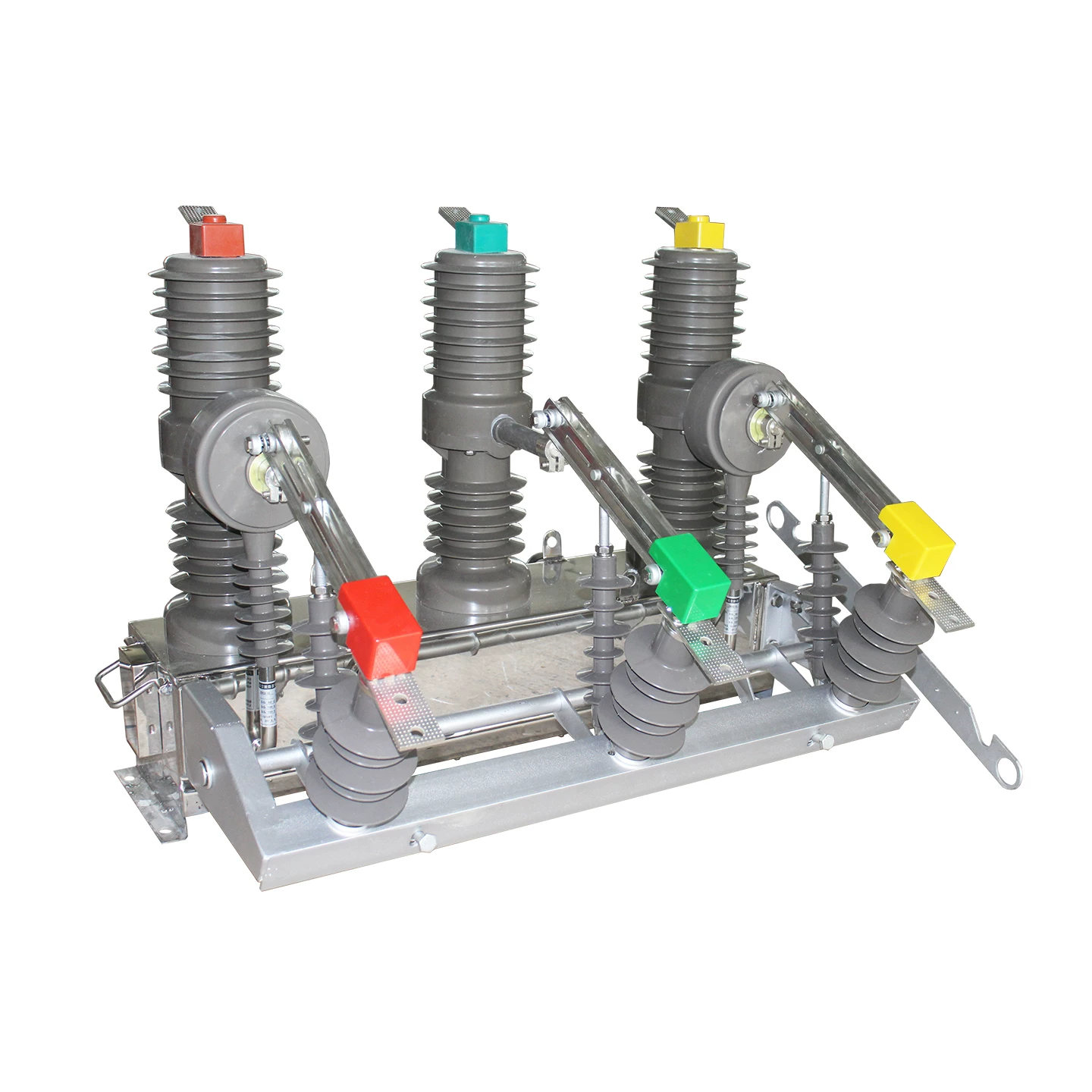
What Is a Shunt Trip Coil in a Vacuum Circuit Breaker?
A shunt trip coil in vacuum circuit breaker applications is an electrically operated trip device that opens the breaker remotely when energized.
It is commonly used in transformer protection schemes, emergency shutdown circuits, fire alarm interface logic, and relay-based fault isolation systems.
How a Shunt Trip Mechanism Works
If you are asking how a shunt trip mechanism works, the operating principle is straightforward.
When the shunt trip coil receives its control voltage, it releases the breaker’s trip latch. That mechanical release causes the breaker contacts to open.
This gives the system a remote trip function in circuit breakers without requiring a person to manually operate the breaker.
Vacuum Circuit Breaker Tripping Operation in Transformer Protection
Vacuum circuit breaker tripping operation is especially important in medium-voltage transformer installations.
Protection relays monitor current, differential behavior, earth fault conditions, temperature alarms, or other abnormal signals. If a transformer fault is detected, the relay sends a trip command to the breaker, and the shunt trip coil opens the circuit.
This rapid disconnection helps limit damage to the transformer and protects the wider system.
Remote Trip Function in Circuit Breakers
The remote trip function in circuit breakers is widely used in modern facilities.
Typical applications include:
Emergency stop systems
Fire alarm shutdown interfaces
BMS or SCADA commands
Protective relay outputs
Interlock logic for unsafe operating conditions
In transformer-fed systems, this function allows fast isolation when abnormal current or thermal conditions occur.
Electrical Protection Using a Shunt Trip Breaker
Electrical protection using shunt trip breaker arrangements is a practical way to isolate transformer faults and support coordinated protection design.
The breaker itself does not replace proper impedance selection. Instead, it works together with the transformer design, fault study, relay settings, and installation practice.
If the transformer impedance is wrong for the system, even the best breaker scheme may face unnecessary stress. Good protection starts with correct transformer specification.
Common Mistakes When Choosing Transformer Impedance
Most field problems come from a few repeatable mistakes.
Avoid them early.
Assuming One “Typical” Value Fits All Projects
This is the biggest error.
There is no universal standard number that applies to every isolation transformer. Anyone selecting a transformer by copying one generic internet value is taking a risk.
Small units may commonly be around 1% to 4%. Medium distribution units may commonly be around 2% to 6%. Large units may go higher. But even those ranges must be checked against the project specification.
Ignoring Fault Current Levels
This mistake can become expensive very quickly.
If the selected impedance is too low, the available fault current may exceed the breaker interrupting capacity or the busbar short-time withstand rating. That can trigger redesign, equipment replacement, or safety concerns.
Always compare transformer impedance assumptions against the latest short-circuit study.
Overlooking Temperature Rise and Noise Limits
Some teams focus only on fault current and forget operational performance.
But real installations also care about:
Winding temperature rise
Hot-spot margin
Ventilation limits
Acoustic performance
A technically acceptable impedance on paper may still be the wrong choice for a noise-sensitive building or a hot electrical room.
Failing to Confirm Manufacturer Test Data
Catalog assumptions are not enough.
Always request and confirm:
Nameplate data
Routine test reports
Approved GA drawings
Electrical schematic details if applicable
Guaranteed technical particulars
That is how you verify the offered unit actually matches the design intent.
FAQ
What is the typical percentage impedance of an isolation transformer?
There is no single fixed value for all isolation transformers. In practical terms, small power units are often around 1% to 4%, medium power distribution isolation transformers commonly fall around 2% to 6%, and larger units are often higher depending on fault-current limits, design goals, and customer requirements. The exact impedance must always be confirmed by project specification and manufacturer documentation.
Is there a standard isolation transformer impedance value?
No. There is no single universal impedance value across all isolation transformers. The final value depends on transformer capacity, voltage class, winding design, thermal target, voltage regulation needs, short-circuit duty, acoustic constraints, and customer specification.
What is a normal transformer impedance range for small, medium, and large units?
A practical field reference is this: small power isolation transformers are often around 1% to 4%, medium distribution isolation transformers are often around 2% to 6%, and large power units may be higher than medium-power designs. These are not mandatory rules, only common ranges that must be validated for the actual project.
How does transformer impedance affect short-circuit current?
Lower impedance means higher available short-circuit current, while higher impedance helps limit fault current. This is why transformer impedance has a direct influence on breaker interrupting duty, busbar stress, and protection coordination.
How do you calculate transformer percent impedance?
The basic formula is: percent impedance = (impedance voltage / rated voltage) × 100. In practice, engineers should also verify the value using the transformer nameplate and routine test report, rather than relying only on a theoretical calculation.
Does higher transformer impedance reduce noise?
Not by itself. Noise is not determined by impedance alone. However, the core and winding design choices associated with a particular impedance target can influence vibration and acoustic behavior, so impedance-related design decisions may affect sound level indirectly.
Does transformer impedance affect temperature rise?
Yes, but indirectly through the overall electromagnetic and thermal design. Winding arrangement, conductor sizing, leakage flux path, and losses all interact with impedance, so the selected impedance can be relevant to temperature rise and hot-spot performance.
Should I confirm impedance before ordering an isolation transformer?
Absolutely. The project team should always verify the required impedance in the technical specification, short-circuit study, approved drawings, nameplate details, and manufacturer test documents before ordering or installing the transformer.
Conclusion: Confirm the Required Transformer Impedance for Your Project
The most important takeaway is this: isolation transformer impedance is not one fixed percentage.
There is no honest engineering answer that gives one universal value for every project. Small power isolation transformers may commonly be in the 1% to 4% range. Medium distribution units may often be in the 2% to 6% range. Large power units are often higher. But the exact value always depends on capacity, design, and customer specification.
And that value matters.
It affects short-circuit current, temperature rise, voltage regulation, and noise. It also influences protection coordination, breaker selection, and the long-term reliability of the installation.
So if you are selecting an isolation transformer, do not ask only for kVA and voltage. Ask for the percent impedance, ask how it was selected, and ask for the supporting test data.
That is how sound projects avoid expensive surprises.
CTA: Need Help Selecting the Right Isolation Transformer Impedance?
If you are sizing a transformer now, do not rely on a generic number copied from a catalog or website.
Send your kVA, primary and secondary voltage, frequency, available fault level, load type, ambient condition, enclosure requirement, and noise limit. With those details, a proper technical review can identify the right transformer impedance for your application.
Whether your project is a small control panel, a commercial distribution upgrade, or a large industrial installation, the safest path is to confirm the impedance before ordering.
Contact us now for a matched recommendation, technical review, and specification support for your isolation transformer project.