Author: Thor, 12-Year Electrical Engineer, Affiliation: Weisho Electric Co., Ltd.
In the world of electrical power, current and voltage are the most fundamental parameters. Have you ever wondered how we safely and accurately measure them in a high-voltage environment?
The answer lies with two critical devices: Current Transformers (CTs) and Voltage Transformers (VTs). While both are indispensable components of any power system, they have essential differences in function, principle, and application.
This guide provides a comprehensive overview of the key differences between CTs and VTs. We’ll cover everything from their basic definitions and working principles to real-world applications, helping you make the right decisions when selecting and using them.
Part 1: Core Concepts & Working Principles
The Current Transformer (CT): A Current Scaler
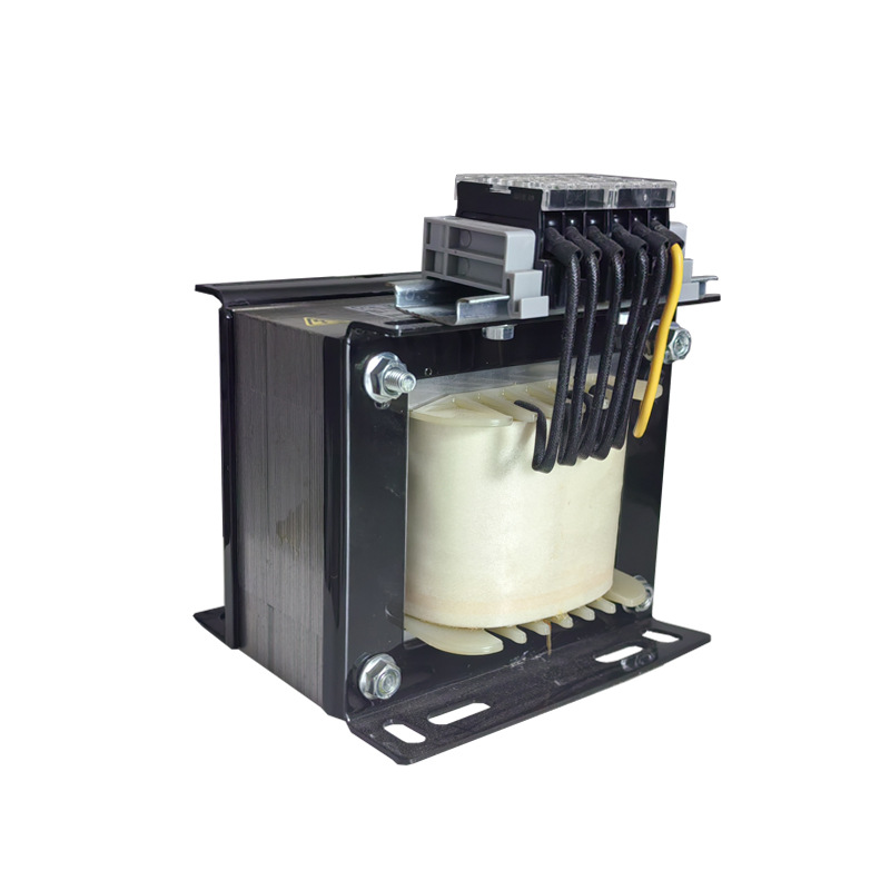
A Current Transformer (CT) is a device used to transform a large primary current into a standardized, low-level secondary current, typically 5A or 1A. Its primary functions are current measurement and overload protection.
The CT's primary winding is connected in series with the main circuit. This allows the high current to flow through a single or very few turns. This then induces a proportionally smaller current in the multi-turn secondary winding.
A critical point to remember is that a CT's secondary side must never be operated in an open circuit. When the secondary is open, the high primary current serves as a source for excitation, which can induce a dangerously high voltage on the secondary side. This risks personal injury or equipment damage.
The Voltage Transformer (VT): A Voltage Sentinel
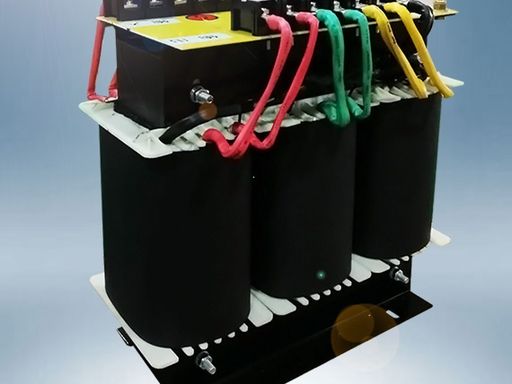
A Voltage Transformer (VT), also known as a Potential Transformer (PT), is designed to step down high voltages to a standardized, low-level secondary voltage, typically 100V or 110V. Its main purposes are voltage measurement and over-voltage protection.
A VT is a specialized transformer with a structure and application that are both highly specific. Its primary winding is connected in parallel with the circuit.
The VT’s secondary current is determined by the impedance of the connected load. As the secondary load impedance decreases, the secondary current increases to maintain the electromagnetic balance between the primary and secondary sides.

Part 2: Core Differences & Comparison
Although both CTs and VTs operate on the principle of electromagnetic induction, their internal magnetic structure and operational states under normal conditions are vastly different. This is their most fundamental distinction.
From a power source perspective, a VT's primary side can be considered a voltage source with very low internal impedance. Its output voltage is largely unaffected by the secondary load.
A CT's primary side, on the other hand, can be considered a high-impedance current source. Its output current is essentially independent of the secondary load.
During normal operation, a VT's magnetic flux density approaches the saturation point. However, when a fault occurs, the voltage drops, and the magnetic flux density decreases.
In contrast, a CT's magnetic flux density is quite low under normal conditions. During a short circuit, the flux density increases dramatically and can even exceed saturation levels.
This leads to their most crucial difference in operation: a CT's secondary can be shorted but must never be open. A VT's secondary can be open but must not be shorted.
Part 3: Practical Applications & Insights

The Diverse Family of Instrument Transformers
In real-world engineering, instrument transformers come in various forms to suit different applications.
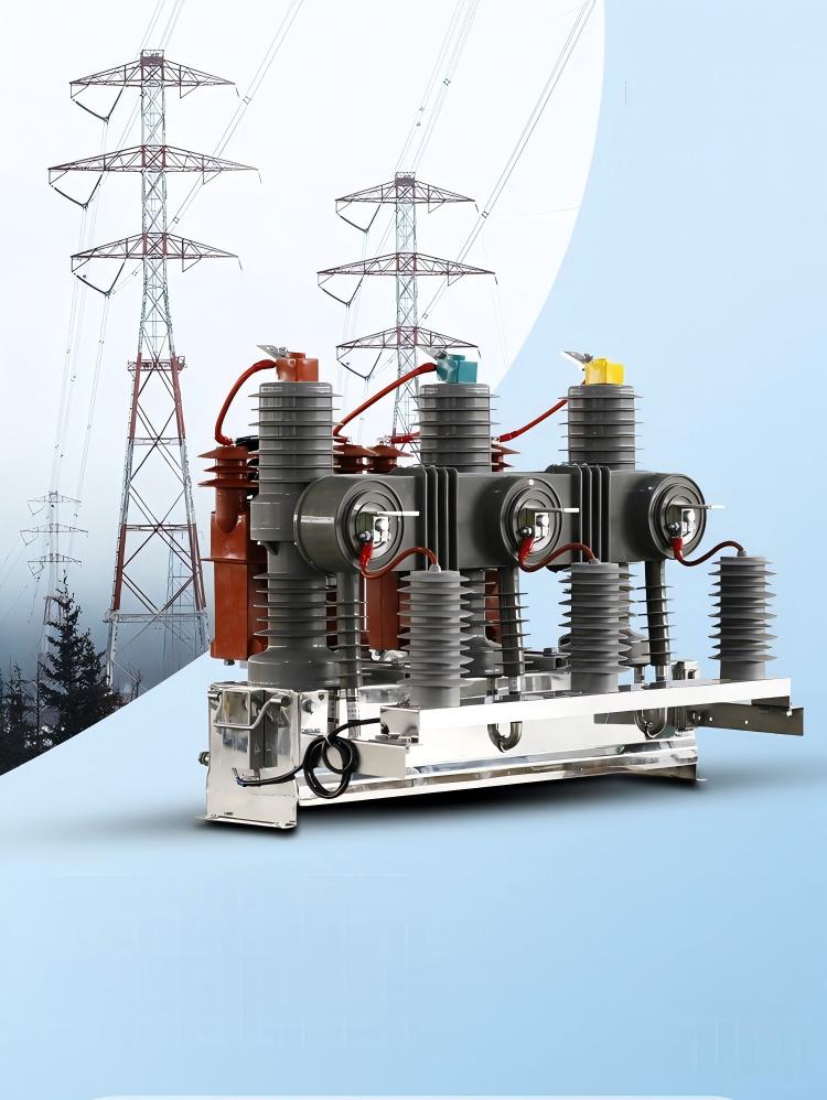
CT Types: The most common types are the Wound Type, where both primary and secondary windings are wrapped around the core. There are also Bushing Type CTs, which are mounted on a transformer or switchgear bushing and have no separate primary winding. The Core-balance CT is used for ground fault protection by detecting unbalanced currents.
VT Types: The Capacitive Voltage Transformer (CVT) is specifically used in ultra-high voltage systems of 220kV and above. It uses a capacitance divider principle to step down the voltage. CVTs can also be used for power line carrier communication.
Protection & Metering: A Dual Mission
CTs and VTs are the cornerstones of safety in a power system. They provide accurate signals to protective relays and metering systems.
When a fault like a short circuit or overload occurs, they quickly capture the abnormal signal. This allows the relay to trip the circuit breaker in milliseconds and prevent catastrophic damage.
For commercial power metering, CTs and VTs safely route the high-voltage current and voltage signals to the energy meters. This ensures accurate billing for the electricity consumed.
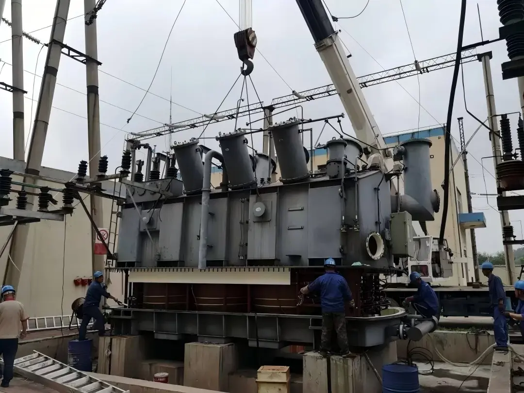
Case Study: A 230kV U.S. Transmission Substation
In a 230kV substation in the Texas power grid, serving a major semiconductor manufacturing plant, engineers deployed numerous CTs and VTs to ensure a stable supply. CTs (2500:5A) were installed on the substation busbars and outgoing transmission lines to monitor the primary current. Their secondary signals fed power meters for precise billing and differential protection relays to instantly isolate faults.
VTs (230kV:115V) were connected in parallel on the busbars. Their secondary signals were used for grid synchronization to ensure new generators could connect safely. They also provided data for fault localization by detecting voltage drops. CTs and VTs work together to provide continuous data for load management and to protect the grid from disturbances like lightning strikes or line shorts.
Part 4: The Expert's Take
In-Depth Standards & Parameters
For professionals, selecting the right instrument transformer means understanding its accuracy and protection classes. These are defined by international standards like
For metering purposes, a highly accurate CT is needed, typically with a 0.2S or 0.5 class. The "S" signifies superior accuracy at low current levels, which is crucial for precise billing.
For protection, you'll choose a CT with a 5P or 10P class. The "P" stands for protection. These CTs must maintain accuracy at several times the rated current to ensure the protective relay receives a reliable signal during a fault.
Troubleshooting & Safety Tips
This is an unwritten rule among field engineers: Never open a CT's secondary circuit while the primary is energized. The resulting voltage spike can be lethal. If you need to service a CT, always short its secondary terminals first to create a safe, zero-voltage path. This simple step is a mark of an experienced and trustworthy engineer.

Part 5: Future Trends
The power industry is evolving, and so are instrument transformers. We are moving away from traditional iron-core devices toward next-generation solutions.
Low-Power Instrument Transformers (LPITs): These devices use fiber optics and electronics. They offer superior accuracy, a smaller size, and enhanced safety by eliminating the need for a metallic secondary circuit.
The Digital Substation: LPITs are central to the new
IEC 61869-6 standard . This standard enables a fully digital substation where instrument transformers no longer just output an analog signal. They communicate a data stream of voltage and current values directly to the control room, revolutionizing how we monitor and protect the grid.
Frequently Asked Questions (FAQ)
Which is more expensive, a CT or a VT?
Generally, VTs tend to be more expensive than CTs of a similar voltage class. This is due to the higher manufacturing cost of their multi-turn primary windings and more rigorous insulation requirements. In ultra-high voltage systems, a Capacitive Voltage Transformer (CVT) can be even more expensive.
How do I correctly choose the ratio and accuracy of a transformer?
The ratio depends on the primary circuit's rated current or voltage. The accuracy depends on the purpose: for billing, choose a high-accuracy class like 0.2S or 0.5. For protection, choose a 5P or 10P class to ensure accuracy during faults.
What are the wiring rules for CT and VT secondary terminals?
A CT's secondary terminals must be grounded to prevent high voltage from the primary side from inducing a hazardous voltage. It must also remain a closed circuit. A VT's secondary terminals must also be grounded.
What is the recommended maintenance schedule for CTs and VTs?
It's generally recommended to perform an annual visual inspection. This includes checking for cracks, signs of discharge, and ensuring terminals are tight. A more comprehensive electrical test, such as an insulation resistance test, should be performed every 3-5 years.
What are the most common faults with instrument transformers?
The most common faults are an open secondary circuit (for CTs), insulation degradation or aging leading to partial discharge, and winding damage from overload or short circuits.
Get Professional Support & Contact Us
Hopefully, this guide has given you a comprehensive understanding of these two vital instrument transformers. If you have any questions about product selection, technical specifications, or project applications, our team of experts is ready to assist you.
Please feel free to leave a message or send us an email. Our experts are dedicated to providing you with professional support.
Weisho Electric Co., Ltd.
📞 Phone: +86-0577-62788197
📱 WhatsApp: +86 159 5777 0984
✉ Email: [email protected]
🌐 Website: weishoelec.com