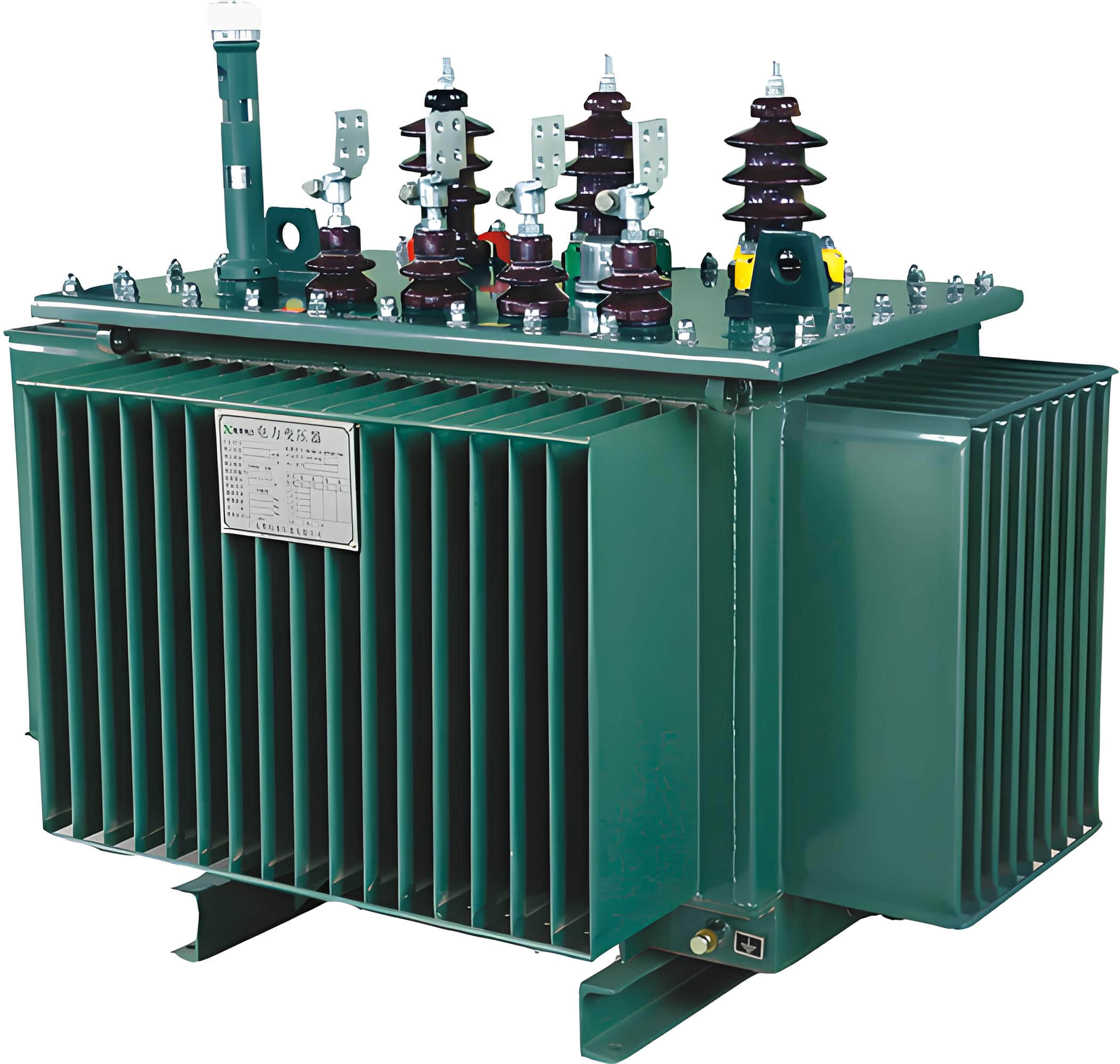
A potential transformer (PT) is a device that safely converts high voltage into low voltage for easier measurement and protection in electrical systems. Knowing how PTs work helps you better monitor and protect electrical equipment.
While working at Wei Shoe Elec, I met many people confused about PTs. They often looked just like regular transformers. I had the same doubts early on, but everything changed once I saw how PTs performed in real systems. I then realized how important it is to choose the right PT for accurate readings and reliable protection.
In this article, I’ll walk you through how PTs work, how to read their wiring diagrams, and how to avoid common mistakes in selection and wiring. Let’s make this technical topic simple, practical, and even interesting.
How a Potential Transformer Works
A PT reduces high voltage to a lower, safer level for measurement. It acts like a translator between powerful, dangerous voltage and the sensitive instruments you rely on.
Here’s how it works:
Input (Primary side): The PT connects to the high-voltage part of the system.
Output (Secondary side): It lowers the voltage, for example, from 11,000 volts to 110 volts.
Purpose: This low voltage can be safely used by meters and relays.
Think of a PT like a filter on a camera lens. The filter protects your eyes from the sun while still letting you see clearly. In the same way, a PT brings dangerous voltage down to a level instruments can safely “see.”

Key Features of a Potential Transformer
PTs are designed with precision and safety in mind:
High Accuracy: They are made to be extremely accurate, with very low error.
Fixed Ratio: They convert voltage at a set ratio, like 100:1.
Electrical Isolation: They isolate measuring devices from high voltage, making it safer.
For example, in U.S. industrial substations, the voltage can be 13.8 kV. A PT reduces it to 120 V, so voltage relays can read it. This lets the control system make safe and accurate decisions.

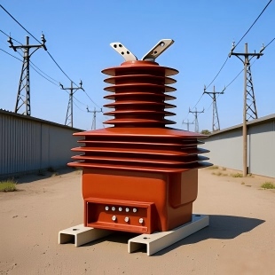
Detailed Working Principle of a PT
PTs work based on electromagnetic induction. They are similar to regular transformers but focus on accurate voltage measurement, not power transfer.
The high voltage passes through the primary coil. This creates a magnetic field, which then induces a voltage in the secondary coil. The PT lowers the voltage at a fixed ratio so meters and relays can read it safely.
It’s like using a pressure reducer on a fire hose. You wouldn’t let high-pressure water hit a fragile device directly—you need to lower the pressure first.
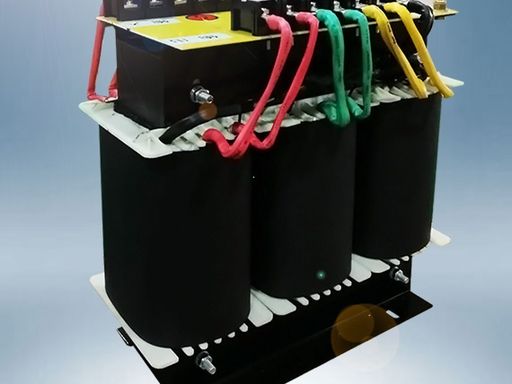
PTs usually use oil or epoxy resin insulation. They also contain built-in fuses to prevent damage, ensuring safety and reliability.
PT vs CT: What's the Difference?
PTs are often confused with current transformers (CTs), but they serve very different purposes.
Feature | Potential Transformer (PT) | Current Transformer (CT) |
Measures | Voltage | Current |
Primary Connection | Parallel to the line | In series with the load |
Output | Low voltage (e.g., 110 V) | Low current (e.g., 5 A) |
Purpose | Voltage measurement/protection | Current measurement/protection |
For instance, in a substation, PTs monitor bus voltage while CTs measure the current of each outgoing line.

How to Read a PT Wiring Diagram
Understanding PT diagrams helps with installation and troubleshooting.
Here are common diagram elements:
Primary and Secondary Coils: Usually labeled as “H1, H2” for high voltage and “X1, X2” for low voltage.
Magnetic Core: Often shown as parallel lines.
Ground Symbol: One side of the secondary is grounded for safety.
Ratio Label: For example, 11,000 V / 110 V shows the voltage step-down.
Make sure the PT’s ratio matches your system voltage. A mismatch can lead to incorrect readings or even equipment failures.
Common Uses of a PT
PTs are widely used in the power industry:
Voltage Monitoring: Substations continuously track voltage and raise alarms during issues.
Relay Input: PTs feed voltage signals to relays, helping detect faults like overvoltage or undervoltage, which can trip breakers.
Billing Measurement: Accurate voltage readings help ensure fair electricity billing.
Power Quality Analysis: PTs supply real-time data to analyzers to detect problems like harmonics or voltage dips.
These uses help keep the power grid safe, efficient, and stable.

Installation and Troubleshooting Tips
Installation Tips:
Make sure the PT ratio matches the system voltage.
Properly ground the secondary side to avoid shock risks.
Add fuses to the secondary circuit to protect your instruments.
Keep wiring neat and short to reduce interference.
Common Troubleshooting Tips:
Strange Readings: Check if the ratio is correct.
No Output Voltage: Inspect fuses and secondary connections.
Excess Heat: May indicate an internal short—replace the PT.
Unstable Readings: Look for loose wires or nearby interference.
Regular checks and maintenance are key to preventing problems.

Frequently Asked Questions
Q1: Can a PT measure current?
No. PTs only measure voltage. Use a CT for current.
Q2: What happens if I wire a PT incorrectly?
It can give wrong readings, damage your instruments, or even cause safety risks.
Q3: Can PTs be used in DC systems?
No. PTs work only with AC, as they rely on electromagnetic induction.
Q4: How often should I test a PT?
Test it every 1 to 3 years, depending on the environment and importance of the system.
Conclusion
As a member of Wei Shoe Elec, I hope this article has helped you clearly understand what a potential transformer is, how it works, and why it’s important for voltage measurement and system protection. We explained complex concepts in simple language, showed how PTs differ from CTs, and offered practical installation and troubleshooting tips.
If you design, run, or maintain electrical systems, knowing how PTs work will save you time, reduce risk, and boost reliability.
Feel free to contact us for expert support, custom solutions, or a quote. Let’s keep your power system running safely and efficiently!