Common Applications and Use Cases
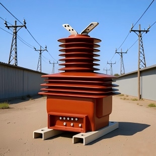
If you drive past overhead power lines and spot an electrical device hanging between the conductors that looks similar to a drop-out fuse, don’t be so quick to assume it’s a fuse. What you’re seeing is most likely a drop-out isolating switch.
These unassuming yet critical components play a vital role in our electrical infrastructure, quietly protecting transformers and other equipment while providing a clear, visible indication of circuit status. But what exactly are they, and why do electrical engineers consider them indispensable for certain applications?
Understanding the Basics of Electrical Isolation
Electrical isolation isn't just about turning something off—it's about creating a physical gap in a circuit that prevents current flow and ensures the safety of both equipment and personnel. In power distribution systems, isolation serves as the foundation for maintenance operations, equipment protection, and system reliability. Unlike circuit breakers that protect against overloads and faults, isolating switches create a visible break in the circuit that can be confirmed from a distance.
The principle is straightforward: when you need to work on electrical equipment, you want absolute certainty that power cannot reach that equipment. This is where visual confirmation becomes invaluable. A worker on the ground should be able to look up and see with their own eyes that the circuit is open, without relying on indicator lights or electronic displays that could malfunction.
Why Drop-out Isolating Switches Matter in Power Distribution
Drop-out isolating switches have earned their place in power distribution systems through decades of reliable service. They address a fundamental challenge: how do you provide safe, visible isolation at an affordable cost while maintaining system reliability? In rural electrical networks and distribution systems worldwide, these switches handle millions of operations annually, protecting transformers that serve homes, farms, and small businesses.
Consider this: according to industry data, properly maintained drop-out switches have failure rates below 0.5% annually, making them one of the most reliable components in distribution networks. Their simplicity translates to longevity, with many units remaining in service for 30 years or more. This reliability matters enormously when you're responsible for keeping the lights on across vast geographical areas with limited maintenance resources.
Who Uses These Switches and Where
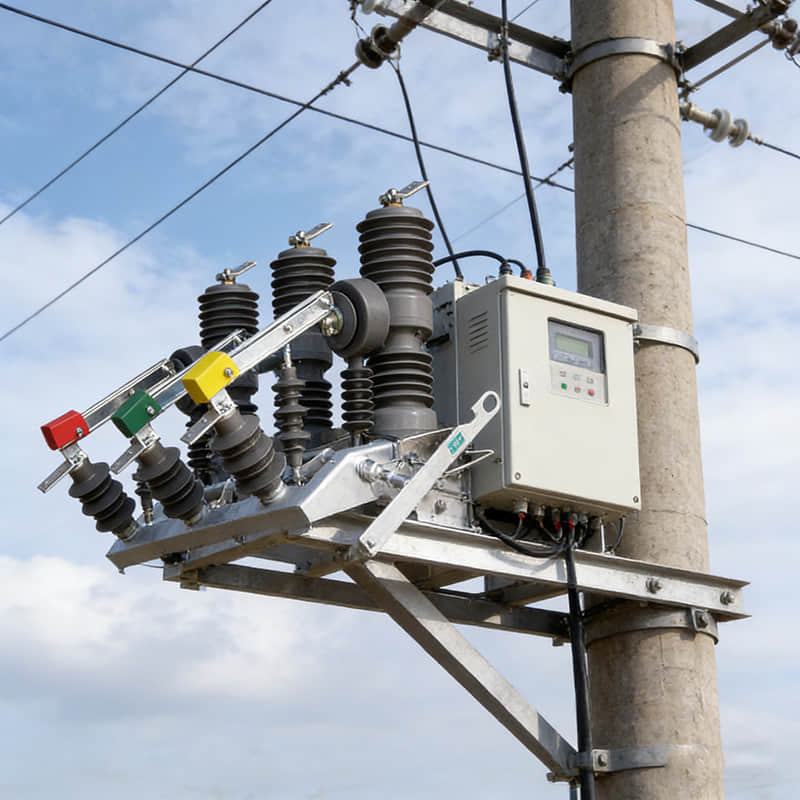
Utility companies are the primary users of drop-out isolating switches, particularly in medium-voltage distribution networks ranging from 11kV to 33kV. You'll find them mounted on poles throughout suburban and rural areas, protecting distribution transformers that step voltage down for residential use. Electrical contractors encounter them during service installations and maintenance operations, while industrial facilities use them for sectionalizing their internal distribution systems.
Mining operations, agricultural processing facilities, and manufacturing plants also rely on these switches for safe equipment isolation. Even in developing nations with growing electrical infrastructure, drop-out switches remain a cost-effective solution for expanding power networks where sophisticated switchgear might be economically prohibitive.
What Exactly is a Drop-out Isolating Switch?

Definition and Core Function
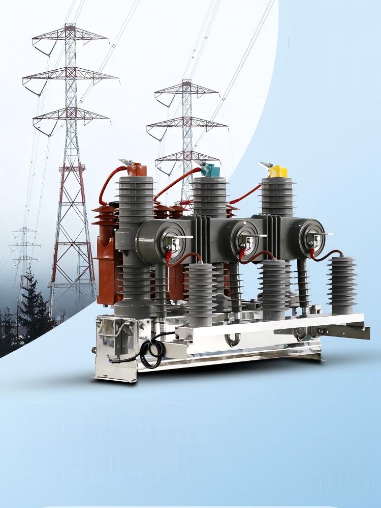
A drop-out isolating switch, often called a drop-out fuse or Solid-Link connection disconnect switch, is a combination protective and isolation device used primarily in overhead electrical distribution systems. At its core, it's a switch that opens automatically when a fault occurs or can be opened manually for maintenance purposes. The key distinguishing feature is its "drop-out" action—when the fuse element inside melts or when manually operated, the movable contact blade physically drops down due to gravity, creating a visible air gap between the line and load sides.
This device serves dual purposes: it acts as a fuse holder that protects downstream equipment from overcurrent conditions, and it functions as a visible isolating switch that can be operated manually with a hot stick (an insulated pole tool). The visual confirmation aspect cannot be overstated—a maintenance worker can immediately see whether the switch is open or closed without needing to test for voltage.
The "Drop-out" Mechanism Explained
The "drop-out" terminology comes from the switch's distinctive operating characteristic. Unlike conventional switches that might move sideways or rotate, these switches use gravity as their opening mechanism. The movable contact blade is held in the closed position by a latch mechanism. When a fault occurs and the fuse element melts, this latch releases, allowing the blade to swing downward under its own weight, typically rotating about a hinge point.
This gravity-assisted operation provides several advantages. First, it's inherently fail-safe—no spring mechanism can fail or lose tension over time. Second, the dropping action is highly visible, often accompanied by the blade hanging vertically downward, making the open status unmistakable even from ground level. Third, it requires no external energy source, making it completely passive and reliable.
Key Components and Design Features
A typical drop-out isolating switch comprises several essential components working in concert. The insulating body, usually made from high-grade porcelain or polymer materials, provides the structural foundation and electrical insulation from ground. Embedded within or attached to this body are the stationary contacts, typically made from copper or silver-plated materials to ensure good conductivity and corrosion resistance.
The movable blade assembly represents the heart of the mechanism. This blade connects the line side to the load side when closed and drops away when opened. Many designs incorporate a fuse holder that accepts standard expulsion fuse links—these are sacrificial elements that melt under fault conditions. The operating ring at the bottom of the blade allows utility workers to open and close the switch using a hot stick while remaining safely on the ground.
How It Differs from Regular Isolating Switches

Regular isolating switches typically require manual operation for both opening and closing, and they may not provide the same level of visible confirmation. A conventional knife switch, for example, might be housed in an enclosure where the contact position isn't immediately apparent. Drop-out switches, by contrast, offer what electrical engineers call "visual verification"—you can see the disconnection point.
Additionally, most drop-out switches integrate fuse protection directly into the isolation function, whereas standard isolators are purely mechanical disconnection devices with no overcurrent protection. This combination makes drop-out switches particularly economical for distribution applications where both functions are needed but separate devices would be cost-prohibitive.
The Anatomy of a Drop-out Isolating Switch
Main Contact Blades
The contact blade assembly is the most mechanically active component. Typically constructed from copper alloys for excellent conductivity, these blades are designed to carry continuous rated current without excessive heating. The blade features contact surfaces that may be silver-plated to reduce contact resistance and prevent oxidation. When closed, these contacts must maintain firm pressure against their mating surfaces to prevent arcing during normal operation.
The blade's physical design considers both electrical and mechanical requirements. It must be heavy enough to drop reliably under gravity when released, yet not so heavy that it causes excessive shock forces during drop-out. Many modern designs incorporate damping mechanisms to slow the final movement, reducing mechanical stress on the components.
Insulating Base and Support Structure
The insulating structure serves multiple critical functions. It must withstand the operating voltage between line and ground, resist tracking (the formation of conductive paths across the surface), and endure environmental stresses including UV radiation, temperature extremes, and contamination. Traditional porcelain insulators have been used for decades due to their excellent electrical properties and durability, though modern polymer insulators are increasingly popular for their lighter weight and resistance to vandalism.
The mechanical design includes mounting provisions, typically a crossarm attachment at the top that connects to the pole-mounted hardware. The structure must withstand mechanical loads from the conductors, ice and wind loading, and the dynamic forces generated during switching operations. Engineers specify these components based on the electrical rating and environmental conditions of the installation site.
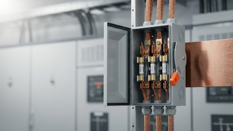
Fuse Holder Integration (Where Applicable)
In fused drop-out switches, the fuse holder is integrated into the blade assembly or positioned in series with it. This holder accepts expulsion fuse links, which consist of a fusible element inside a fiber tube. When fault current flows, the element melts and vaporizes, creating gases that blast out of the tube ends. This explosive expulsion helps extinguish the arc and provides a clear indication that the fuse has operated.
The fuse holder design must ensure reliable contact with the fuse link terminals while allowing for easy replacement. Standard fuse links come in various current ratings, allowing utilities to match the protection to the specific transformer or load being served. Some designs use universal holders that accept multiple fuse types, while others are specific to particular fuse families.
Operating Mechanism
The latch mechanism that holds the blade in the closed position represents clever mechanical engineering. It must hold securely during normal operation, withstanding vibration, wind-induced movement, and the electromagnetic forces generated during fault current flow. Yet it must release instantly when the fuse operates or when a utility worker pulls the blade open using a hot stick.
Most designs use a spring-loaded latch that engages with a catch on the blade. The fuse link completes a mechanical path that, when interrupted by fuse melting, triggers the latch release. Manual opening involves using the hot stick to pull on the operating ring, overcoming the latch force and allowing the blade to drop. The operating ring is typically positioned for easy access from ground level, though the exact height varies with pole-mounted configurations.
Arc Extinguishing Components
While drop-out switches aren't designed for breaking load current under normal circumstances, they must handle the arcing that occurs during fault interruption when the fuse operates. The expulsion fuse itself provides much of the arc-extinguishing capability—the rapidly expanding gases generated by the vaporizing fuse material and tube liner blast the arc column apart and create a deionizing effect.
The spacing between contacts when fully open also contributes to arc extinction. The switch design ensures sufficient contact separation to withstand the system voltage once the arc is extinguished. Some designs incorporate arc chutes or shields to direct the arc and hot gases safely away from the insulating surfaces and mounting structure.
How Does a Drop-out Isolating Switch Work?

Normal Operating Position
During normal operation, the drop-out switch blade is held in the closed position by the latching mechanism. Current flows from the line side conductor, through the stationary contact, through the fuse link (if installed), through the movable blade, through the lower contact, and out to the load. The contacts maintain firm pressure to minimize resistance and prevent heating at the connection points.
The fuse link, if present, carries the continuous load current without issue. The fusible element inside is sized to carry the rated current indefinitely without melting, but it will melt quickly if overcurrent conditions occur. Visual inspection from the ground shows the blade in the horizontal or near-horizontal closed position, indicating the circuit is energized. The switch remains in this state until either a fault occurs or a utility worker manually opens it for maintenance.
The Drop-out Process: Step by Step
When a fault occurs downstream—perhaps a tree limb contacts the distribution line or a transformer fails internally—excessive current flows through the circuit. This fault current passes through the fuse link, rapidly heating the fusible element. Within milliseconds to seconds (depending on the fault magnitude and fuse characteristics), the element reaches its melting point and liquefies.
As the element melts completely, it vaporizes, creating an arc across the gap. The fiber tube containing the element generates gases as it's heated by the arc, and these gases blast out the ends of the tube. This explosive expulsion helps interrupt the fault current. Simultaneously, the mechanical connection through the fuse link is broken, releasing the latch mechanism.
With the latch released, gravity takes over. The blade assembly, no longer held in position, rotates downward about its hinge point. The weight of the blade provides enough force to pull the contacts apart positively, even against any tendency for them to weld or stick. Within a second or two, the blade hangs vertically downward, clearly visible from ground level, indicating the circuit is open and the fault has been isolated.
What Triggers the Drop-out Action
Two conditions can trigger drop-out: automatic operation due to fuse melting, and manual operation by utility personnel. Automatic operation occurs when fault current exceeds the fuse rating for sufficient time to melt the element. The fuse-current characteristic curve determines exactly when melting occurs—higher currents melt the fuse faster, while currents just above the rating may take several seconds.
Manual operation involves a utility worker using an insulated hot stick to hook the operating ring and pull the blade open. This action deliberately releases the latch, allowing the blade to drop. Manual opening is necessary for planned maintenance, equipment replacement, or system reconfiguration. The hot stick provides safe operation from ground level, maintaining proper electrical clearance between the worker and energized conductors.
Manual vs. Automatic Operation
The beauty of drop-out switches lies in their dual-mode capability. Automatic operation provides protection without requiring human intervention—critical for isolating faults quickly before they cause more widespread damage or safety hazards. When a distribution transformer fails at 2 AM, the drop-out switch operates automatically, isolating the fault and allowing the rest of the circuit to remain energized.
Manual operation gives utilities the flexibility to isolate equipment for any reason. Routine maintenance, transformer replacement, vegetation management work near conductors—all these scenarios require controlled isolation. The ability to open the switch from ground level with a hot stick means workers don't need to climb poles or de-energize larger sections of the system. This flexibility translates to reduced outage time for customers and improved safety for workers.
Gravity-Assisted Opening Mechanism
The reliance on gravity for the opening mechanism represents elegant engineering simplicity. Unlike switches that depend on springs, stored energy mechanisms, or external power, gravity is constant, reliable, and never fails. There are no springs to lose tension, no mechanisms to seize from corrosion, no batteries to die. This passive operation contributes significantly to the proven reliability of these devices.
However, this design does impose installation requirements. The switch must be mounted vertically or near-vertically for gravity to function properly. Tilting or incorrect mounting can prevent proper drop-out or cause unintended opening. Installation standards specify acceptable mounting orientations, and utility crews are trained to verify proper orientation during installation and inspection.
Types of Drop-out Isolating Switches
Single-Pole vs. Three-Pole Configurations
Single-pole drop-out switches are the most common configuration, with each phase of a three-phase system having its own independent switch. This approach offers flexibility—one phase can be opened while others remain closed, though this isn't typical practice. Individual phase control also means that a fault on one phase doesn't necessarily require opening all phases, though coordination considerations usually dictate opening all three for safety.
Three-pole or gang-operated switches mechanically link all three phases together so they operate simultaneously. A single fuse operation or manual operation opens all three phases at once. This configuration is preferred where simultaneous disconnection of all phases is required, such as for three-phase transformer protection. Gang operation also reduces the chance of accidentally creating a single-phase condition, which could damage motors or cause other problems.
Fused Drop-out Switches
Fused drop-out switches integrate fuse holders and combine isolation with overcurrent protection. These represent the most common type in distribution applications. The fuse link selection determines the protection characteristics—utilities choose fuse ratings that protect the downstream equipment (typically a transformer) while coordinating with upstream protective devices to minimize outage areas during faults.
Modern expulsion fuse links come in various types. K-rated (fast) fuses provide quick response to all fault levels, while T-rated (slow) fuses are designed to carry high inrush currents from transformer energization without nuisance blowing. The fuse tube length and type must match the voltage rating and interrupting duty required for the application. Standard ratings range from a few amperes for small distribution transformers to 200 amperes or more for large transformers.
Non-Fused Drop-out Switches
Non-fused drop-out switches, sometimes called cutouts without fuses, serve purely as isolation devices. The blade still drops when manually operated, providing visible confirmation of disconnection. These find use where overcurrent protection is provided elsewhere, such as sectionalizing locations within a distribution system or at substations where other protection schemes are primary.
Some applications use non-fused switches as bypasses around fused switches, allowing flexibility in protection schemes. Others use them as visible isolators where air-break switches are needed but the drop-out feature provides operational advantages. Though less common than fused versions, they fill important niches in distribution system design.
Indoor vs. Outdoor Models
The vast majority of drop-out switches are designed for outdoor installation on utility poles or outdoor structures. These units feature weather-resistant materials, UV-stabilized polymers or glazed porcelain, and corrosion-resistant metallic components. They're built to withstand rain, ice, sun, salt spray, and industrial pollution for decades of exposure.
Indoor-rated models exist for use in substations, vaults, or industrial facilities where environmental protection isn't required. These may use different insulating materials and might not have the same degree of weather sealing. However, many utilities standardize on outdoor-rated units even for indoor applications, simplifying inventory and ensuring consistent performance regardless of installation location.
Voltage Rating Classifications
Drop-out switches are manufactured in voltage classes corresponding to standard distribution voltages. Common ratings include:
The voltage rating determines the physical size and insulation level of the switch. Higher voltage units require longer insulating sections to maintain adequate creepage distance (surface path length) and strike distance (air gap) between energized parts and ground. This is why 38 kV switches are noticeably larger than 15 kV units, even though they might carry similar current ratings.

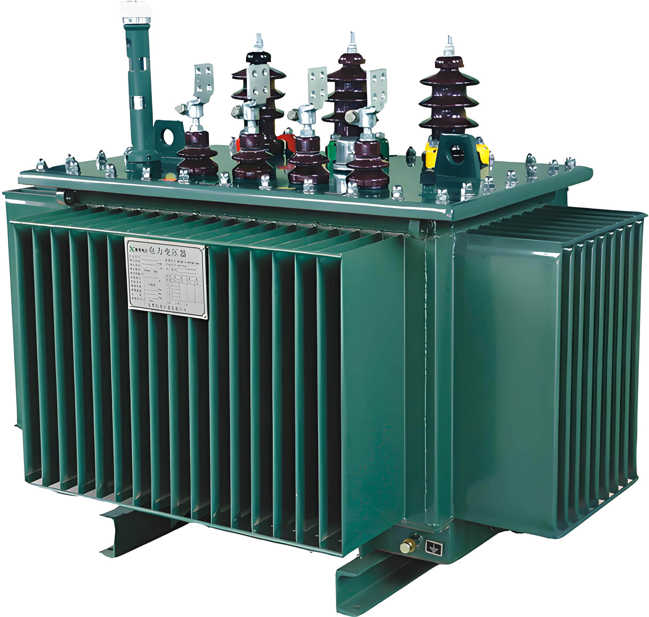
Distribution Transformers Protection
The primary application for drop-out switches is protecting pole-mounted distribution transformers. A typical residential transformer serving 5-10 homes might be rated 25-50 kVA and stepped down from 11 kV to the standard household voltage. The drop-out switch mounted above the transformer provides both isolation for maintenance and overcurrent protection for transformer faults.
This protection is critical because transformers can fail in various ways—winding shorts, insulation breakdown, bushing failures, or even external damage from lightning or animals. When failure occurs, the fault current can be substantial, potentially causing fires or explosions. The drop-out switch fuse quickly isolates the fault, containing the damage and preventing the fault from affecting other customers on the circuit.
Overhead Power Line Systems
Beyond individual transformers, drop-out switches serve as sectionalizing devices in overhead distribution networks. Strategic placement allows utilities to isolate sections of line for maintenance without de-energizing the entire circuit. For example, a long rural distribution feeder might have drop-out switches every few miles, allowing crews to isolate specific sections for tree trimming, conductor replacement, or other work.
This sectionalizing function reduces the number of customers affected by planned outages and helps with fault location. When a fault occurs somewhere on a long circuit, utility operators can methodically open drop-out switches to narrow down the fault location, reducing troubleshooting time and restoration delays.
Rural Electrical Networks
Rural electrification relies heavily on drop-out switches due to their cost-effectiveness and reliability. Rural circuits often extend for miles with relatively few customers per mile, making expensive automated switchgear economically impractical. Drop-out switches provide adequate protection and isolation at a fraction of the cost of enclosed switchgear or circuit breakers.
In developing regions, where electrical infrastructure is still expanding, drop-out switches enable utilities to extend service to remote areas affordably. Their simplicity means less training is required for maintenance personnel, and their robustness means they continue operating reliably even with minimal maintenance—important factors where technical resources may be limited.
Industrial Power Distribution
Industrial facilities with private distribution systems use drop-out switches for isolating equipment and sectionalizing their internal networks. A manufacturing plant might have several buildings fed from a central substation, with drop-out switches providing isolation at building entrances. Mines use them extensively for isolating mobile equipment substations and sectioning their underground or pit distribution systems.
The visible confirmation aspect appeals to industrial safety managers. During lockout/tagout procedures, workers can visually verify that isolation has been achieved before beginning work on equipment. This physical verification adds an extra layer of safety beyond just checking indicator lights or reading instruments.
Temporary Disconnection Scenarios
Construction sites, festivals, agricultural events, and other temporary installations frequently use drop-out switches for connecting and disconnecting temporary loads. A county fair might need several hundred kilowatts for a week—drop-out switches provide a safe, cost-effective connection and disconnection point. Similarly, construction sites for large projects might require temporary distribution transformers that will be removed once the project is complete.
The ease of operation with a hot stick means connections and disconnections can be performed quickly by trained personnel without specialized tools or extended outages. This flexibility makes drop-out switches ideal for applications where equipment is routinely connected and disconnected.

Advantages of Drop-out Isolating Switches
Visual Confirmation of Disconnection
The paramount advantage of drop-out switches is unmistakable visual confirmation of the open position. When a maintenance worker approaches a transformer or other equipment, they can look up and immediately see whether the drop-out switch is open—no ambiguity, no need for voltage testing to confirm the status. This visible air gap, often several inches wide and clearly visible from ground level, provides confidence that the circuit is truly isolated.
This characteristic is especially valuable in situations where multiple circuits are present in close proximity. On a distribution pole carrying several different circuits at various voltage levels, being able to visually confirm which switches are open prevents potentially fatal mistakes. The human eye can quickly scan and verify status, whereas indicator lights or position markers could be confused or misread.
Safety Benefits for Maintenance Personnel
Beyond visual confirmation, drop-out switches enhance safety through their operation from ground level. Workers don't need to climb poles to operate the switches—they can open and close them using insulated hot sticks while remaining safely on the ground. This ground-level operation eliminates fall hazards and reduces exposure to energized conductors.
The positive opening action ensures that once the blade drops, it stays open until deliberately reclosed. There's no possibility of accidental reclosure due to mechanical failure or external forces. The gravity-operated mechanism is fail-safe—it cannot fail in a way that would close the switch unexpectedly.
Cost-Effectiveness Compared to Alternatives
Drop-out switches represent one of the most economical solutions for medium-voltage isolation and protection. A typical 15 kV fused drop-out switch might cost $150-$300, while an equivalent circuit breaker or enclosed load-break switch could cost thousands of dollars. For utilities serving thousands of distribution transformers, this cost difference is substantial.
The economic advantage extends beyond initial purchase price. Installation is straightforward, requiring basic pole-mounting hardware and conductor connections. Maintenance costs remain low due to the simple mechanical design. Over a 30-year service life, the total cost of ownership for drop-out switches is typically far lower than more sophisticated alternatives.
Simple and Reliable Operation
Mechanical simplicity translates to operational reliability. With only a few moving parts and no complex mechanisms, there's little that can go wrong. The gravity-operated opening means no springs to fatigue, no stored-energy mechanisms to fail, no electrical controls to malfunction. This simplicity has been proven through decades of service in all climates and conditions.
Operating procedures are straightforward and easily taught. New utility workers can learn proper operation techniques in a few hours of training. The intuitive design—pull down to open, push up to close—minimizes the chance of operational errors. This ease of use contributes to safe, efficient utility operations.
Easy Fault Detection
When a drop-out switch operates automatically due to a fault, it provides an immediate visible indication of the problem. Utility operators or field crews can quickly identify which transformer or circuit section has experienced a fault by observing which drop-out switches have opened. This visual indication speeds troubleshooting and reduces the time needed to locate problems.
The characteristic "signature" of fuse expulsion—the visible gases expelled from the fuse tube during operation—can sometimes provide clues about the nature of the fault. Experienced utility workers learn to interpret these signs, gaining insights that guide their troubleshooting approach.
Limitations and Challenges
Load-Breaking Capabilities
The primary limitation of drop-out switches is their restricted ability to interrupt load current safely. Standard drop-out switches are designed for isolation, not load breaking. While they can successfully interrupt fault currents when the fuse operates (because the expulsion fuse provides arc-interrupting capability), they should not be manually opened under normal load conditions.
Opening a drop-out switch under load creates an arc between the separating contacts. Without proper arc-interrupting mechanisms, this arc can be sustained, potentially causing severe damage to the switch, creating a safety hazard, or failing to actually interrupt the circuit. Industry standards and utility operating procedures typically prohibit opening drop-out switches under load unless they're specifically rated for load-break operation—a special category with additional arc-interrupting features.
This limitation requires careful operational planning. Before opening a drop-out switch manually, the load must be transferred to another source or customers must be notified of an outage. Load-break switches or circuit breakers must be used if routine load interruption is required.
Weather and Environmental Factors
Despite being designed for outdoor use, drop-out switches face challenges from environmental conditions. Ice accumulation can prevent proper drop-out action by adding weight to the blade assembly or by bridging the contacts when ice forms between them. Ice bridging creates a conductive path that prevents true isolation, negating the protective function of the switch.
Salt contamination in coastal areas or industrial pollution can create tracking paths across the insulating surfaces. These conductive deposits gradually deteriorate insulation performance and can lead to flashovers. Regular washing or cleaning is necessary in heavily contaminated environments, adding to maintenance requirements.
Extreme temperatures affect mechanical operation. Very cold weather can cause lubricants to stiffen, potentially interfering with smooth operation. UV radiation gradually degrades polymer insulators, though modern formulations resist this degradation better than older materials. Wildlife, particularly birds and squirrels, can cause problems by nesting on the switches or chewing on components.
Maintenance Requirements
While drop-out switches require less maintenance than many alternatives, they're not maintenance-free. Regular inspection is necessary to identify worn contacts, degraded insulators, or loose connections. Contact surfaces accumulate oxidation and contamination over time, increasing resistance and causing heating. Periodic cleaning or contact replacement maintains reliable operation.
The operating mechanism requires occasional lubrication to ensure smooth movement. Hinges, latches, and other moving parts can seize from corrosion or accumulation of dirt if neglected. In harsh environments, more frequent maintenance may be necessary to maintain reliable operation.
Fuse links are consumable items that require replacement after each operation. Utilities must maintain adequate fuse link inventories and ensure field crews have the right ratings available for replacement. Incorrectly rated replacement fuses can compromise protection or cause nuisance operations.
Voltage and Current Limitations
Drop-out switches are practical only within certain voltage and current ranges. Above approximately 38-46 kV, the physical size required for adequate insulation becomes unwieldy, and other switchgear types become more practical. The current-carrying capacity is also limited—typical units are rated for 100-200 amperes continuous current, with higher ratings available but becoming physically large and expensive.
The interrupting capability of the fuse limits the fault current that can be safely cleared. While modern expulsion fuses can interrupt substantial fault currents (10,000-20,000 amperes or more), this is still below the interrupting ratings available with circuit breakers. In systems with very high fault levels, drop-out switches may not provide adequate protection.
When They're NOT the Right Choice
Several scenarios call for alternatives to drop-out switches. Applications requiring frequent load switching need load-break switches or circuit breakers that can safely interrupt load current hundreds or thousands of times. Automated distribution systems with remote control capability need motorized switches that can be operated remotely, not manually-operated drop-out switches.
Underground distribution systems typically use enclosed switchgear rather than outdoor drop-out switches. The confined spaces and different physical arrangements underground make drop-out switches impractical. Similarly, substations with high voltage levels (69 kV and above) use different types of switchgear designed for those applications.
Where precise, coordinated protection is required, circuit breakers with electronic relays provide better control than drop-out switches with fuses. Complex industrial systems or critical infrastructure often justify the higher cost of more sophisticated protection and switching equipment.
Installation Guidelines
Site Selection and Positioning
Proper site selection ensures safe, reliable operation throughout the switch's service life. The mounting location must provide adequate clearance from ground, from other conductors, and from structures. Accessibility is crucial—utility workers must be able to reach the switch safely with hot sticks from ground level or from a bucket truck. Obstructions like tree limbs, building overhangs, or other equipment can interfere with operation and should be avoided.
The mounting structure must be sturdy enough to support the mechanical loads imposed by the switch, conductors, and environmental forces. Distribution poles must be properly classified for the expected loads. In high-wind areas or locations subject to ice loading, additional structural consideration may be necessary. The orientation of the switch on the pole should follow utility standards—typically mounted facing the street or access road for easy observation and operation.
Mounting Height Recommendations
Industry standards and utility practices specify minimum mounting heights for drop-out switches, balancing several factors. The switch must be high enough to maintain adequate ground clearance when the blade is in the dropped position, yet low enough that utility workers can comfortably operate it with standard hot sticks (typically 6-12 feet long).
Common mounting heights place the operating ring approximately 15-25 feet above ground level, though this varies based on voltage class and local requirements. Higher voltage switches may need greater mounting heights to maintain clearances. In areas where vehicular traffic passes beneath the switch, additional height may be required to ensure clearance for trucks and equipment.
Clearance Requirements
Electrical clearances are critical for safety and reliable operation. The National Electrical Safety Code (NESC) and international equivalents specify minimum clearances based on voltage class. These clearances must be maintained between energized parts and ground, between phases, and between the switch and other structures or conductors.
Typical clearance requirements for a 15 kV installation might include 8 feet of vertical clearance above ground, 3-4 feet between phases, and similar distances to buildings or other grounded structures. These clearances increase with voltage—a 38 kV installation requires significantly more space. During installation, all clearances must be verified and documented to ensure code compliance.
Proper Grounding Procedures
Grounding connects the switch frame and mounting hardware to earth potential, protecting against lightning strikes and providing a safe path for fault currents. The grounding conductor, typically copper or aluminum, runs down the pole to a ground rod or grounding grid. The conductor size must be adequate for the expected fault current levels.
All metallic parts that could become energized during a fault must be grounded. This includes the switch body, mounting bracket, and associated hardware. Connections must be mechanically secure and electrically sound, using appropriate connectors or clamps. Regular inspection ensures ground connections remain intact despite vibration, thermal cycling, and corrosion.
Environmental Considerations
Installation practices must account for the specific environmental conditions at each location. In coastal areas with salt spray, the selection of corrosion-resistant materials and the application of protective coatings extend service life. In areas with heavy ice loading, consideration of the weight that accumulated ice adds to the blade assembly ensures reliable drop-out action.
Industrial areas with heavy pollution may require switches with greater creepage distances or more frequent cleaning schedules. Desert installations face challenges from sand, dust, and UV exposure.