1. Unpacking the Core Classifications
1.1. The Two Major Transformer Classifications
The electrical transformer is an indispensable component in modern power delivery systems, and its classification is fundamentally split into two primary methodologies essential for engineering comprehension. This dual system is vitally important because it addresses distinct operational and design imperatives.
The first approach involves the Classification by Power Supply, which cleanly separates all units into Single-Phase Transformers and Three-Phase Transformers. This division is based purely on the electrical supply configuration.
The second and equally critical method categorizes them by their specific role and scale within the electrical grid, formally known as the Classification by Application or Function. This essentially divides them into Power Transformers for bulk high-voltage transmission and Distribution Transformers for final utility service step-down.
The transformer’s core mission remains consistent: to efficiently convert AC voltage and current while ideally conserving power. However, the specific operating environment and economic constraints rigorously dictate the necessary structural priorities.
1.2. The Core Principle and Engineering Context
The operational bedrock of every single transformer relies entirely on the immutable physical law discovered by Michael Faraday, formally termed Faraday's Law of Induction. The alternating current flowing through the primary winding generates a corresponding alternating magnetic flux within the core.
This induced magnetic flux then magnetically couples with the secondary winding, leading to the generation of an electromotive force (EMF) and thereby enabling the seamless transfer of electrical energy across the coils. The crucial determination of the voltage conversion ratio is based strictly on the proportional relationship between the number of turns in the primary and secondary coils, which is known simply as the Turns Ratio.
In practical engineering terms, transformers are essential for shaping the entire electrical infrastructure, starting by taking the high-voltage energy produced at a generating station and immediately boosting it further for ultra-high-voltage (UHV) long-distance transmission. This process is necessary to effectively minimize resistive ohmic losses over vast distances.
They then manage the systematic, step-by-step reduction of this voltage through various substations until it finally reaches the safe low voltage levels required by end-users. This sophisticated process guarantees that the entire grid operates with maximum efficiency and unquestionable safety standards.
1.3. The Engineering Logic Behind the Classification
The persistent necessity for these two distinct, yet sometimes overlapping, classification systems within the engineering domain stems from the fact that each addresses a unique set of design criteria and application constraints.
Classification by Power Supply is fundamentally concerned with matching the transformer's electrical structure to the precise characteristics of the load and the feeding circuit. For example, three-phase units are the non-negotiable choice for handling balanced three-phase systems, which are mandatory for massive power transmission and driving heavy-duty induction motors.
Single-phase units, conversely, are designed to serve simpler, more geographically dispersed, and generally lower-power commercial and residential needs.
Meanwhile, the Classification by Application or Function is primarily used to optimize the transformer’s economic viability, running performance metrics, and specific design focus. High-capacity Power Transformers, which operate at the critical transmission stage, are exclusively engineered for peak efficiency and absolute reliability under continuous load.
In sharp contrast, lower-capacity Distribution Transformers must be designed to rigorously balance initial investment cost against continuous energy losses while operating in environments characterized by wildly fluctuating and diverse loads.
Note: The number of phases dictates the circuitry that the transformer connects to and handles. The application function dictates the transformer's structural design standards and the core economic priorities that drive its production.
2. Part One: Classification by Power Supply
The most rudimentary separation within the electrical power system hinges on the number of alternating current phases being actively utilized. This parameter fundamentally dictates the stability, efficiency, and precise mechanism of power transmission and equipment drive.

2.1. Single-Phase Transformers
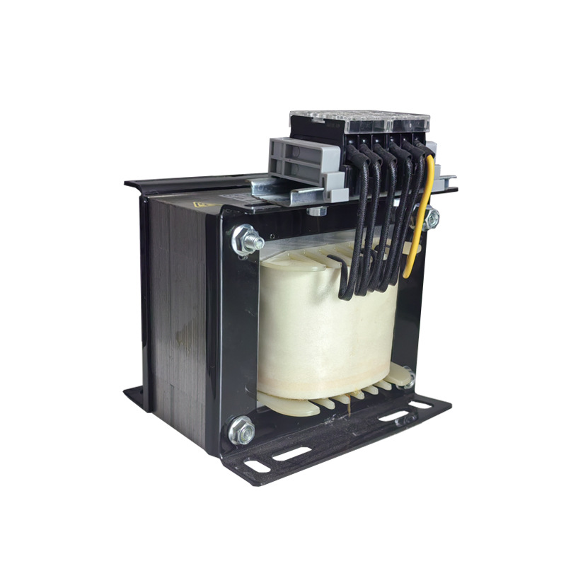
A Single-Phase Transformer is defined by its simple design, typically incorporating only one primary winding and a corresponding single secondary winding set. These units are specifically engineered for exclusive use in single-phase AC circuits.
The result is that their power output is inherently non-constant over a given cycle, which inevitably leads to instantaneous power fluctuations.
∙ Principle and Application: These units constitute the primary power source for residential complexes, smaller commercial facilities, and dedicated lighting systems due to their straightforward operation. The principal advantages of single-phase units include their relative ease of installation, simplified wiring requirements, and their generally lower overall component cost. This profile positions them as the default solution for low-power and end-of-line distribution requirements.

2.2. Three-Phase Transformers
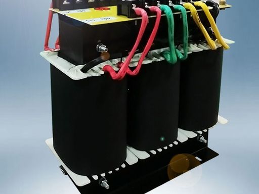
The Three-Phase Transformer stands as the undisputed workhorse of the power system, actively serving large-scale industrial consumers, major commercial operations, and the entire power transmission network. It consistently offers superior power capacity and inherent operational stability under heavy load.
Composed of three distinct sets of windings, this system ensures that the three individual voltage waveforms are separated by precisely 120∘ electrical degrees.
The sum of the instantaneous power across all three phases is theoretically constant under ideal conditions, which in turn delivers an exceptionally smooth and continuous power output. This smooth output is an absolute necessity for successfully driving heavy inductive loads such as large induction motors with minimal vibration or stress.
∙ Engineering Detail: Winding Connection Types
One of the most critical engineering choices for a three-phase transformer revolves around the type of winding connection implemented, most notably the Wye (Y) and Delta () configurations. The Y-Connection offers the essential feature of providing a permanent neutral point, which allows the system to supply both phase and line voltages while inherently enhancing insulation security and grounding possibilities.
Conversely, the Connection offers a crucial technical advantage by creating an internal, closed circulation path for any undesirable third harmonic currents that are inherently present in the system.
This internal circulation path is key because it effectively prevents the third harmonic component from escaping into the main power grid. It thereby plays a critical role in maintaining the overall quality and integrity of the grid's voltage waveform.
The specific Connection Group designation (e.g., Dy11) meticulously defines the exact phase relationship between the primary and secondary voltages, which is a vital parameter for grid synchronization and successful parallel operation of multiple transformers across different substations.

Tip: The Δ connection within a three-phase transformer is a powerful engineering tool for suppressing third-harmonic distortions in the power system. The Y connection provides the necessary neutral point, serving as the basis for three-phase, four-wire distribution.
3. Part Two: Classification by Application/Function
The exact physical location of a transformer within the larger electrical system and the specific operational tasks it is assigned fundamentally dictate vast disparities in its design, manufacturing standards, and required operational criteria. These inherent differences underscore precisely why a single design cannot universally meet the stringent and varied demands of the entire grid architecture.
3.1. Power Transformers
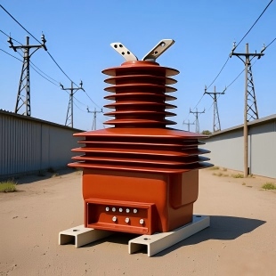
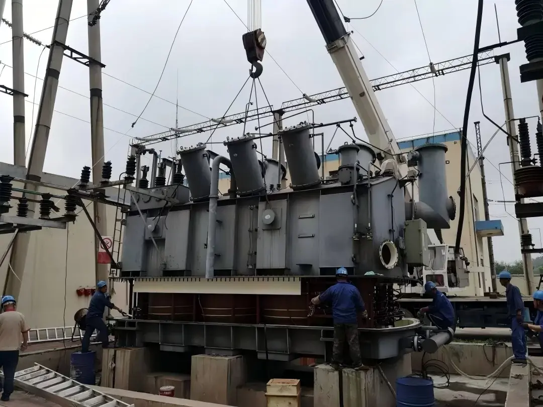
Power Transformers are primarily deployed within the transmission sector of the grid, where their singular objective is the highly efficient and utterly reliable transfer of electrical energy at immense scale and very high voltages. These gargantuan units are typically situated at the power generation plants themselves, where they initially step up the voltage for transmission, or at major transmission substations, where they manage significant bulk power voltage conversions between grid regions.
They are rightly considered the absolute backbone of the electrical grid due to their massive physical size and exceptionally high ratings, generally exceeding. They are meticulously designed for absolute peak operational efficiency, often achieving verifiable efficiencies above 99%.
∙ Design and Operational Priorities
Insulation and Mechanical Strength: Operating in Extra-High Voltage (EHV) environments necessitates extremely robust and highly sophisticated insulation design to prevent catastrophic flashover failures. Furthermore, they must possess extraordinary mechanical resilience to withstand the severe electrodynamic stresses generated instantaneously during fault conditions, such as short circuits, which could otherwise lead to immediate structural collapse.
On-Load Tap Changer (OLTC): Almost all Power Transformers are equipped with an On-Load Tap Changer. This crucial, complex feature enables operators to adjust the turns ratio in real-time without ever disrupting the load, which is essential for maintaining consistent and stable voltage levels across the vast, interconnected transmission network.
3.2. Distribution Transformers
Distribution Transformers serve as the crucial nervous system of the electrical grid, representing the final stage of the utility network where medium-level voltages are stepped down to the lower voltages that are safe and readily usable for end-consumers. They are by far the most numerous transformer type, ubiquitously scattered across residential zones, industrial parks, and commercial districts. These smaller units are uniformly characterized by a lower power rating, typically below.
∙ Design and Economic Priorities
Loss Characteristics: The loading on a Distribution Transformer fluctuates wildly and is often quite low for significant periods, making the pursuit of maximum full-load efficiency impractical and economically unsound. The design focus must instead shift decisively to the Average Efficiency calculated over a 24-hour cycle.
This shift involves a particular emphasis on minimizing the No-Load Loss (determined by core loss), since this energy loss is continuous and unavoidable as long as the unit is energized and connected to the source. Modern utility standards, therefore, mandate the use of technologies like amorphous metal cores to drastically reduce this constant energy bleed.
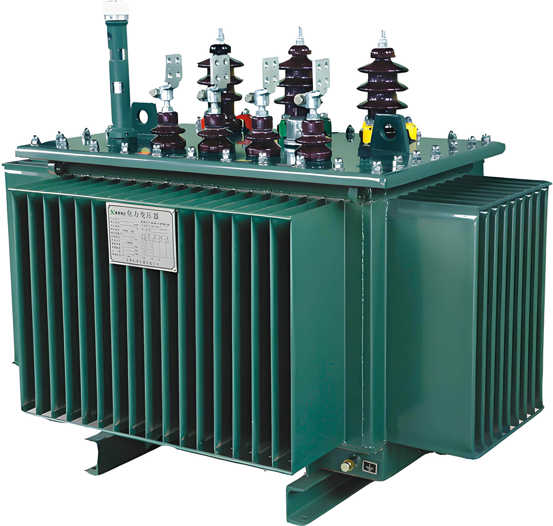
Environmental Adaptability: Distribution units commonly employ both oil-immersed construction (which offers lower cost and superior heat dissipation) and dry-type construction (which is inherently fire-resistant, explosion-proof, and environmentally friendly) to perfectly suit the diverse installation requirements of various environments. The choice between the two is a critical factor influencing both safety and cost in urban planning.

Note: The fundamental design priority for a Power Transformer is maximizing reliability and extreme full-load efficiency. The focus for a Distribution Transformer is managing cost, minimizing losses (especially the continuous no-load loss), and ensuring adaptability to diverse environmental conditions.
【Essential Video Supplement: Power vs. Distribution Transformer Differences】
This video, presented by a professional electrical engineer, offers a systematic and comprehensive comparison between the Power Transformer and the Distribution Transformer based on their application, power rating, typical load factor, and, most importantly, their respective loss management strategies.
Watching this will provide a vital, intuitive grasp of the engineering design compromises and the resulting economic decisions discussed in the following technical section.
Power & Distribution Transformer | What are the differences | TheElectricalGuy
(This content directly supports the advanced discussions on operating conditions, efficiency goals, and loss design.)
4. Part Three: The Four Transformer Types and the Engineer's Decision Logic
By thoroughly analyzing these contrasting attributes, electrical professionals can gain a crystal-clear understanding of the specific roles each type of transformer is meant to fulfill within a functional engineering framework. The following table provides a quick reference for the major distinguishing features across the four types.
4.1. Key Characteristics Comparison Table

4.2. The Engineer's Decision Matrix: Selecting the Right Transformer
For a skilled electrical engineer, selecting the appropriate transformer is far more than a simple parameter matching exercise; it represents a complex, integrated decision-making process. This process must meticulously weigh stringent technical requirements, economic feasibility, and all pertinent environmental constraints.
This systematic approach ensures that the chosen unit is perfectly optimized for its critical long-term function and overall cost effectiveness.
∙ Step 1: Load and Supply Matching (Determining the Phase)
The process begins with a precise Needs Analysis to establish whether the connected loads are predominantly single-phase or three-phase, which dictates the fundamental choice. You must choose a Three-Phase Unit if the system needs to handle complex three-phase or mixed loads.
Alternatively, you would select a simpler Single-Phase Unit if the requirement is strictly limited to small, localized single-phase loads.
∙ Step 2: Capacity and Location Assessment (Determining the Functional Type)
The next crucial step involves an accurate Capacity and Location Judgment to determine the unit's functional category. If the required capacity is large and the unit is positioned on a primary transmission route, a Power Transformer is the necessary and non-negotiable choice.
However, if the capacity is lower and the unit is located near the final consumer, a Distribution Transformer is the specified standard. This step establishes the first critical benchmark for applying the correct design standards and operational expectations.
∙ Step 3: Environment and Safety Considerations (Determining the Structure)
Engineers must then conduct a thorough Installation Environment and Safety Assessment to definitively decide on the physical structure. In indoor settings, high-rise buildings, or any area with stringent fire safety requirements, the fire-proof Dry-Type Transformer must be prioritized and often legally mandated.
Outdoor installations or locations with adequate fire isolation provisions can utilize the more economical and efficient Oil-Immersed Transformer.
∙ Step 4: Efficiency and Economic Trade-offs (Determining Technical Specifications)
The final stage involves a meticulous Efficiency and Economic Trade-off based on a strict engineering principle. For Distribution Transformers that operate at a low annual average load factor, the priority must be given to models that feature low No-Load Loss (high energy efficiency) to minimize long-term operational electricity costs.
In contrast, for Power Transformers that run consistently at high loads, the design must carefully balance both the no-load and the full-load loss profiles to achieve maximum peak efficiency.

Tip: The decision between environment and safety (Dry-Type vs. Oil-Immersed) and the critical balance between economic benefit (high efficiency vs. initial purchase cost) often presents a far greater test of an engineer's experience. This is often more challenging than merely matching basic technical parameters.
5. Conclusion: Summary and Future Trends
5.1. Summary of Key Engineering Points
The electrical transformer is the undisputed foundational cornerstone of the entire power system, and its two fundamental classification methods—Single/Three-Phase and Power/Distribution—define its role based on electrical circuit characteristics and system functionality, respectively. Single-Phase units are tailored to support domestic life and simple commercial activities, while Three-Phase units are essential for driving complex industrial machinery.
Furthermore, Power Transformers guarantee the reliability and peak efficiency of long-distance transmission, while Distribution Transformers are crucial for ensuring safe and stable power delivery to the final point of consumption.
For any competent electrical engineer, a deep and comprehensive understanding of these four primary types and their associated technical differentiations is the absolute prerequisite for correct equipment selection. It is the primary way to ensure safe, economically sound system operation.
5.2. Future Trends in Transformer Technology
Transformer technology is currently on the cusp of two revolutionary waves that promise to fundamentally reshape the power grid infrastructure over the next few decades.
∙ Smart Transformers (STs): These highly advanced units integrate sophisticated sensors, communication modules, and edge computing capabilities, effectively transforming the traditional, passive transformer into an active system component. This active component offers real-time state monitoring, advanced fault diagnostics, remote voltage control, and sophisticated predictive load forecasting.
This technological evolution is absolutely vital for the stable and adaptive operation of complex, highly variable Smart Grids and localized Microgrids, thereby marking the inevitable trend toward the complete digitalization of the power network.
∙ Solid-State Transformers (SSTs): SSTs represent a radical technological shift, utilizing power electronic devices to entirely replace the traditional bulk iron core and copper windings of the conventional utility frequency transformer. SSTs offer revolutionary advantages, including a smaller footprint, significantly lighter weight, the ability to control bidirectional power flow, and superior power quality conditioning.
They are considered the indispensable future technology for emerging DC Distribution Networks, high-speed electric vehicle charging stations, and the highly efficient integration of renewable energy sources into the existing grid.

6. Frequently Asked Questions (FAQ)
∙ Q1: Can a Single-Phase Transformer be connected to a Three-Phase Supply?
Yes, technically it can be connected, but the operational context and long-term consequences are critical to understand. To fulfill the single-phase power needs of residential or small commercial sites, the main service transformer is invariably a three-phase unit.
The single-phase power (220V/120V) is then safely drawn between any one phase line and the neutral line from its Y-connected secondary side.
When connecting, however, strict attention must be paid to balancing the three-phase loads, rigorously ensuring that the single-phase loads on each phase are as evenly distributed as possible to prevent dangerous current imbalance and excessive neutral conductor current. This persistent imbalance would severely degrade the overall quality of the power supply.
∙ Q2: Why do Power Transformers typically utilize On-Load Tap Changers (OLTC), while Distribution Transformers often use Off-Load Tap Changers?
This difference is fundamentally dictated by their respective mission objectives within the larger power system. The Power Transformer is situated on the primary transmission network where voltage fluctuations are complex, frequent, and globally consequential.
The OLTC is therefore essential for real-time adjustments of the output voltage without necessitating a full power interruption, thus maintaining critical grid stability across vast regions.
The Distribution Transformer, operating at the end of the network, is primarily tasked with a fixed voltage step-down. While off-load tap changing requires a brief service outage, it is structurally much simpler and lower in cost, which is sufficient. This simpler approach adequately meets the occasional, seasonal voltage adjustments required at the distribution level, aligning better with the necessary economic constraints of that segment.
∙ Q3: In selecting a transformer structure, what are the main trade-offs between Oil-Immersed and Dry-Type units, particularly concerning fire safety?
The main trade-off points rigorously hinge on cost, cooling performance, and fire safety. Dry-Type Transformers contain no flammable oil, offering superior fire safety, making them mandatory for indoor use in high-rise buildings or densely populated areas with the most stringent fire codes.
Their primary drawback is relatively less efficient heat dissipation and a much higher initial unit cost.
Oil-immersed transformers use specialized insulating oil for cooling, which provides excellent heat transfer and a lower unit cost. They are suitable for outdoor installations or secured areas with adequate fire suppression and isolation measures. The critical decision factor is always the fire and safety code requirements of the specific installation environment.
∙ Q4: How does the Delta (Δ) Winding Connection in a Three-Phase Transformer actually suppress third harmonics?
Third harmonic currents are inherent distortions generated by the non-linear magnetic curve of the transformer's iron core, and critically, they are in-phase across all three phases in a three-phase system.
When the transformer winding utilizes the Delta () connection, this specific configuration forms a closed loop, allowing the third harmonic currents to circulate freely within this internal pathway without ever being released into the external power grid.
This action effectively "traps" the third harmonic, successfully preventing it from negatively affecting the voltage waveform of the external network. This mechanism is why an auxiliary Delta winding is often installed even in Wye-Wye connected transformers.
∙ Q5: When selecting a Distribution Transformer, why is No-Load Loss considered more critical than Full-Load Loss?
This priority is established because Distribution Transformers typically operate at a low annual average load factor, sometimes as low as 30% to 50% in typical residential zones. The No-Load Loss is generated by the excitation current and occurs continuously, 24 hours a day, whenever the transformer is energized.
Conversely, Full-Load Loss (or copper loss) is only generated when load current flows, increasing quadratically with the current. Therefore, at low load factors, the cumulative annual No-Load Loss often significantly outweighs the Load Loss.
Engineers are thus mandated to prioritize models with low No-Load Loss characteristics (high energy efficiency) to maximize the long-term economic benefits over the unit's entire service life.