By: Thor, Electrical Engineer at Weisho Electric Co., Ltd.Thor brings years of experience in substation grounding system design and installation, dedicated to delivering professional and reliable electrical safety solutions.
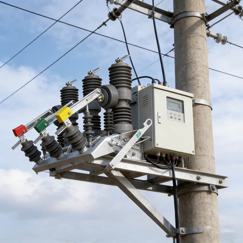
A substation's lightning protection grounding system is vital. It serves as the core safeguard for both the safe operation of electrical equipment and the safety of personnel within the station.
In recent years, there's been a significant shift in the choice of grounding materials for substations worldwide. This isn't just a minor tweak; it's a notable upgrade.
Historically, materials such as galvanized flat steel and copper-clad steel (including continuously cast copper-clad round steel, copper-clad grounding rods, and copper-clad stranded wire) were commonly used. Their primary appeal was their cost-effectiveness.
However, today, pure copper grounding materials are increasingly becoming the preferred choice for large substations, particularly in regions such as Europe and the US. This preference is due to copper's superior conductivity and exceptional corrosion resistance.
Global Trends in Grounding Material Application

Leading power companies across the globe are now actively adopting high-performance copper-based materials. Their goal is clear: to significantly boost the reliability and longevity of their grounding systems.
Let's look at some prime examples of this crucial shift in material application. These cases highlight how top utilities are prioritizing long-term performance.
Pacific Gas and Electric Company (PG&E), USA: In California, PG&E chose 60×6mm pure copper busbars for their 500kV substations' main grounding grids. This decision was driven by the region's need to handle high fault currents and combat the highly corrosive coastal environment. This material choice ensures the grounding grid will last for over 30 years.
National Grid, UK: Key substations within London's grid utilize 250mm² tinned copper-stranded wire. The tinning process is particularly effective, enhancing corrosion resistance in the UK's often damp climate. Copper's high conductivity, meanwhile, allows for the rapid and efficient dissipation of fault currents, which is critical for safety.
Enel, Italy: For substations connecting solar power plants in Sicily, Enel implemented a smart, hybrid solution. They combined 40×4mm pure copper busbars with 185mm² copper-clad steel stranded wire. This mixed design is clever: it guarantees the high conductivity of pure copper while simultaneously reducing overall costs for these large-scale projects by incorporating copper-clad steel.
Step-by-Step Installation Process and Key Considerations
Step One: Substation Grounding Grid Excavation: Depth, Width, and International Standards

Within a substation, certain areas, like fire water pools and the main control building, require deep excavations for their foundations. This means horizontal and vertical grounding electrodes need to be pre-installed directly beneath them.
Construction Standards: The exact depth and width of these grounding trenches are not arbitrary; they must strictly adhere to local and international standards. For example, in the US, compliance with IEEE Std 80, "IEEE Guide for Safety in AC Substation Grounding," is mandatory.
In Europe, EN 50522, "Earthing of power installations exceeding 1 kV a.c.," serves as the primary reference. In Germany, high-voltage substation trenches are typically dug to a depth of 0.8-1.2 meters. This depth is crucial to bypass the frost line and ensure stable, consistent contact with the surrounding soil.
Key Considerations:
Before you start any digging, conduct a thorough underground utility scan of the entire work area. This is non-negotiable; it prevents accidental and costly damage to existing infrastructure like underground cables and pipes.
If you're working in rocky terrain, specialized drilling equipment is essential to assist the excavation process. Importantly, drill holes must be at least 50mm larger than the grounding electrode's diameter. This ensures that the subsequent installation of the grounding electrode and backfilling go smoothly.
Proper soil management during excavation is also crucial. Always stockpile the excavated soil at least 1.5 meters away from the trench edge. This simple precaution helps prevent the soil from collapsing back into the trench, ensuring worker safety and maintaining trench integrity.
Step Two: Main Grounding Grid Material Laying: Vertical Electrodes and Horizontal Conductors

Once the trenches are ready, the next step involves carefully installing the vertical grounding electrodes and horizontal grounding conductors. This is done precisely according to the detailed lightning protection grounding design drawings.
Vertical Grounding Electrodes: The required number of pure copper rods or pipes (for example, 25mm diameter pure copper rods) are driven into the earth. In regions known for high soil resistivity, such as the southwestern deserts of the US, copper-clad electrolytic ion grounding electrodes are frequently employed. These specialized electrodes are designed to significantly enhance overall conductivity in challenging soil conditions.
Horizontal Grounding Conductors: These are laid out horizontally. Common materials include pure copper busbars or tinned copper stranded wire (for instance, 30×3mm pure copper busbars). It's also vital to pre-install grounding lead lines at key connection points for equipment, transformers, and fences. These connections must strictly comply with the requirements outlined in ANSI/IEEE C2, the "National Electrical Safety Code (NESC)."
Key Considerations:
Before driving in any vertical grounding electrodes, always inspect their surfaces for any damage. It's critical to ensure there is no bending, deformation, or other imperfections that could compromise their performance.
When driving them in, use specialized machinery and carefully control both the driving force and the verticality of the electrode. The verticality deviation should never exceed 1% for optimal grounding performance.
When laying horizontal grounding conductors, make sure they lie perfectly flat and straight within the trench. Avoid any twists or kinks in the material. They must also be in tight, continuous contact with the bottom soil, never suspended in the air.
The exact position and quantity of grounding lead lines must strictly follow the design specifications. Make sure to clearly mark the connection points between the lead lines and horizontal conductors. This makes subsequent welding work much easier and more organized.
Step Three: Pure Copper Grounding Material Welding: Exothermic Welding and Quality Control

When connecting pure copper materials, exothermic welding (often called thermite welding) is the preferred method. This technique is widely accepted and recognized within international standards due to its reliability and strong, durable connections.
Mold Selection: You'll need to use specific molds designed for different joint types. These include straight (one-word), T-shaped, and cross-shaped configurations. Crucially, all molds must comply with ASTM B847, "Standard Specification for Exothermic Welding Connection for Electrical Connections," ensuring they meet industry performance and safety criteria.
Flux Selection: The welding powder, or flux, must conform to IEC 61230, "Live working - Portable equipment for earthing or earthing and short-circuiting." For example, a 10mm diameter copper rod joint typically requires 50g of welding powder, while a 30×3mm copper busbar cross joint will need 100g. Using the correct amount is vital for a strong weld.
Quality Control: Every single weld joint must be full, robust, and free of cold welds or imperfections. After welding, a thorough visual inspection is necessary to ensure uniform melt penetration. Additionally, a resistance test must be performed, with each joint resistance measuring ≤50μΩ. These quality checks must comply with CSA C22.2 No.100, "Motors and Generators," standards, emphasizing safety and performance.
Key Considerations:
Before any welding begins, meticulously clean both the mold and the grounding electrode surfaces. This means thoroughly removing any oil, oxide layers, or other impurities. This step is critical for achieving a high-quality, reliable weld.
It's imperative that all operators involved in the welding process are professionally trained. They must strictly follow the instructions provided with the welding powder and precisely control both the welding time and temperature. These parameters are key to a successful exothermic weld.
During the welding process, implementing robust fire prevention measures is non-negotiable. Always have fire extinguishers readily available on-site. This is crucial to prevent any sparks or molten metal from igniting a fire. Safety first!
After welding, allow the weld joint to cool naturally to ambient temperature. This natural cooling is important for the structural integrity of the joint. Never, under any circumstances, use water to cool the joint prematurely, as this can weaken the weld.
Step Four: Grounding Trench Backfilling: Material Selection and Compaction Requirements

Once the welding is completed, the trenches can only be backfilled after receiving approval from a certified supervisor. This supervisor must be qualified, often complying with standards like US OSHA 1910.269 or the EU 2010/35/EU Electrical Work Directive.
Backfill Material: You should primarily use the original excavated soil, ensuring it's free of rocks or debris. However, in areas where soil conductivity is naturally low, specialized conductive backfill soil (such as bentonite-based mixtures) might be necessary. As recommended by IEEE Std 81, "IEEE Guide for Measuring Earth Resistivity, Ground Impedance, and Earth Surface Potentials of a Ground System," backfill should be done in layers. Each layer (typically 150-200mm) should be thoroughly compacted to prevent any air gaps from forming, which could impede conductivity.
Key Considerations:
Before you start backfilling, perform a final check. Confirm that all grounding conductors are properly connected and that their positions precisely meet the design requirements.
The backfill soil needs to have appropriate moisture content for effective compaction. A good rule of thumb is that it should be moist enough to form a ball when squeezed in your hand, but then crumble easily when dropped. This ensures optimal density.
For areas where conductive backfill soil is used, carefully control the mixing ratio with the original soil. Also, pay close attention to the compaction density, following the product's specific instructions.
During the backfilling process, it's crucial to avoid any mechanical compaction over the grounding grid area. Using heavy machinery directly over the grid could cause deformation or even breakage of the grounding conductors, compromising the entire system.
Step Five: Grounding Grid Resistance Measurement: Four-Point Method, Acceptance Criteria, and Data Recording

After the entire installation is complete, the grounding resistance must be precisely measured. This measurement should be performed under specific weather conditions: the soil must be dry, and there should have been no precipitation within the past 72 hours.
Measurement Method: The measurement should utilize the four-point method (Wenner method). This specific technique is outlined in IEC 60479-1, "Effects of current on human beings and livestock - Part 1: General aspects," ensuring a standardized and accurate approach.
Acceptance Criteria: The measured resistance value must strictly meet the project's specific requirements. For example, high-voltage substations (220kV and above) in the EU typically require a resistance of ≤1Ω. In contrast, US distribution substations generally require ≤5Ω, specifically complying with Table 110-1 of the "National Electrical Safety Code (NESC)."
Recording Requirements: All measurement data must be meticulously recorded. This includes timestamps, prevailing weather conditions during the measurement, and vital instrument calibration information (for instance, if a Megger DET4TCR earth resistance tester was used). These records are essential for compliance with ISO 9001 quality management system standards.
Key Considerations:
All measurement instruments used must be calibrated and currently valid within their certification period. Using uncalibrated equipment can lead to inaccurate readings.
During measurement, the placement of the electrodes must strictly conform to specifications. Avoid placing electrodes too close to any other existing grounding electrodes or underground metal facilities. Proximity can significantly interfere with the readings and compromise measurement accuracy.
If the initial measurement results don't meet the required standards, it's critical to analyze the underlying cause. Then, implement appropriate corrective actions, which might include adding more grounding electrodes or changing the backfill materials. After any corrections are made, the grounding resistance must be re-measured until satisfactory results are consistently achieved.
FAQ (Frequently Asked Questions)
Q: How do different soil types affect lightning protection grounding grid installation?
A: Soil resistivity varies widely among different soil types, and this directly impacts the performance of your grounding grid. For instance, clay and humus soils generally have lower resistivity, making installation relatively straightforward.
However, sandy, rocky, and saline-alkaline soils present a greater challenge due to their higher resistivity. In these cases, you might need to employ specialized grounding materials, like electrolytic ion grounding electrodes. Alternatively, you may have to increase the number of grounding electrodes or use conductive backfill soil to effectively lower the grounding resistance. It's crucial to conduct soil resistivity tests before construction to inform a tailored installation plan.
Q: What should be done if incomplete weld joints occur during exothermic welding?
A: An incomplete weld joint can be caused by several factors. These include insufficient welding powder, inadequate cleaning of the mold, impurities on the grounding conductor's surface, or improper temperature control during welding.
If you encounter such a situation, the first step is to completely clean off the incomplete weld joint. Then, thoroughly re-clean both the mold and the grounding conductor. Finally, perform the weld again, ensuring you follow the correct welding powder dosage and operating procedures precisely. After re-welding, it's essential to intensify your quality checks on the new weld joints to ensure every single one meets the required standards.
Q: Grounding grid resistance measurement results are highly affected by weather. How should this be addressed?
A: Weather conditions, such as precipitation and temperature changes, can indeed influence soil resistivity. This, in turn, can lead to variations in your grounding resistance measurement results. Therefore, it's critical to conduct measurements under specific weather conditions: the soil should be dry, and there should have been no precipitation within the preceding 72 hours.
If you encounter special weather situations that prevent measurement within the stipulated timeframe, make sure to record the prevailing weather conditions at that moment. Then, re-measure at a more suitable time later and compare the two sets of results for accurate analysis. Additionally, before measuring, you can pre-treat the soil in the measurement area by clearing any surface water or loosening the topsoil. This helps to minimize the influence of weather factors on your readings.
Q: Pure copper grounding materials are more expensive than other grounding materials. Why are they still widely adopted?
A: It's true that pure copper grounding materials have a higher initial cost compared to some alternatives. However, this higher upfront investment is justified by their outstanding conductivity, superior corrosion resistance, and significantly longer service life.
Over the long term, pure copper grounding grids result in much lower maintenance costs. More importantly, they provide a far more reliable safeguard for substation operations. This reduces the risk of expensive equipment damage and costly power outages that can stem from grounding system failures. When you consider the total life cycle cost, pure copper grounding materials actually offer excellent value, making them the preferred choice for substation projects where safety and reliability are paramount.
Conclusion
A meticulously designed and installed substation lightning protection grounding grid is critical. It's the cornerstone for ensuring the safe and stable operation of any power system.
This article has provided a detailed look at internationally advanced installation procedures and highlighted key considerations for each step. We've also emphasized the global trend towards pure copper grounding materials, outlining their significant advantages in terms of reliability and long-term cost-effectiveness.
By diligently adhering to these international standards and best practices, you can ensure the optimal performance and enduring durability of your grounding system. This commitment to quality will ultimately provide a robust and lasting safety shield for your substation.
Author Information
Author: Thor
Company: Weisho Electric Co., Ltd.
Position: Electrical Engineer
Phone: +86-0577-62788197
WhatsApp: +86 159 5777 0984
Email: [email protected]
Website:
If you have any questions about substation lightning protection grounding systems, or if you have specific project requirements, don't hesitate to reach out to Thor. You can also visit the Weisho Electric Co., Ltd. website. We're here to provide professional, tailored solutions.
References: International power industry practices and technical literature,