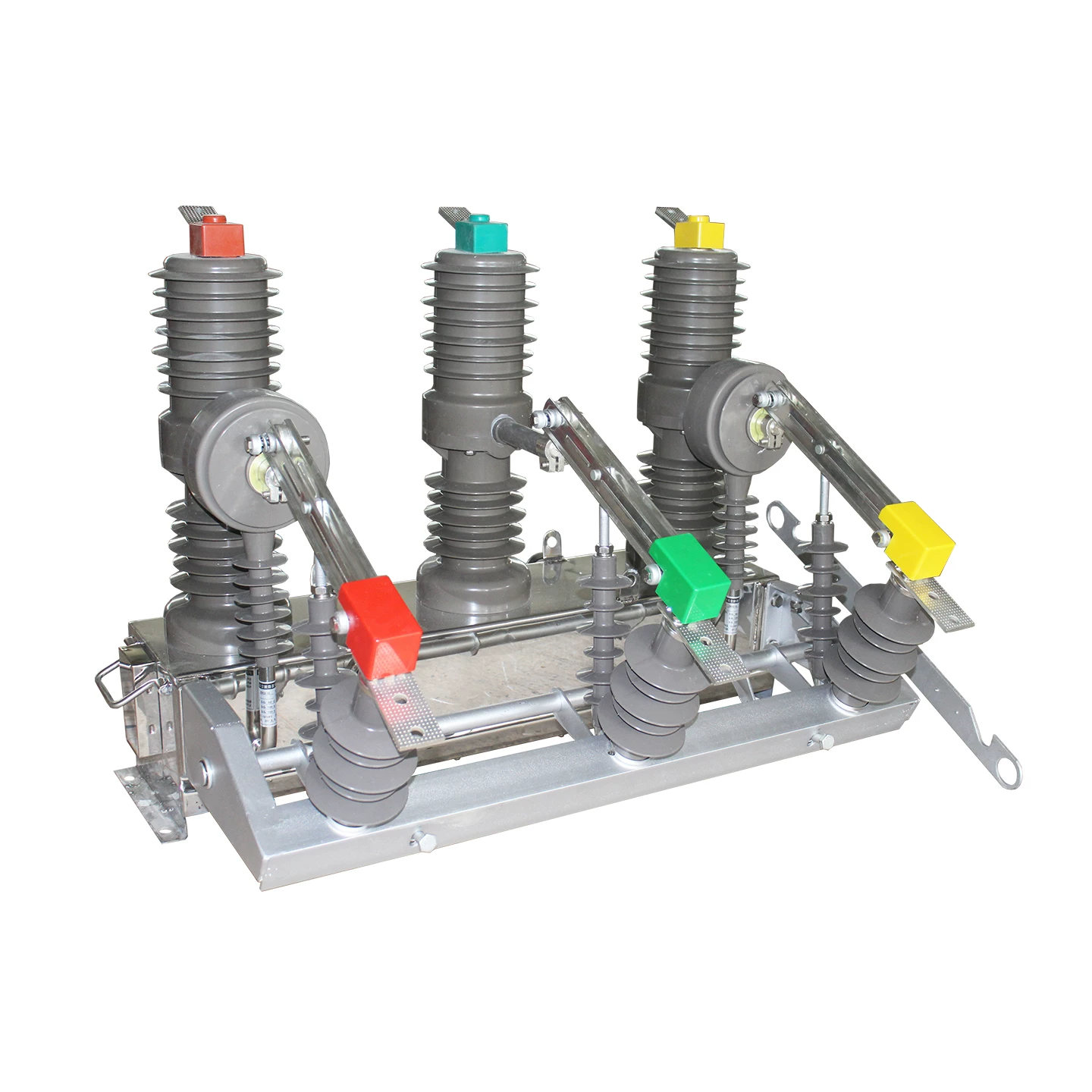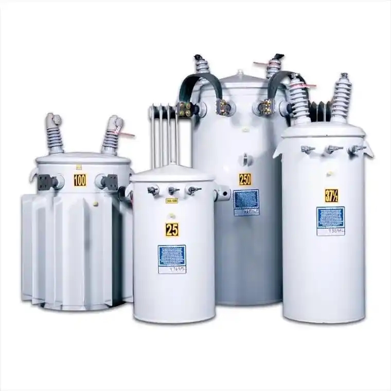
A single-phase transformer is one of the most widely used electrical devices in modern AC systems. It transfers electrical energy from one circuit to another through electromagnetic induction, while changing voltage and current levels without changing frequency.
In practical power networks, this device is everywhere. It supports homes, shops, clinics, control cabinets, test benches, lighting circuits, solar interfaces, and rural distribution lines.
If you have ever seen utility voltage reduced for a house, a control panel stepping 415V or 230V down to 24V, or sensitive equipment isolated from the mains, you have seen the direct value of a single phase transformer in action.
This guide goes deep into the single phase transformer working principle, single phase transformer construction and types, single phase transformer efficiency and losses, single phase transformer applications in power systems, and the single phase transformer equivalent circuit and phasor diagram.
It is written for engineers, buyers, technicians, maintenance teams, project managers, and serious learners who want more than textbook definitions. It focuses on field reality, selection logic, and performance behavior that matter in actual installations.
What Is a Single Phase Transformer?
A single phase transformer is a static electrical machine designed to transfer AC power between two circuits operating on a single phase supply. It works by linking the circuits magnetically through a shared core, rather than electrically through direct conduction.
Its primary job is straightforward: raise voltage, lower voltage, or isolate circuits. In doing so, it helps match the source supply to the load requirement.
Common examples include:
230V to 12V transformers for control and lighting systems
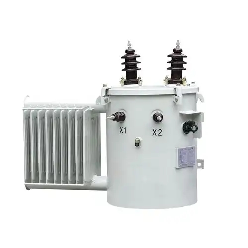
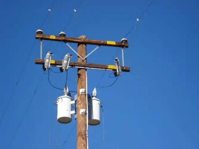
11kV/230V pole-mounted distribution transformers for remote homes
230V/230V isolation transformers for medical, lab, and instrumentation use
480V to 120V control transformers in industrial panels
At the utility level, transformers are essential for efficient power transfer. At the facility level, they support operational safety, voltage matching, and equipment reliability.
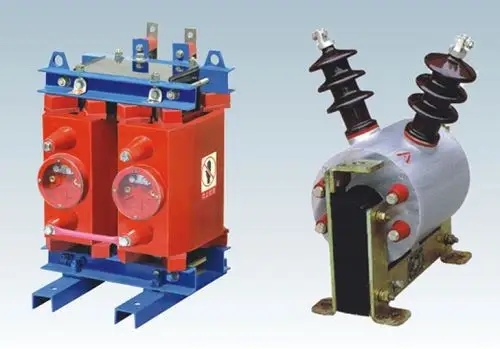
Why Understanding Single Phase Transformers Matters
Many transformer problems do not begin with manufacturing defects. They begin with wrong assumptions.
A transformer that looks adequate on paper may fail early if load type, inrush current, ambient temperature, harmonic content, or duty cycle are ignored. In the field, this leads to overheating, low secondary voltage, nuisance trips, insulation stress, and short service life.
Here are the most common consequences of poor transformer understanding:
Wrong sizing causes overheating and poor voltage regulation
Incorrect voltage ratio leads to under-voltage or over-voltage at the load
Ignoring frequency can increase core losses and saturation risk
Poor installation location raises moisture, dust, and temperature stress
Underestimating inrush and motor/control loads causes fuse blowing and unreliable operation
In a real facility, a transformer is rarely an isolated component. It interacts with circuit breakers, relays, VFDs, UPS systems, solar inverters, grounding systems, and cable runs.
That is why professionals evaluate transformers not only by kVA rating, but also by system behavior under normal load, overload, transient events, and environmental stress.
Manufacturers with strong application support matter here. Companies such as Weisho Electric are often evaluated not only on product specifications, but also on consistency, insulation quality, testing discipline, and the ability to recommend the correct transformer for the actual duty.
How a Single Phase Transformer Works
The single phase transformer working principle is based on Faraday’s law of electromagnetic induction. When alternating current flows through the primary winding, it produces a changing magnetic flux in the core. That changing flux links the secondary winding and induces an electromotive force.
No mechanical motion is required. Energy transfer occurs through the magnetic field.
In simplified form:
AC voltage is applied to the primary winding
A magnetizing current flows and creates alternating flux in the core
The flux links both primary and secondary windings
An induced voltage appears in the secondary winding
When a load is connected, current flows in the secondary circuit
Ideally, input power equals output power. In reality, some power is lost as heat and magnetic loss.
Primary and Secondary Windings
The primary winding is connected to the input AC supply. The secondary winding is connected to the load.
The number of turns on each winding determines the voltage transformation ratio. If the secondary has more turns than the primary, the transformer steps voltage up. If it has fewer turns, it steps voltage down.
Current behaves inversely to voltage in an ideal transformer. This is why a step-down transformer reduces voltage but increases available current on the secondary side.
The basic turns relation is:
V1 / V2 = N1 / N2
Where:
V1 = primary voltage
V2 = secondary voltage
N1 = primary turns
N2 = secondary turns
Mutual Induction and Magnetic Flux
Mutual induction is the core operating mechanism. The alternating current in the primary winding creates a time-varying magnetic flux in the laminated steel core.
Because the core provides a low-reluctance path, most of this flux links both windings. That shared flux induces EMF in each winding in proportion to the number of turns.
The induced EMF equation for sinusoidal operation is commonly written as:
E = 4.44 f N Φm
Where:
E = RMS induced EMF
f = frequency
N = number of turns
Φm = maximum flux in webers
This formula explains why the same transformer must be used at its designed frequency. Lower frequency with the same applied voltage increases flux density and may push the core toward saturation.
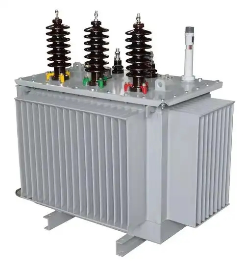
Step-Up vs Step-Down Operation
A step-up transformer increases voltage from primary to secondary. It is used where higher transmission or process voltage is needed.
A step-down transformer decreases voltage from primary to secondary. This is the most common case in residential, commercial, and control applications.
Examples:
230V to 24V control transformer: step-down
120V to 240V specialty supply transformer: step-up
11kV to 230V rural distribution transformer: step-down
In ideal conditions:
I1 / I2 = N2 / N1
So when voltage goes down, current capability goes up accordingly, subject to loss and thermal limits.
Single Phase Transformer Construction and Types
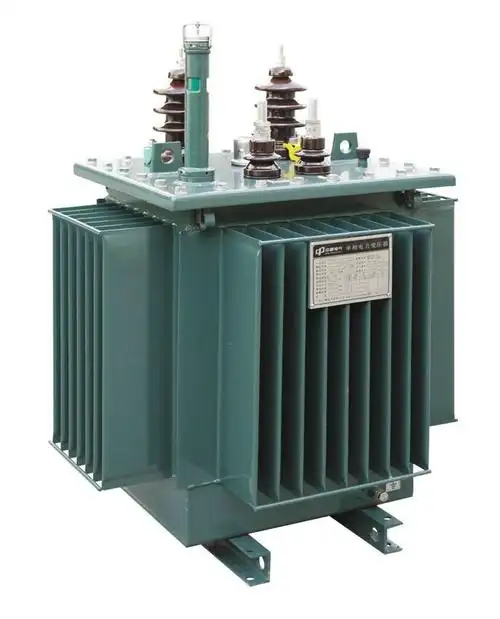
The topic of single phase transformer construction and types is central to design selection. Two transformers with the same kVA may behave differently due to core geometry, winding arrangement, insulation system, cooling design, and intended duty.
The main construction elements directly affect efficiency, short-circuit strength, thermal performance, and service life.
Core, Windings, Insulation, and Tank
The major physical parts of a single phase transformer include the following:
Core: Provides the magnetic path for alternating flux. Usually made of laminated silicon steel to reduce eddy current losses.
Windings: Copper or aluminum conductors wound to create primary and secondary circuits.
Insulation: Separates turns, layers, windings, and core parts to prevent electrical breakdown.
Tank or enclosure: Protects internal parts and may hold insulating oil in oil-filled designs.
Bushings or terminals: Provide safe external electrical connection points.
Cooling path: Air natural, forced air, oil natural, or other methods depending on rating.
In dry-type transformers, heat is removed directly through air circulation and the winding structure. In oil-filled units, the insulating oil assists both cooling and dielectric strength.
Insulation system quality is especially important in industrial, medical, and outdoor applications. Reliable manufacturers, including Weisho Electric, are commonly judged by insulation integrity, thermal class, test records, and consistency under long-term load.
Core-Type vs Shell-Type Transformer
The two classic construction styles are core-type and shell-type.
In a core-type transformer, the windings surround a considerable part of the core. In a shell-type transformer, the core surrounds a greater part of the windings.
Core-type characteristics:
Simpler winding arrangement in many designs
Good cooling accessibility
Often used in power and distribution applications
Can be easier to manufacture in certain rating ranges
Shell-type characteristics:
Better mechanical protection for windings
Reduced leakage flux in many configurations
Often preferred where stronger short-circuit performance is needed
Compact magnetic structure for some special-purpose units
In practice, selection depends on rating, application, cost target, fault level, and design tradition.
Power, Distribution, Isolation, and Instrument Types
Single phase transformers can also be classified by function.
Power transformer: Used where higher power transfer is required, often in generation or transmission-related systems.
Distribution transformer: Supplies end users at utilization voltage, such as homes, farms, and small facilities.
Isolation transformer: Provides galvanic isolation between source and load, often with a 1:1 voltage ratio.
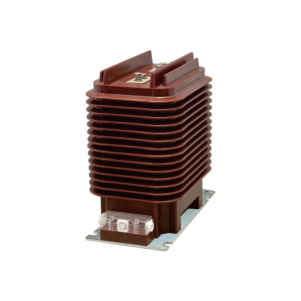
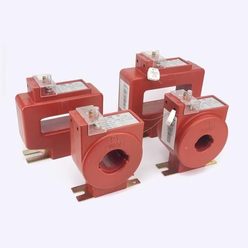
Instrument transformer: Includes potential transformers and current transformers used for measurement and protection.
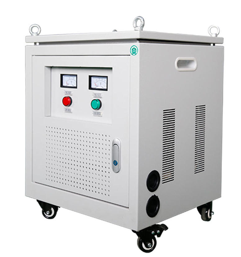
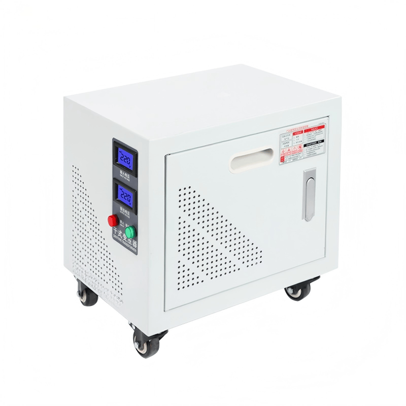
Control transformer: Designed to supply stable low-voltage control circuits, relays, contactors, and automation equipment.
Each type is optimized differently. A control transformer, for example, may be designed to handle high inrush from contactor coils. An isolation transformer prioritizes separation and noise reduction. A distribution transformer emphasizes efficiency at typical daily load cycles.
Single Phase Transformer Equivalent Circuit and Phasor Diagram
The single phase transformer equivalent circuit and phasor diagram are essential tools for analysis, troubleshooting, and performance prediction.
Real transformers are not ideal. Windings have resistance. Flux does not fully link both windings. The core consumes power. These real effects are represented in an equivalent electrical model.
Equivalent Circuit Components
A practical equivalent circuit includes:
Primary winding resistance (R1): Represents copper loss in the primary
Primary leakage reactance (X1): Represents leakage flux not linking the secondary
Secondary winding resistance (R2): Represents copper loss in the secondary
Secondary leakage reactance (X2): Represents secondary leakage flux effect
Core-loss resistance (Rc): Represents hysteresis and eddy current losses
Magnetizing reactance (Xm): Represents current needed to establish mutual flux
The shunt branch formed by Rc and Xm models the no-load behavior. The series branch formed by winding resistance and leakage reactance models load-related voltage drops.
Referred Parameters and Simplified Models
To simplify calculations, engineers often refer all secondary quantities to the primary side, or all primary quantities to the secondary side. This is done using the turns ratio.
If the turns ratio is a = N1/N2, then secondary resistance referred to the primary becomes:
R2' = a²R2
Similarly:
X2' = a²X2
The total equivalent series impedance referred to the primary is then:
Req = R1 + R2'
Xeq = X1 + X2'
This makes voltage drop, efficiency, and fault calculations much easier.
Phasor Diagram Under No-Load and Load Conditions
The phasor diagram shows the angular relationship between voltage, current, flux, and induced EMF.
Under no-load:
The secondary is open
Only a small no-load current flows in the primary
This current has two components: magnetizing current and core-loss current
Flux is nearly in phase with magnetizing current
Primary applied voltage is almost equal and opposite to induced EMF
Under load:
Secondary current flows based on load impedance
The primary draws additional current to balance ampere-turns
Voltage drops appear across series resistance and leakage reactance
The phase angle depends on whether the load is resistive, inductive, or capacitive
This is why lagging power factor loads typically show worse voltage regulation than unity power factor loads.
Single Phase Transformer Efficiency and Losses
The topic of single phase transformer efficiency and losses is where theory meets operating cost. A transformer that runs hot, wastes energy, or drops too much voltage is expensive long after purchase.
Efficiency matters in utilities, factories, commercial buildings, renewable systems, and even laboratory benches where precision and thermal stability are important.
Copper Losses, Core Losses, and Stray Losses
The major loss sources are:
Copper losses: Caused by current flowing through winding resistance. These vary with load current squared.
Core losses: Also called iron losses. These include hysteresis and eddy current losses and remain nearly constant with load at constant voltage and frequency.
Stray losses: Caused by leakage flux inducing currents in structural parts, clamps, tank walls, and nearby conductors.
Hysteresis loss comes from repeated magnetization reversal in the core material. Eddy current loss comes from circulating currents induced in the core, which is why laminations are used.
At low load, core loss is often the dominant factor. At high load, copper loss becomes increasingly important.
Load-Dependent vs Constant Losses
This distinction is practical and important.
Constant losses are mainly core losses. They occur whenever the transformer is energized, even if there is no external load.
Load-dependent losses are mainly copper losses. They increase as current rises.
That is why a lightly loaded transformer may still consume noticeable power over 24 hours. In distribution systems, utilities care greatly about no-load loss because transformers remain energized continuously.
For example, an always-on pole-mounted transformer in a rural area may spend many hours at low load during the day. In such cases, low core loss has direct economic value.
Voltage Regulation and Efficiency Formula
Voltage regulation tells us how much the secondary voltage changes from no-load to full-load, usually expressed as a percentage.
The basic voltage regulation formula is:
Voltage Regulation % = ((Vnl - Vfl) / Vfl) × 100
Where:
Vnl = no-load secondary voltage
Vfl = full-load secondary voltage
The efficiency formula is:
Efficiency % = (Output Power / Input Power) × 100
Or, more practically:
Efficiency % = Output / (Output + Losses) × 100
Maximum efficiency occurs when:
Copper loss = Core loss
This condition matters in transformer design because the expected load profile determines where the manufacturer optimizes efficiency.
Single Phase Transformer Applications in Power Systems
The range of single phase transformer applications in power systems is broader than many buyers first assume. These transformers are not limited to small household products. They are used throughout the electrical chain, from utility service to precision instrumentation.
Residential and Commercial Distribution
In residential areas, single phase transformers step medium distribution voltage down to utilization voltage for houses, apartments, farms, and small shops.
Typical examples include:
11kV to 230V service for homes in many countries
7.2kV to 120/240V service in parts of North America
Lighting and receptacle supply in small commercial buildings
These units must handle daily load variation, seasonal peaks, and long outdoor exposure. Reliability matters because one failed transformer can interrupt service to multiple consumers.
Control Circuits, UPS, and Isolation Use Cases
Control transformers are common in industrial panels. They reduce supply voltage to stable control levels such as 24V, 48V, 110V, or 120V for relays, PLC inputs, contactor coils, alarms, and sensors.
Isolation transformers are used where direct electrical separation is needed. This improves safety, reduces common-mode noise, and protects sensitive loads.
Typical use cases include:
Laboratory benches and test systems
Medical equipment power conditioning
UPS bypass and conditioning sections
Telecom and instrumentation circuits
In these applications, waveform quality, insulation integrity, leakage current limits, and shielding design can matter as much as kVA rating.
Renewable Energy and Rural Power Delivery
Single phase transformers are widely used in renewable systems, especially where the end load is not large enough to justify three-phase infrastructure.
Examples include:
Solar-powered rural pumping systems
Off-grid and hybrid micro-systems
Remote clinics and schools
Battery charging and inverter interface systems
In rural electrification, transformer selection must account for long feeder runs, voltage drop, lightning exposure, and irregular load growth over time.
A well-specified unit from a proven supplier can make a major difference in service continuity. This is one reason project buyers often compare technical support and testing depth when reviewing suppliers such as Weisho Electric.
Single Phase Transformer Ratings and Selection Criteria
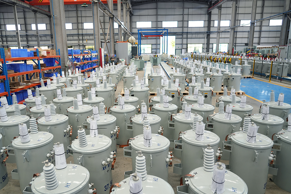
Transformer selection should never be based on voltage alone. The correct unit must fit the electrical duty, thermal environment, mechanical installation, and future operating profile.
kVA Rating, Voltage Ratio, and Frequency
The basic selection inputs are:
kVA rating: Total apparent power required by the load
Primary voltage: Available source voltage
Secondary voltage: Required load voltage
Frequency: Usually 50Hz or 60Hz
A common sizing mistake is to total only steady-state watts while ignoring inrush or starting current. This is a serious issue for magnetic contactors, solenoids, motors, compressors, and some power electronic loads.
For control transformers, inrush VA may be several times the sealed VA. The transformer must support momentary demand without excessive secondary voltage collapse.
Cooling Method and Duty Cycle
The cooling method affects temperature rise and lifespan.
Air-natural dry-type: Common indoors for control, isolation, and small distribution use
Oil-filled: Common outdoors and in distribution duty, especially where cooling and insulation strength are important
Forced cooling: Used in larger or more demanding applications
Duty cycle matters just as much. A transformer serving intermittent loads can sometimes be selected differently than one serving a continuous process line at elevated ambient temperature.
Heat is cumulative. Even a correctly rated transformer can age quickly if ventilation is poor or ambient temperature stays high.
Indoor vs Outdoor Installation Factors
Installation environment changes everything.
For indoor use, consider:
Ventilation
Dust accumulation
Access for inspection
Nearby heat sources
For outdoor use, consider:
Rain and moisture ingress protection
UV resistance
Corrosion protection
Pole or pad mounting arrangement
Surge and lightning exposure
In coastal or chemical environments, enclosure finish and sealing quality become especially important.
Single Phase Transformer Formula Table
| FORMULA NAME | EXPRESSION | PURPOSE |
|---|---|---|
| Turns Ratio | V1 / V2 = N1 / N2 | Relates voltage to winding turns |
| Current Ratio | I1 / I2 = N2 / N1 | Relates current inversely to turns ratio |
| EMF Equation | E = 4.44 f N Φm | Calculates induced RMS EMF |
| Efficiency | Efficiency % = Output / Input × 100 | Measures energy conversion performance |
| Practical Efficiency | Efficiency % = Output / (Output + Losses) × 100 | Includes all losses |
| Voltage Regulation | ((Vnl - Vfl) / Vfl) × 100 | Measures secondary voltage drop from no-load to load |
| Maximum Efficiency Condition | Copper Loss = Core Loss | Identifies optimum operating point |
| Referred Resistance | R2' = a²R2 | Refers secondary resistance to primary side |
| Referred Reactance | X2' = a²X2 | Refers secondary reactance to primary side |
Single Phase Transformer Construction and Types Comparison Table
| TYPE | DESIGN CHARACTERISTIC | MAIN ADVANTAGE | TYPICAL USE |
|---|---|---|---|
| Core-Type | Windings placed around core limbs | Good cooling and common power design | Distribution and general power applications |
| Shell-Type | Core surrounds a larger portion of windings | Better mechanical protection and lower leakage in many designs | Control, electronic, and special-duty transformers |
| Isolation Transformer | Often 1:1 ratio with reinforced insulation | Electrical separation and noise reduction | Medical, laboratory, UPS, instrumentation |
| Distribution Transformer | Optimized for continuous service and low no-load loss | Efficient end-user voltage supply | Homes, shops, rural feeders |
| Instrument Transformer | Designed for measurement/protection accuracy | Safe metering and relay interface | Monitoring and protection circuits |
Single Phase Transformer Losses and Efficiency Table
| LOSS OR PERFORMANCE FACTOR | BEHAVIOR | MAIN CAUSE | PRACTICAL IMPACT |
|---|---|---|---|
| No-Load Loss | Nearly constant | Core hysteresis and eddy currents | Continuous energy use while energized |
| Copper Loss | Varies with load current squared | Winding resistance | Heat rise under load |
| Stray Loss | Increases with leakage flux and load | Induced currents in metallic parts | Additional localized heating |
| Voltage Regulation | Worsens with higher current and low power factor | Series impedance drop | Lower output voltage at load |
| Typical Efficiency Range | About 95% to 99% depending on rating and design | Combined effect of all losses | Operating cost and thermal performance |
Real-World Single Phase Transformer Examples
Real systems are where transformer selection becomes practical instead of theoretical. Below are realistic examples based on common field ratings and operating conditions.
Example: 10 kVA Pole-Mounted Distribution Transformer
Consider a rural distribution transformer rated 10 kVA, 11 kV / 230 V, 50 Hz. This is a realistic size for a small cluster of homes or a remote farm supply point.
The full-load secondary current is approximately:
I = 10,000 / 230 = 43.48 A
If the transformer serves a diversified residential load of 5 kW to 7 kW for most of the day and peaks near 8.5 kW in the evening, it will often operate below full rating. In this pattern, core loss becomes economically important because the unit remains energized 24/7.
Suppose the transformer has:
No-load loss: 45 W
Full-load copper loss: 180 W
Typical full-load efficiency near 97.8% to 98.2%
Daily energy lost to no-load operation alone would be:
0.045 kW × 24 = 1.08 kWh/day
Over one year:
1.08 × 365 = 394.2 kWh
That is why utilities pay close attention to no-load loss standards. Across thousands of installed units, the cost difference becomes substantial.
Field concern in this case:
Long LV line can worsen voltage drop at far-end homes
Lightning surges may stress insulation
Low nighttime load means core loss dominates efficiency economics
Example: 2 kVA Isolation Transformer for Medical or Lab Equipment
Now consider a 2 kVA, 230V/230V isolation transformer used for a laboratory analyzer or medical support device.
Here the key issue is not only voltage conversion. It is galvanic isolation, reduced noise coupling, and user safety.
A typical requirement may include:
Low leakage current
Electrostatic shielding between windings
Tight regulation for sensitive electronics
Quiet acoustic performance in indoor environments
If the connected equipment draws 1.2 kW at 0.9 power factor, the apparent power is about:
S = 1.2 / 0.9 = 1.33 kVA
That gives a practical loading margin below 2 kVA, which is beneficial for thermal headroom and voltage stability.
In hospitals and labs, transformers are often chosen conservatively because transient behavior, leakage control, and insulation reliability matter more than minimum upfront cost.
Example: Control Transformer in Industrial Panels
A common industrial application is a 500 VA or 1 kVA control transformer stepping 415V or 230V down to 110V or 24V for relays, PLCs, and contactor coils.
Suppose a panel uses:
4 contactor coils with high inrush
1 PLC power supply
3 indicator lamps
2 small solenoid valves
The steady-state VA may appear modest. But if multiple coils energize at once, inrush can temporarily be 5 to 10 times the sealed VA for certain electromagnetic loads.
This is why undersized control transformers often cause:
Contactor chatter
PLC resets
Fuse operation on startup
Secondary voltage dip
Experienced panel builders therefore size control transformers using both steady VA and inrush VA, not nameplate watts alone.
Performance Data Table: Typical Single Phase Transformer Values
| RATING | PRIMARY/SECONDARY | TYPICAL NO-LOAD LOSS | TYPICAL FULL-LOAD COPPER LOSS | TYPICAL EFFICIENCY | TYPICAL REGULATION | APPLICATION |
|---|---|---|---|---|---|---|
| 500 VA | 230V / 24V | 8 to 15 W | 18 to 30 W | 90% to 95% | 5% to 10% | Control circuits |
| 2 kVA | 230V / 230V | 20 to 40 W | 45 to 80 W | 95% to 97% | 2% to 5% | Isolation, lab, medical support |
| 5 kVA | 400V / 230V | 30 to 55 W | 90 to 150 W | 96% to 98% | 2% to 4% | Commercial and light industrial use |
| 10 kVA | 11kV / 230V | 40 to 70 W | 150 to 260 W | 97.5% to 98.5% | 2% to 5% | Pole-mounted distribution |
| 25 kVA | 11kV / 230V | 70 to 120 W | 300 to 500 W | 98% to 99% | 2% to 4% | Rural distribution and small commercial service |
These values are representative, not universal. Actual numbers depend on design standard, conductor material, cooling method, efficiency class, and manufacturer practice.
Common Single Phase Transformer Problems and Troubleshooting
Field technicians often see the same failure patterns repeatedly. The visible symptom is usually not the root cause.
Symptoms, Causes, and Corrective Actions
| SYMPTOM | LIKELY CAUSE | CORRECTIVE ACTION |
|---|---|---|
| Overheating | Overload, poor ventilation, harmonic-rich load, high ambient temperature | Measure load current, improve ventilation, resize transformer, verify load profile |
| Excessive humming | Loose core laminations, overvoltage, mechanical vibration, saturation | Check supply voltage and frequency, inspect mounting, tighten structural parts if permitted |
| Low secondary voltage | Undersized transformer, long cable run, high inrush, poor regulation | Check loading, cable drop, inrush demand, and transformer impedance |
| Insulation failure | Moisture ingress, overheating, aging, contamination, surge stress | Insulation resistance test, dry-out or replacement, improve enclosure sealing and surge protection |
| Frequent fuse or breaker trips | Inrush current, shorted turns, downstream fault, wrong protection coordination | Verify inrush characteristics, test winding resistance, inspect downstream circuits, adjust protection selection |
| Burnt smell or discoloration | Thermal overload or insulation breakdown | De-energize immediately and inspect before re-energizing |
One common field mistake is replacing a failed transformer with the same rating without finding the real cause. If the original unit failed because of repeated overload or high inrush, the replacement may fail the same way.
Safety, Testing, and Maintenance Best Practices
Transformer maintenance is not complicated, but it must be disciplined. Small checks done on schedule often prevent expensive failures.
Key best practices include:
Insulation resistance testing to identify moisture, contamination, or aging
Temperature monitoring to catch overload and poor cooling early
Load current measurement to verify actual demand versus nameplate rating
Terminal tightening and visual inspection to prevent hot spots and arcing
Grounding verification for safety and fault performance
Cleaning dry-type units where dust accumulation affects cooling or tracking
For oil-filled distribution transformers, maintenance may also include oil level checks, leak inspection, dielectric testing, and bushing condition assessment.
Safe work rules matter more than speed. Always isolate, lock out, verify absence of voltage, and follow site electrical safety procedures before inspection or testing.
Where reliability is critical, preventive maintenance should be linked to operating data. Temperature rise trend, load history, insulation test trend, and repeated nuisance events together tell a much clearer story than any single test result.
FAQ
What is the working principle of a single phase transformer?
The working principle of a single phase transformer is electromagnetic induction. An AC current in the primary winding creates alternating magnetic flux in the core, and that changing flux induces EMF in the secondary winding.
What are the main types of single phase transformers?
The main types of single phase transformers can be grouped by construction and by application. By construction, the common types are core-type and shell-type. By application, the main categories are power, distribution, isolation, instrument, and control transformers.
What is the difference between a core-type and shell-type transformer?
A core-type transformer has windings arranged around core limbs, while a shell-type transformer has the core surrounding more of the winding structure. Core-type designs often offer simpler cooling access, while shell-type designs can provide better mechanical protection and lower leakage flux in many applications.
How is single phase transformer efficiency calculated?
Single phase transformer efficiency is calculated by dividing output power by input power and multiplying by 100. In practical terms, efficiency can also be written as output power divided by output power plus total losses.
What losses occur in a single phase transformer?
The main losses are copper losses, core losses, hysteresis losses, eddy current losses, and stray losses. Copper losses depend on load current, while core losses remain nearly constant as long as voltage and frequency stay constant.
What is the equivalent circuit of a single phase transformer?
The equivalent circuit of a single phase transformer includes winding resistance, leakage reactance, a magnetizing branch, and a core-loss resistance. These elements model real transformer behavior for calculation of voltage drop, loss, current, and regulation.
Where are single phase transformers used in power systems?
Single phase transformers are used in residential distribution, commercial buildings, industrial control panels, UPS systems, labs, medical installations, renewable energy systems, and rural electrification networks.
How do I choose the right single phase transformer size?
You choose the right size by evaluating load kVA, primary and secondary voltage, frequency, inrush current, duty cycle, cooling method, and installation environment. A correct selection also considers future load growth, voltage regulation needs, and whether the unit will be installed indoors or outdoors.
Conclusion and Key Takeaways
A single phase transformer may appear simple, but correct understanding makes a major difference in safety, efficiency, and long-term reliability.
The most important points are clear:
The single phase transformer working principle is based on electromagnetic induction
The single phase transformer construction and types directly affect cooling, leakage, insulation, and application fit
The single phase transformer equivalent circuit and phasor diagram help predict real operating behavior
The single phase transformer efficiency and losses determine heat rise, operating cost, and service life
The single phase transformer applications in power systems span homes, controls, medical systems, labs, UPS, renewables, and rural distribution
In the real world, the best transformer is not simply the one with the lowest purchase price. It is the one correctly matched to voltage, kVA, frequency, environment, and actual duty cycle.
That is where engineering support matters. A reputable supplier should be able to discuss insulation class, losses, inrush behavior, cooling, regulation, and installation details before you buy.
Get Expert Help Choosing the Right Single Phase Transformer
If you are comparing models, planning a project, replacing a failed unit, or unsure about kVA sizing, now is the time to get expert input.
Contact a transformer specialist today to review your voltage ratio, load profile, installation environment, and performance targets.
Request technical support, compare specification options, and choose a single phase transformer that will perform reliably in the field.
For buyers who need dependable product guidance, tested quality, and application-focused support, reach out to Weisho Electric and discuss the right transformer solution for your system.