No, a voltage transformer (VT) cannot be used as a current transformer (CT). This is true even if their transformation ratios happen to match, but you cannot interchange them in practical applications. Both devices use electromagnetic induction, but they serve different purposes: a voltage transformer (PT) is a precise tool that converts high voltage to low voltage, while a current transformer (CT) helps with safety by changing high current into low current. This article explains the main differences between the two, shares the risks of mixing them up from 12 years of experience, and offers simple ways to tell them apart and choose the right one.
About the Author
Thor
Thor is a skilled electrical engineer with more than 12 years of hands-on experience. His expertise includes operating, maintaining, and fixing high-voltage electrical equipment. He currently works at Weishoelec Co., Ltd. (Weishoelec.com).
Weishoelec is a Chinese manufacturer focused on high-voltage electrical equipment. Our products are used worldwide and have international certifications like IEC and ANSI.
Core Distinctions: The Design and Application Principles of PTs and CTs
High-voltage transformers are designed to manage the unique traits of voltage and current. Voltage stays steady but is high, while current varies a lot and has high peaks. This key difference means that PTs and CTs have opposite structural designs, which is why they cannot be interchanged.
The key difference is in their design goals, from "what they measure" to "how they are built." A PT measures voltage accurately, while a CT monitors high currents safely.
1. Design Objectives: Fundamental Differences from "Measurement Target" to "Structure"
• Voltage Transformer: Like a "Precision Step-Down Power Strip," Designed for High-Voltage Measurement
A PT's main job is to change high grid voltage, like 10kV, to a standard low voltage of 110V or 220V. This is important for instruments and protection devices, helping with tasks like electricity billing or detecting overvoltage conditions. To ensure conversion accuracy (error must be ≤0.5%), its structural design has three key features:
Winding Turns: The primary side has many turns, like a 10kV PT with thousands, which works like a "long wire voltage divider." The secondary side has only a few turns, usually just dozens.
Operating State: Instruments on the secondary side have high impedance, similar to an "unloaded" open-circuit, meaning the core's magnetic field depends only on the primary voltage.
Visible Characteristics: The casing shows "primary voltage / secondary voltage" (e.g., 10kV/100V), and the high-voltage side features clear insulated terminals.
• Current Transformer: Like a "High-Current Converter," Designed for Safety Monitoring
A CT's core task is to convert large line currents (e.g., 1000A) into small currents of 1A/5A. This helps instruments measure better and prevents electric shock or burns from large currents that could occur if connected directly to equipment. To handle surges of 10-30 times the normal value during short circuits, the design has three main features:
Winding Turns: The primary side has few turns, sometimes just 1, acting like a "thick wire current divider." In contrast, the secondary side has many turns; for example, a 1000A/5A CT could have 200 turns.
Operating State: Instruments on the secondary side show very low impedance, which is like a "direct short circuit." So, the core's magnetic field depends on the primary current, which has enough "buffer space" built in.
Visible Characteristics: The casing shows "primary current/secondary current" (e.g., 1000A/5A), and the primary side usually has a pass-through hole or thick wires.
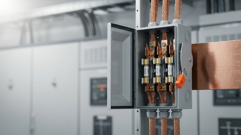
💡 Practical Summary: To tell a PT from a CT, look at the nameplate; if it shows a "voltage ratio," it's a PT, and if it shows a "current ratio," it's a CT. You can quickly spot the differences between a PT and a CT visually: PTs have distinct high-voltage terminals, while CTs feature a pass-through hole or thick conductors.

2. Core Parameters: Why Will Interchanging Them Cause Immediate Failure?
Two main factors of PTs and CTs are magnetic flux density headroom and conductor thickness. Even if we ignore their design goals, switching them will cause problems.
• Magnetic Flux Density Headroom: CT Can Withstand "30x Surge," PT Only "1.9x Fluctuation"
Magnetic flux density headroom is the space that allows equipment to handle magnetic field surges; it’s an important safety measure. A very strong magnetic field can make the core "saturate," like a clogged pipe, which not only causes wrong measurements but can also damage the equipment.
A PT's magnetic flux density headroom is quite limited. Grid voltage changes usually stay within ±20%, and in rare cases, it must endure 1.9 times the rated voltage; for example, a 10kV PT can handle up to 19kV. Using a PT instead of a CT can lead to problems; during a short circuit, the current may spike, reaching 30 times the rated amount, which will exceed the PT's limit in a short time, causing core saturation and potentially burning out the windings.
A CT’s magnetic flux density headroom is quite large. During a line short circuit, current can spike to 30 times the rated value; for example, a 1000A line could see 30,000A. Therefore, protection-grade CTs are designed to handle this 30x surge. Using a CT instead of a PT will greatly reduce voltage measurement accuracy; the error could exceed 10% because of the large magnetic field buffer space.
• Conductor Thickness: "Thin wire" can't handle high current. "Thick wire" linked to high voltage may short-circuit.
Conductor thickness depends on the "rated current." This is the main reason they can't be swapped.
A PT's primary side conductor is very thin, measuring just 0.1-0.5mm², like a hair. This is because the current in high-voltage lines is small, typically in milliamperes, so a thin wire works just fine. Using a PT instead of a CT can cause problems; a large current, often hundreds of amperes, will flow through the thin wire, which can burn the wire out quickly, much like having too much current through a thin wire.
A CT's primary side conductor is very thick, usually 50mm² or more, like a finger. This design is needed to handle large currents. Using a CT instead of a PT can create problems; the thick conductor has very low impedance, so when it's connected to a high-voltage line, it can cause a direct short circuit, similar to connecting live and neutral wires with a thick conductor.
⚠️ Real-World Case: A substation once mistakenly connected a PT in place of a CT to a 10kV line. In just 3 seconds after closing the breaker, the PT's main conductor melted, which caused the line to trip and led to a 2-hour power outage. The extreme heat almost started a fire, emphasizing the critical importance of adhering to electrical safety protocols.
3. Insulation Design: Different Scene Adaptations, Risk of Electric Shock When Interchanged

Insulation performance (preventing high-voltage leakage) is the lifeline of electrical equipment. However, the insulation designs of PTs and CTs prioritize different aspects, and interchanging them can lead to electric shock or equipment damage.
• PT's Insulation: Focus on "Withstanding High Voltage"
A PT's primary side connects directly to high-voltage lines, so the core of its insulation design is to "withstand high voltage." For instance, a 10kV PT must withstand 30kV power frequency voltage (simulating normal operating voltage stress) and 75kV lightning impulse voltage, typically complying with international standards like the IEC 61869 series.
Structurally, PTs often use epoxy resin casting or oil-immersed insulation, ensuring no leakage risk between the high-voltage side and the grounded secondary side.
• CT's Insulation: Balancing "High Voltage Resistance + Impact Resistance"
While a CT may also connect to high-voltage lines, its insulation must also withstand "electrodynamic forces during short circuits" because of the large primary current. When currents are extremely high, conductors generate repulsive forces that can tear insulation.
In low-voltage applications (e.g., 400V), a CT's insulation rating is typically 660V, which is higher than the line voltage, providing sufficient buffer. In high-voltage applications, a CT's insulation level is comparable to a PT of the same voltage, but its windings are more securely fastened to prevent them from being torn apart by electrodynamic forces.
💡 Practical Summary: The insulation design of PTs and CTs is tailored only for their specific applications. Interchanging them carries two types of risks: when a PT replaces a CT, its insulation might be torn apart by powerful electrodynamic forces; when a CT replaces a PT, its insulation might not withstand the high voltage, leading to leakage and potential electric shock accidents.
4. FAQ: 3 Most Commonly Encountered Questions in Practice
• How can I quickly differentiate between a PT and a CT during routine inspections?
Check the Nameplate: A PT nameplate typically shows "XXkV/100V" (voltage ratio), while a CT shows "XXA/5A" (current ratio).
Inspect Wiring: The high-voltage side of a PT usually has distinct insulated terminals, whereas a CT's primary side often features a pass-through hole or thick conductors.
Observe Purpose: A PT is typically connected to voltage busbars (like copper bars at the top of a switchgear), while a CT is always connected in series with the current circuit (like at the cable outgoing end).
• If a PT and CT are mistakenly interchanged, what should be done immediately?
Immediately Disconnect Power: Regardless of whether any abnormalities are apparent, cut off the upstream breaker first to prevent fault escalation or cascading effects.
Inspect Equipment Appearance: Carefully check the transformer's exterior for any smoke or burn marks, and use an infrared thermometer to measure its temperature; if it exceeds 60℃, the equipment is damaged and must be taken out of service immediately.
Contact Professional Personnel: Do not attempt to re-energize the circuit; it is crucial to have qualified electrical maintenance personnel inspect the insulation and winding status of the equipment.
• When selecting transformers, besides parameters, what other application details should be considered?
Outdoor Applications: For transformers installed outdoors, select models with waterproof casings, such as silicone rubber-clad CTs or oil-immersed PTs.
High Harmonic Environments: In environments with high harmonics, such as solar power plants, choose "wide-band transformers" to ensure accurate measurement of harmonic currents or voltages and avoid measurement distortion.
Older Substations: When upgrading or replacing equipment in older substations, prioritize models that are easy to maintain, such as plug-in CTs, which facilitate future replacement and servicing.

5. Conclusion: Remember These 3 Points, and You'll Never Make a Mistake
The correct use of high-voltage instrument transformers is the cornerstone of grid safety.
• Distinct Core Functions: A PT is a "high-voltage to low-voltage metering tool," and a CT is a "high-current to low-current monitoring tool"; their design objectives make them non-interchangeable. • Extreme Interchange Risks: Using a PT in place of a CT will lead to equipment burnout, while using a CT in place of a PT could cause a line short circuit or inaccurate measurements, potentially triggering electric shock accidents and widespread power outages. • Simple Practical Differentiation: By checking the voltage or current ratio on the nameplate and observing the wiring method, you can easily distinguish between a PT and a CT in just two seconds.
If you encounter specific issues during instrument transformer selection or substation operation and maintenance (e.g., you can't distinguish whether a particular piece of equipment is a PT or a CT, or you need to determine the cause of a fault), feel free to contact Weishoelec for support.
Technical Support & Inquiries
Technical Consulting: +86-0577-62788197 (Weekdays 9:00 AM - 6:00 PM EST)
WhatsApp: +86 159 5777 0984
Email: [email protected]
Letting professional tools perform their specialized functions is key to safeguarding the first line of defense for grid safety.