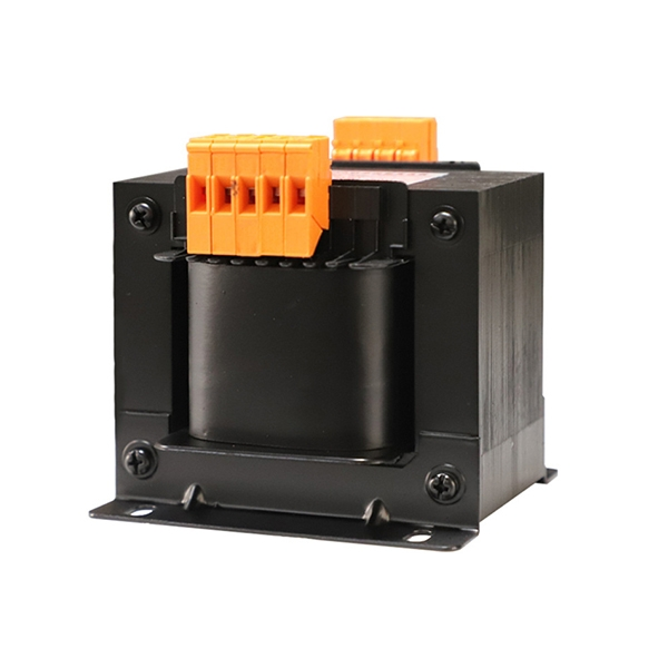
Understanding Control Transformer Parameters
Before learning exactly how to test a control transformer, you must first understand its core operational parameters. Conducting accurate diagnostic tests requires a solid grasp of how the unit functions within your power supply system.
Key Transformer Terminology
To effectively troubleshoot and maintain your equipment, familiarize yourself with these essential terms:
| Term | Definition |
|---|---|
| Primary Winding | The coil that receives the input voltage from the main power supply. |
| Secondary Winding | The coil that delivers the stepped-down or stepped-up output voltage to the load. |
| Turns Ratio | The ratio of the number of turns in the primary winding to the number of turns in the secondary winding. |
| Load Capacity | The maximum power (measured in VA) the transformer can safely deliver. |
Common Causes of Transformer Failure
Transformers are robust, but they are not immune to damage. Recognizing the root causes of failure helps in implementing effective routine maintenance.
Overloading: Drawing more current than the transformer is rated for leads to severe overheating.
Voltage Spikes: Sudden surges in the power supply can degrade insulation and cause a blown fuse.
Environmental Factors: Excessive moisture, dust accumulation, and extreme ambient temperatures accelerate wear and tear.
Vibration: Continuous mechanical vibration can loosen connections and damage internal components.
Visual and Physical Inspection
Always begin your diagnostic tests with a thorough visual and physical inspection. This step often reveals obvious faults before you even touch a multimeter.
Look for Discoloration: Check the exterior casing and coils for burn marks, melted insulation, or dark spots indicating overheating.
Smell for Burnt Components: An acrid, burning odor is a clear sign of an internal short or melted wiring.
Inspect Connections: Ensure all terminal screws are tight and that there are no frayed wires or corroded ground leads.
Check for Physical Damage: Examine the mounting brackets and casing for cracks, dents, or signs of moisture ingress.
How to Test a Control Transformer Using a Multimeter

When you need to troubleshoot transformer issues, a standard multimeter is your most practical tool. Performing routine maintenance and basic diagnostic tests ensures your control panels and industrial equipment run without unexpected downtime. Let’s break down the exact, straightforward process I use to get accurate readings and isolate faults.
Step 1: Disconnect Power and Isolate the Transformer
Safety is the non-negotiable first step. Never attempt to test winding resistance or connections on a live circuit.
Cut the power supply: Before touching any terminals, shut off the main power. Depending on your facility’s scale, this might involve locking out a local breaker or operating an industrial outdoor disconnect switch for the main feed.
Isolate the unit: Disconnect the wires leading to both the primary winding and the secondary winding.
Visual inspection: Look for an obvious blown fuse, burnt terminal blocks, or carbon tracking.
Check downstream components: If the transformer controls heavy loads, ensure you’ve properly isolated any connected relays or a vacuum contactor to prevent back-feeding.
Step 2: Test the Primary Input Voltage
Before assuming the transformer is bad, verify that it is actually receiving the correct power from the line.
Set the meter: Turn your multimeter to the AC voltage setting. Leave the ohms setting alone for now, as that is strictly used for dead-circuit winding resistance checks.
Measure incoming power: Safely restore power to the supply lines and place your probes across the incoming leads.
Analyze the reading: The voltage should match the facility’s expected supply. If you read zero or a severely degraded voltage, your problem is upstream in the power supply, and the transformer is likely fine.
Step 3: Measure the Secondary Output Voltage
Once you confirm the primary voltage is solid, it is time to check what the transformer is outputting.
Perform an open-circuit test: Keep the load disconnected to measure the raw output.
Probe the terminals: Measure the AC voltage directly across the secondary winding terminals.
Expected outcome: You should see a reading that is slightly higher than the transformer’s stated nameplate rating. If you get zero volts, the internal coils have failed, and the unit must be replaced.
Step 4: Test the Transformer Under Load
A transformer might pass an open-circuit test but fail the moment it has to do actual work. The real proof is testing its performance while driving a load.
Reconnect the circuit: Safely power down the system, reconnect your control circuits, and turn the power back on.
Check the voltage under load: Take another reading at the secondary terminals while the connected devices are pulling current.
Evaluate the voltage drop: A minor voltage drop is completely normal. However, if the voltage tanks below acceptable operating levels, the transformer is either failing internally or your control circuit is drawing excessive current. This diagnostic approach is very similar to electric motor testing, where you check for excessive amp draw to find the root cause of a system failure.
Advanced Transformer Testing Methods
When you are figuring out how to test a control transformer beyond basic voltage checks, you need to run advanced diagnostic tests. These are essential during a commissioning test or as part of your routine maintenance schedule to ensure long-term reliability.
Open-Circuit and Short-Circuit Tests
These two tests help us pinpoint exactly where a transformer is losing efficiency.
Open-circuit test: We leave the secondary winding open and apply standard voltage to the primary winding. This accurately measures core losses (iron losses).
Short-circuit test: We short out the secondary winding and apply a low voltage to the primary until full load current flows. This measures copper losses within the windings.
Insulation Resistance Testing
Insulation inevitably degrades over time due to heat and stress. We use a megohmmeter to test the resistance between the windings and the core.
Connect the test cables between the individual windings and the ground leads.
A high resistance reading is good; a low reading means the insulation is failing and a short is likely.
Just like understanding how a vacuum circuit breaker works is crucial for overall system protection, verifying your control transformer’s insulation prevents catastrophic grounding faults in your panels.
Turns Ratio and Power Factor Testing
To confirm the transformer is stepping down voltage exactly as designed from the factory, we perform turns ratio testing.
| Test Type | What It Checks | Why It Matters |
|---|---|---|
| Turns Ratio | The exact ratio of primary to secondary turns (similar to verifying a CT ratio). | Ensures the transformer delivers the correct output voltage for your specific load. |
| Power Factor | The dielectric loss of the insulation system. | Detects hidden moisture, dirt, or degradation inside the transformer before it fails. |
Interpreting Test Results and Troubleshooting

Once we gather our readings, we need to decode them to successfully troubleshoot the transformer. Knowing what is normal and what points to an impending failure saves time, prevents downtime, and keeps your systems running safely.
How to Read Voltage Outcomes
When figuring out how to test a control transformer, reading the voltage correctly is the core task. We compare the primary winding input and the secondary winding output directly against the numbers on the manufacturer’s nameplate.
Baseline Match: Your secondary voltage should closely match the rated output. If it is significantly higher or lower, the transformer is failing.
Checking Voltage Under Load: A slight voltage drop when the attached machine is running is perfectly normal. However, a massive dip in voltage under load indicates the transformer is weak, internally damaged, or improperly sized for the application.
Checking for Shorts and Grounding Issues
If your control panel keeps tripping breakers or you constantly have to replace a blown fuse in the circuit, a short or ground fault is usually to blame. To find the fault, we switch the multimeter to the ohms setting.
Test Winding Resistance: Check the continuity between the primary and secondary coils. We want to see infinite resistance (often displayed as “OL” on digital screens).
Test the Ground Leads: Place one probe on a coil terminal and the other directly on the metal chassis. If the meter shows low ohms instead of an open circuit, the internal insulation has failed, and the unit is shorting directly to ground.
Common Mistakes Made During Testing
Even seasoned pros can make simple errors during routine maintenance and diagnostic tests. Avoid these frequent pitfalls to get an accurate reading:
Testing with Live Power: Trying to measure winding resistance or run an open-circuit test while the main power supply is still active. This will instantly ruin your meter and risk severe injury.
Skipping the Load Test: Relying purely on no-load readings. A transformer might look fine resting but fail immediately when asked to do actual work.
Misreading the Meter: Glancing too quickly at older analog ammeters or setting a digital multimeter to the wrong range, which leads to completely false s about the electrical health of the system.

Control Transformer Maintenance and Safety
When learning how to test a control transformer, understanding the testing process is only half the battle. Implementing routine maintenance and strict safety protocols ensures your equipment lasts longer and your team stays safe.
Temperature-Rise Testing Strategies
Transformers naturally generate heat, but excessive heat is a major red flag. Temperature-rise testing is one of the most critical diagnostic tests I rely on to evaluate transformer health under actual working conditions.
Monitor Under Load: Run the transformer at full capacity and measure the temperature of the primary winding and secondary winding.
Check Ventilation: Ensure the enclosure has adequate airflow. Poor ventilation artificially inflates temperature readings.
Look for Overloading: If the temperature spikes beyond the manufacturer’s rating, the transformer is likely overloaded. This excessive heat can degrade insulation rapidly and often leads to a blown fuse. If your system frequently experiences overcurrent issues, upgrading your protective hardware, such as installing reliable high-voltage drop-out fuses, can prevent catastrophic equipment failure.
Golden Rules for Safe Transformer Testing
Electricity is unforgiving. Whether you are performing a factory acceptance test or routine troubleshooting, safety must always come first. Here are the golden rules I strictly follow:
De-energize Everything: Never assume a circuit is dead. Always disconnect the power supply and verify with your multimeter before touching any terminals.
Isolate the Transformer: Remove all external connections. Testing a transformer while it is still wired into the broader circuit will give you false readings and poses a severe shock hazard.
Discharge Capacitors: If your system includes capacitors, ensure they are fully discharged before you begin your diagnostic tests.
Wear Proper PPE: Always wear insulated gloves and safety glasses.
Double-Check Meter Settings: Before probing the terminals, confirm your multimeter is on the correct setting (e.g., AC voltage vs. ohms setting). Using the wrong setting can damage your meter or cause an arc flash.