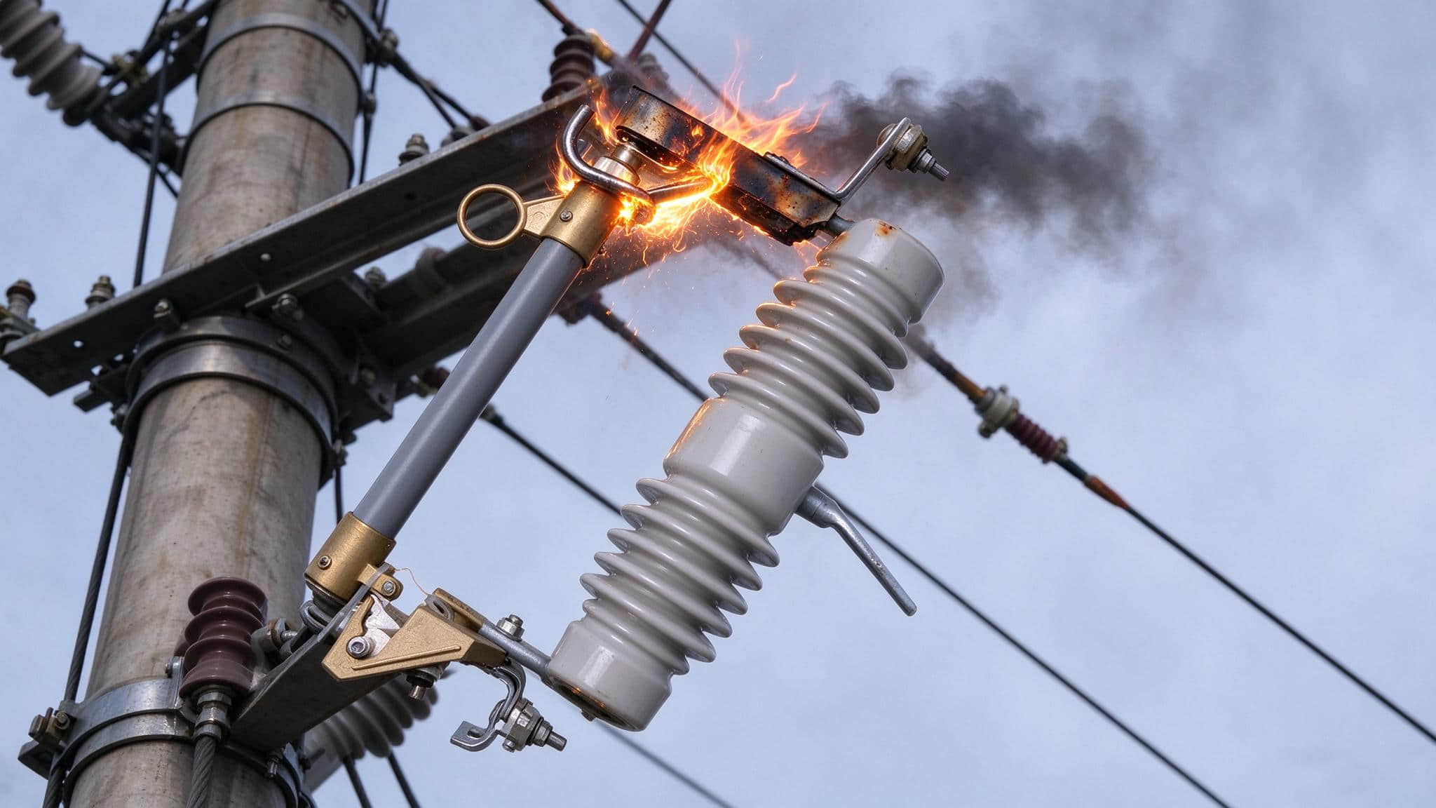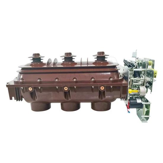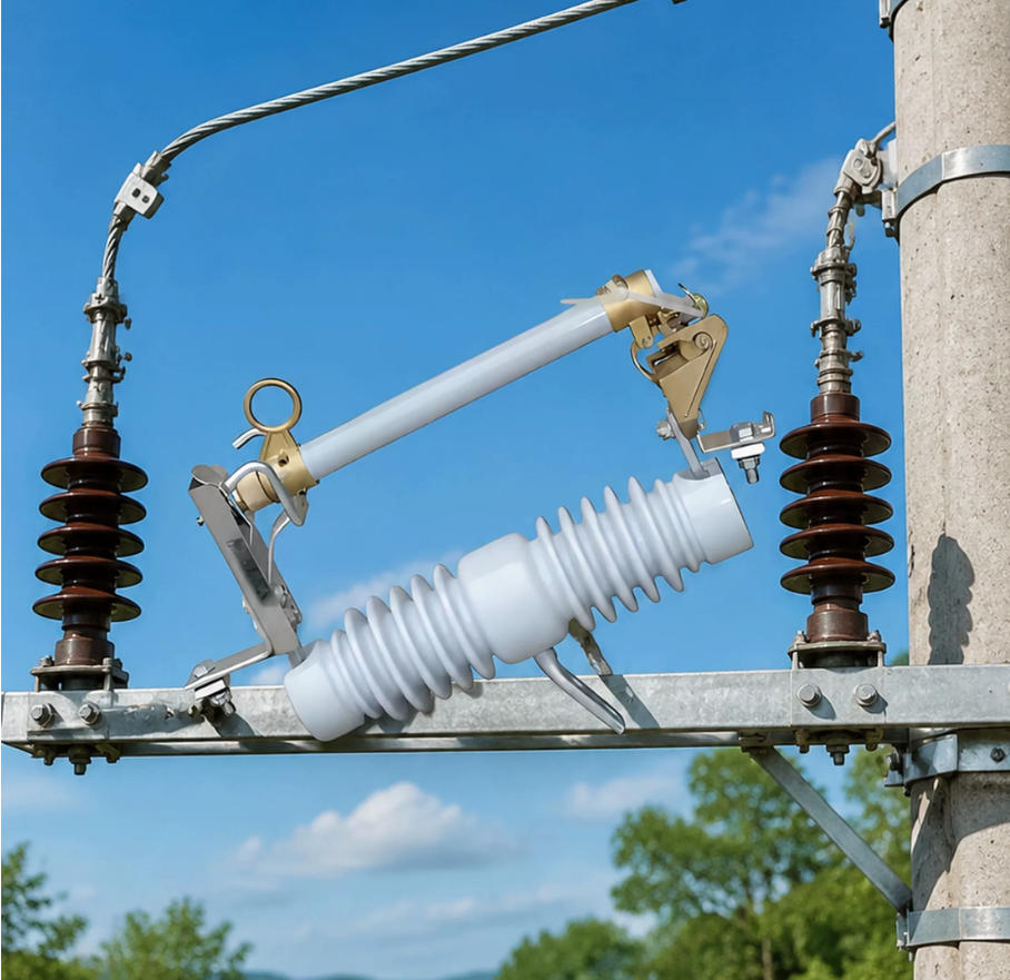
Choosing between an RW12-10/100A and an RW12-10/200A drop-out fuse looks simple on paper, but in real projects it is one of the most frequently misunderstood selections in 10kV distribution networks.
The mistake usually starts with one wrong assumption: many buyers think 100A or 200A is the fuse link melting current. It is not. In an RW12-10 dropout fuse, 100A or 200A refers to the continuous current-carrying capacity of the fuse cutout base assembly, including the body, contacts, and fuse tube structure.
This point matters in quoting, engineering, and field reliability. If you confuse the base rating with the fuse link current, you can easily overspecify the product, raise project cost, or create a mismatch between transformer protection and the actual cutout structure.
This guide explains the RW12-10 dropout fuse 100A vs 200A selection in a practical way, using real transformer data, line application logic, and common industry habits seen in utility, rural grid, and industrial distribution projects.
If you are sizing a cutout for a transformer, branch line, or main distribution point, the goal is simple: choose the right base first, then choose the right fuse link separately.
What 100A vs 200A Really Means in an RW12-10 Drop-out Fuse
In an RW12-10 drop-out fuse, the 100A or 200A marking describes the long-term allowable current of the cutout base. That includes the mechanical and conductive parts that carry current continuously in outdoor service.
It does not mean the fuse link inside is always 100A or 200A. A 100A base can use a much smaller fuse link, such as 10A, 20A, 40A, or 63A, as long as the selected link is within the base limit and matches the holder design.
Likewise, a 200A base can also use small fuse links. The difference is that the 200A base has a larger conductive cross-section, stronger contact structure, larger terminals, and usually a higher interrupting capacity ceiling.
That is why a customer asking for a “20A dropout fuse” should not automatically receive a quote for a 200A base. In many routine 10kV transformer applications, a 100A base + 20A fuse link is the correct and more economical answer.
Why Customers Often Misjudge RW12-10 100A vs 200A Selection
In daily sales and procurement work, the most common confusion is between cutout base rating and fuse link rating.
For example, a buyer may say, “I need a 30A dropout fuse for a 10kV transformer.” What they often mean is the fuse link should be 30A. That does not mean the base must be 30A, 100A, or 200A by the same logic.
Another frequent mistake is assuming transformer capacity directly maps to base current number. A 200kVA transformer does not mean a 200A cutout base. In fact, on the 10kV side, a 200kVA transformer draws only about 11.5A rated current.
That is why correct quoting must separate two decisions:
Decision 1: Is the cutout base 100A or 200A?
Decision 2: What fuse link current should be installed?
When this distinction is clear, selection becomes faster, safer, and more cost-effective.
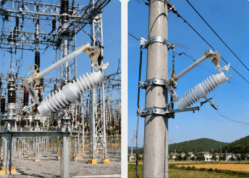
RW12-10 100A vs 200A: Core Differences Table
The practical difference between the two models is not just the number on the nameplate. It affects continuous thermal performance, terminal size, mechanical robustness, and often fault-duty suitability.
Table: RW12-10/100A vs RW12-10/200A Technical Comparison
| ITEM | RW12-10/100A | RW12-10/200A |
|---|---|---|
| Continuous current capacity of cutout base | 100A | 200A |
| Compatible fuse link range | 1A to 100A | 1A to 200A, including larger high-current tube structure |
| Typical interrupting capacity | Typically 6.3kA or 8kA | Typically 8kA or 12.5kA, with higher upper limit options |
| Contacts and terminals | Standard size conductive parts | Reinforced copper contacts, larger terminals, heavier conductive section |
| Typical application | Small distribution transformers, rural transformers, overhead branch lines | Larger transformers, main branches, heavier load lines, concentrated supply points |
| Relative price | Lower | Higher |
In short, 100A is the standard economical choice for most common pole-mounted distribution transformer jobs. 200A is the stronger structure for higher load margin, larger conductors, and installations that need more thermal and mechanical headroom.
How to Size RW12-10 Drop-out Fuse for 10kV Transformer Protection
If your target is transformer protection, the right process is straightforward. First calculate the transformer high-voltage current. Then select the cutout base. After that, choose the fuse link separately.
This is the most reliable way to answer the question: how to size RW12-10 drop-out fuse for transformer protection.
Transformer High-Voltage Current Formula
For a 10kV distribution transformer, the high-voltage side rated current can be estimated by:
I = S / (√3 × 10kV)
Where:
I = transformer high-voltage rated current in amperes
S = transformer capacity in kVA
For practical field use, this formula gives quick and sufficiently accurate reference values for cutout and fuse link sizing.
Table: Real-World 10kV Transformer Current Examples
| TRANSFORMER CAPACITY | APPROXIMATE HV CURRENT AT 10KV | COMMON BASE CHOICE |
|---|---|---|
| 50kVA | 2.9A | RW12-10/100A |
| 100kVA | 5.8A | RW12-10/100A |
| 160kVA | 9.2A | RW12-10/100A |
| 200kVA | 11.5A | RW12-10/100A |
| 315kVA | 18.2A | RW12-10/100A |
| 400kVA | 23.1A | RW12-10/100A |
| 500kVA | 28.9A | Usually RW12-10/100A |
| 630kVA | 36.4A | Often RW12-10/200A |
| 800kVA | 46.2A | Usually RW12-10/200A |
These numbers immediately show why so many projects do not require a 200A base. Even a 500kVA transformer only draws about 28.9A on the 10kV side under rated conditions.
That is also why experienced engineers do not size the base by transformer kVA number alone. They consider continuous loading, fault level, terminal size, utility standards, and installation practice.
When to Choose RW12-10/100A for Transformer Protection
For most standard 10kV distribution transformers, RW12-10/100A is the default choice up to 500kVA.
This is not a theory-only recommendation. It reflects long-standing field practice in rural electrification, public distribution networks, and typical utility transformer installations.
Common capacities such as 50kVA, 100kVA, 160kVA, 200kVA, 315kVA, 400kVA, and 500kVA are routinely protected with a 100A base, while the fuse link is selected separately to match the transformer characteristics.
This approach is widely used because it delivers the right balance of:
Technical adequacy
Lower hardware cost
Simpler standardization
Sufficient mechanical and thermal performance for common loads
In other words, for ordinary single distribution transformer service, a 100A base is not a compromise. It is often the correct engineering choice.
Typical Fuse Link Selection for Transformers on a 100A Base
Once the base is selected, the fuse link should be sized according to the transformer high-voltage rated current, while allowing for transformer energization inrush.
A widely used practical rule is:
For transformers up to 100kVA: select fuse link current at about 2 to 3 times the transformer HV rated current
For transformers above 100kVA: select fuse link current at about 1.5 to 2 times the transformer HV rated current
This is not random. Small transformers can have pronounced magnetizing inrush relative to rated current, so a slightly higher multiple helps avoid nuisance fuse operation. Larger units still need inrush tolerance, but protection coordination usually benefits from a tighter multiplier.
Here are practical examples:
100kVA transformer: HV current ≈ 5.8A, common fuse link may be around 12A to 16A depending on system practice
200kVA transformer: HV current ≈ 11.5A, common fuse link may be around 16A to 25A
315kVA transformer: HV current ≈ 18.2A, common fuse link may be around 25A to 40A
500kVA transformer: HV current ≈ 28.9A, common fuse link may be around 40A to 63A
Exact link values should still consider coordination with upstream protection, transformer manufacturer guidance, local utility standards, ambient temperature, and expected cold-load pickup behavior.
But the important principle never changes: the fuse link current and the cutout base current are two different selections.
When to Choose RW12-10/200A for Transformer Protection
A 200A base becomes the better choice when the installation moves beyond standard small and medium transformer service.
In practice, choose RW12-10/200A when one or more of the following conditions apply:
Transformer capacity is above 500kVA, such as 630kVA or 800kVA
Long-term operating load current is near or above 80A at the installation point
Available short-circuit current is high and a stronger cutout structure or higher breaking duty is desired
Project drawings specify 200A construction, larger terminals, or heavier copper contacts
Conductor size and connection layout make larger terminals preferable for safe installation
For example, a 630kVA industrial transformer may only have a rated HV current of about 36.4A, which seems low relative to a 100A base. But many engineers still prefer a 200A base because the site may involve larger conductors, stronger mechanical demands, harsher thermal conditions, and higher network fault levels.
That is a good example of why selection should not be made from transformer current alone.
Common Selection Mistake: 200kVA Does Not Mean 200A Base
This misunderstanding is extremely common in both purchasing and first-time technical sales.
A customer sees 200kVA transformer and assumes 200A cutout base. That is incorrect.
A 200kVA transformer at 10kV has only about 11.5A rated HV current. In the vast majority of distribution transformer projects, it is still matched with a 100A RW12-10 base and an appropriately selected fuse link.
The same logic applies to 315kVA, 400kVA, and even 500kVA installations. Industry practice still commonly uses the RW12-10/100A base for these sizes.
If you skip this understanding and quote 200A bases by default, the customer usually pays more without gaining meaningful protection benefit.
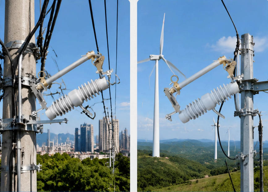
RW12-10 Fuse Current Rating for Distribution Line Applications
The RW12-10 fuse current rating for distribution line applications should be selected differently from transformer-only protection. In line applications, the key factors are the maximum continuous load current, branch importance, supply topology, and whether multiple transformers are fed through the same section.
For overhead distribution, the cutout often protects branch take-offs, sectionalized line points, or taps serving several downstream loads. In those cases, the decision between 100A and 200A is driven less by a single transformer kVA and more by the actual feeder behavior.
When 100A Base Is Enough for Overhead Branch Lines
As a practical rule, if the branch line maximum continuous load is 80A or below, a 100A base is generally sufficient.
This covers many common overhead branch circuits in rural networks, village electrification, agricultural loads, and light commercial distribution points.
Why use 80A as the practical threshold rather than 100A exactly? Because engineers normally keep some thermal margin between expected operating current and the base continuous current rating. This helps with hot weather, load growth, contact aging, and system imbalance.
Typical 100A base line applications include:
Single rural branch feeder
One or two small distribution transformers
Agricultural irrigation branch with moderate diversified load
Village side street or small commercial branch
When 200A Base Is Better for Main Branches and Heavier Loads
When line loading rises into the 80A to 200A range, the RW12-10/200A base is usually the safer and more durable option.
This is especially true for:
Main branch lines
Backbone branch circuits
Lines supplying multiple transformers
Dense load clusters
Industrial or commercial expansions
For instance, if one overhead branch feeds three 315kVA transformers with coincident loading that pushes the branch current toward or above 80A during peak season, engineers typically move to a 200A base. The upgrade is not just about nominal current. It is also about stronger terminals, lower temperature rise at the contact points, and a better safety margin for long-term service.
10kV Outdoor Dropout Fuse 100A and 200A Difference in Other Applications
The 10kV outdoor dropout fuse 100A and 200A difference also matters in applications beyond standard transformer and overhead branch protection.
Examples include:
Capacitor banks
Cable branch connections
Distribution nodes with larger conductor terminations
Installations requiring stronger thermal stability
In capacitor bank service, inrush and switching conditions may lead engineers to prefer a sturdier cutout structure, especially where conductor sizes are larger or where repeated thermal cycling is expected.
In cable branch applications, the physical terminal size can be just as important as current rating. A larger 200A terminal often simplifies installation of heavier lugs and improves contact reliability.
For small agricultural transformer points, however, these benefits may not justify the higher cost. In such cases, the 100A design remains the logical choice.
Choosing the Right RW12-10 Cutout Fuse for Power Distribution: A 2-Step Method
The simplest way to improve accuracy and quoting speed is to use a 2-step method. This is the most dependable approach for choosing the right RW12-10 cutout fuse for power distribution.
Step 1: Select the Cutout Base Rating First
Choose 100A or 200A based on the cutout structure requirement, not the fuse link value.
Check these four points first:
Maximum long-term operating current
Transformer size range or total downstream load
Drawing or customer specification
Short-circuit duty and desired interrupting capacity margin
As a rule of thumb:
Single transformer up to 500kVA: start with 100A
Transformer above 500kVA: move toward 200A
Long-term line load above 80A: prefer 200A
Higher fault level or larger terminals specified: prefer 200A
Step 2: Select the Fuse Link Separately
After the base is fixed, choose the fuse link according to transformer rated current or line load current. A common field range is roughly 1.5 to 2.5 times the relevant rated current, with some smaller transformers going up to 3 times to avoid inrush-related nuisance operation.
One rule must always be respected: the fuse link current must never exceed the base rating.
Examples:
100A base can use 10A, 20A, 40A, 63A, 80A, or 100A fuse links as appropriate
200A base can use 20A, 40A, 63A, 100A, 125A, 160A, or 200A fuse links if compatible with the assembly
This separation of decisions is the main reason experienced engineers quote faster and more accurately than those relying on guesswork.
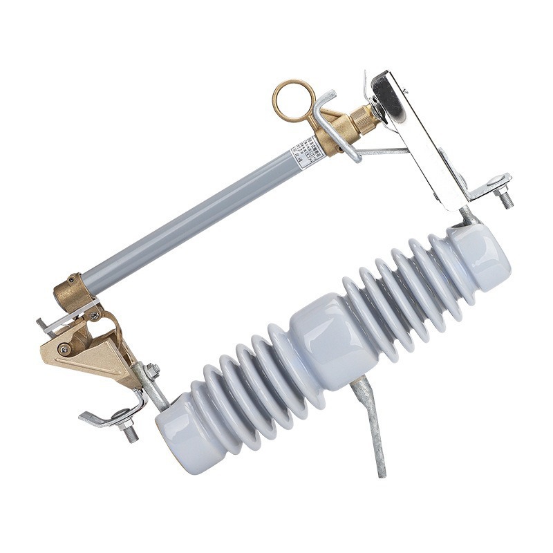
Fast Decision Rules for RW12-10 Dropout Fuse 100A vs 200A Selection
For sales teams, procurement staff, and site engineers, these shortcut rules work well in everyday projects.
Table: Quick Selection Guide
| PROJECT CONDITION | RECOMMENDED CHOICE |
|---|---|
| Single transformer ≤500kVA | Default RW12-10/100A |
| Single transformer >500kVA | RW12-10/200A |
| Long-term load >80A | Prefer RW12-10/200A |
| Customer asks for “20A dropout fuse” only | Recommend 100A base + 20A fuse link unless 200A structure is specified |
| Drawing specifies 200A, large terminals, or higher breaking capacity | Quote RW12-10/200A |
These rules are especially useful during initial inquiries when complete design data is not yet available.
They help avoid two common errors:
Overselling 200A bases where 100A is enough
Underspecifying a branch or industrial point that actually needs 200A structure
Real-World Selection Examples
Real projects are where selection logic becomes clear. The following cases reflect typical engineering and quotation decisions seen in the market.
Example 1: 100kVA Rural Distribution Transformer
A rural utility installs a single 100kVA, 10/0.4kV pole-mounted transformer to supply homes, small shops, and seasonal irrigation pumps.
The transformer HV current is about 5.8A. In practice, an RW12-10/100A base is the normal economical solution, with a properly selected fuse link such as 12A or 16A depending on the utility standard and inrush policy.
Using a 200A base here rarely adds value. The line conductors are modest, the thermal duty is ordinary, and the budget matters.
Example 2: 500kVA Pole-Mounted Transformer
A contractor quotes protection for a 500kVA outdoor distribution transformer in a suburban feeder extension.
The transformer HV current is about 28.9A. Despite the larger capacity, industry practice still commonly uses an RW12-10/100A base with an appropriately selected fuse link, often in the 40A to 63A range depending on protection coordination.
This is a perfect example of why base rating is not selected by kVA label alone. Even at 500kVA, the 100A base is still very often the standard answer.
Example 3: 630kVA Industrial Transformer
An industrial customer installs a 630kVA transformer near a production line with strong load swings and larger incoming hardware.
The HV current is about 36.4A, which a 100A base might appear able to handle in theory. But in real engineering practice, many teams prefer an RW12-10/200A base here because of:
Larger cable lugs or conductors
Higher expected fault duty
Need for larger contact surfaces
Extra thermal margin for continuous industrial service
In this situation, the 200A structure is not overkill. It is a deliberate reliability choice.
Example 4: Overhead Branch Line Feeding Multiple Transformers
A 10kV overhead branch feeds three downstream transformers: 200kVA, 315kVA, and 315kVA. At seasonal peak, the branch current can approach or exceed 80A.
Even if no single transformer requires a 200A base by itself, the branch application does. Engineers typically specify an RW12-10/200A for stronger structure, larger terminals, and better long-term temperature performance.
This is one of the clearest examples where line application selection differs from single-transformer selection.
FAQ
What is the difference between RW12-10 100A and 200A?
The main difference is the cutout base current-carrying capacity, the supported fuse link range, the structure size of contacts and terminals, and usually the upper interrupting capacity level. A 200A version is physically stronger and intended for heavier duty applications.
Is 100A or 200A the fuse link current?
No. In RW12-10 products, 100A or 200A refers to the base rating. The fuse link current must be selected separately according to transformer protection or line load requirements.
Can a 100A RW12-10 base use a 20A fuse link?
Yes. A 100A base can use a 20A fuse link as long as the fuse link and holder are compatible with the cutout design. This is a very common configuration in transformer protection.
Can a 200A RW12-10 base use a 20A or 40A fuse link?
Yes. A 200A base can also use smaller fuse links such as 20A or 40A, provided the assembly is compatible and the fuse link current stays within the base limit.
Does a 200kVA transformer require a 200A RW12-10 drop-out fuse?
No. Most 200kVA 10kV distribution transformers still use a 100A base with a properly selected fuse link. A 200kVA transformer only draws about 11.5A on the 10kV side at rated load.
When should I upgrade from RW12-10/100A to RW12-10/200A?
You should upgrade when the transformer is above 500kVA, when long-term load current is near or above 80A, when fault level is higher, or when the project specifies larger terminals or 200A construction.
How do I choose the fuse link for transformer protection?
Start with the transformer high-voltage rated current, then select the fuse link at roughly 1.5 to 3 times that current depending on transformer size, inrush behavior, and coordination requirements. Smaller transformers often use a larger multiple than bigger ones.
Is RW12-10/200A always better than RW12-10/100A?
No. It costs more and is unnecessary for most standard small and medium distribution transformer applications. The better choice is the one that matches the actual load, fault duty, and installation requirement.
Get the Right RW12-10 100A or 200A Selection for Your Project
If you want fast and accurate help with RW12-10 dropout fuse 100A vs 200A selection, do not start with guesswork. Start with the project facts.
Send these four inputs:
Transformer capacity or total downstream load
Maximum line load current
Available fault level or required breaking capacity
Drawing requirements, including terminal size or specified 100A/200A structure
With that information, an experienced supplier can quickly recommend the correct RW12-10 base rating and the suitable fuse link current, avoiding both overpricing and underspecification.
Weisho Electric works with practical 10kV distribution applications and understands that a good quote is not just about offering a product number. It is about matching the cutout body, fuse link, fault duty, and installation condition correctly.
If you are comparing options for transformer protection, overhead line branches, or industrial distribution points, Weisho Electric can help you confirm whether you really need RW12-10/100A or RW12-10/200A, and which fuse link will make the system both safe and economical.
Contact us now with your transformer kVA, line current, short-circuit level, and drawing details for a fast recommendation and quotation.