Understanding the difference between a Current Transformer (CT) and a Potential Transformer (PT) is crucial for anyone working with electrical systems. While both are essential for measurement and protection, they serve distinct purposes: CTs measure current by stepping it down to a safer level, whereas PTs reduce high voltage to a manageable level for instruments.
Confusing these two can lead to inaccurate readings or even serious equipment damage. In this article, you will learn the key differences between CTs and PTs, how they work, and when to use each. We will also cover practical wiring diagrams, common errors, and troubleshooting tips to help you confidently select and use these transformers in your power systems.
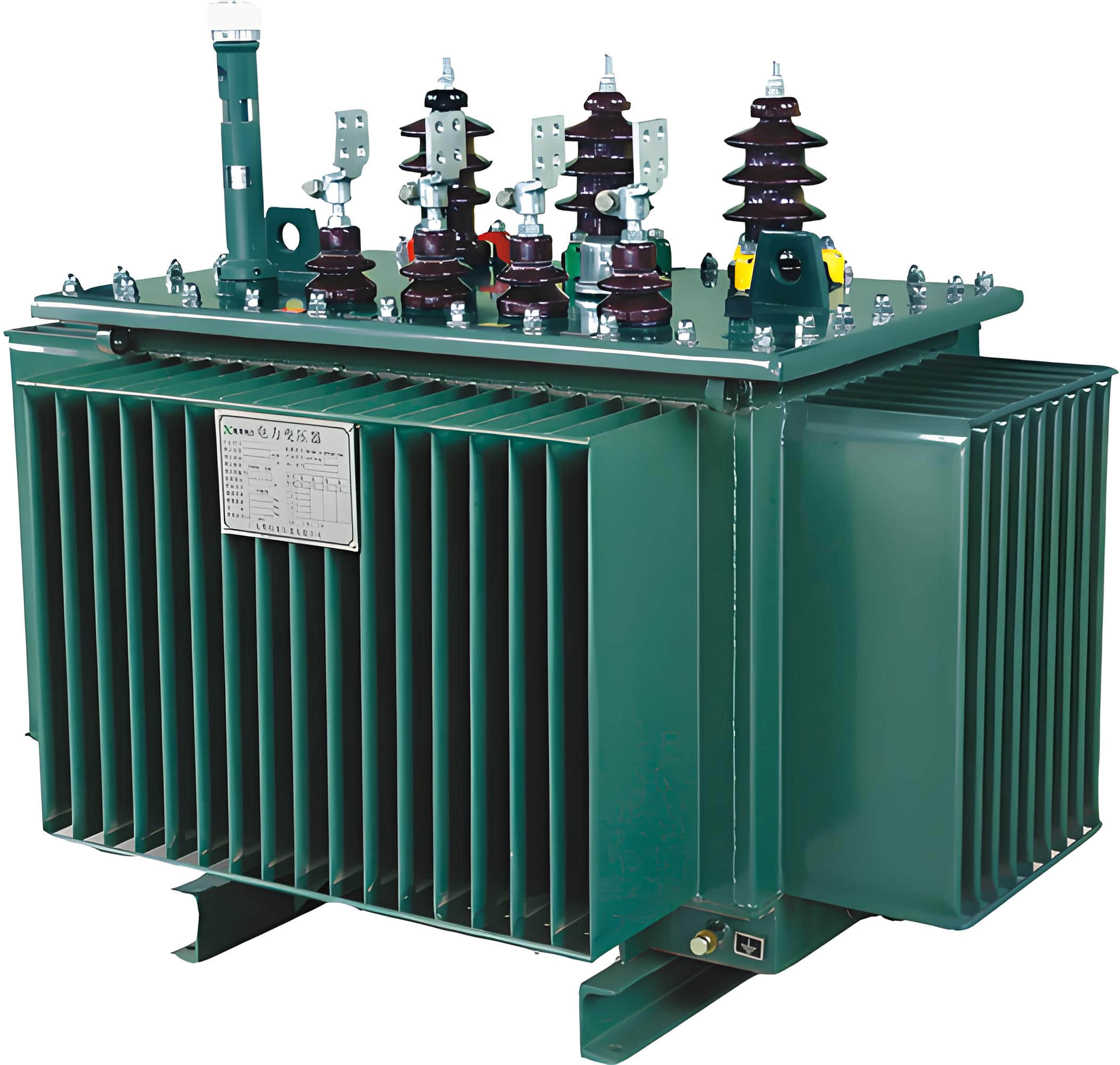
What Is a Current Transformer (CT)?
A CT reduces high currents to safe, measurable levels.
CTs are designed for measuring or monitoring current in high-voltage environments. They work by creating a smaller, proportional current on their secondary side. This current can safely feed into measuring instruments, relays, or meters.
CTs are essential for:
Power system monitoring
Protective relaying
Industrial energy audits
Their accuracy and safety are critical in substations, factories, and any system with large electrical loads.

What Is a Potential Transformer (PT)?
A PT steps down high voltage to a lower level for safe measurement.
Also called a voltage transformer (VT), a PT works similarly to a CT but with voltage. It reduces high voltages to values compatible with standard meters and relays. Like CTs, they ensure isolation between high-voltage circuits and measuring equipment.
PTs are used for:
Voltage metering
Grid monitoring
Voltage protection schemes
They play a vital role in ensuring stable and safe operation in high-voltage systems.

Working Principle: CT vs PT
Both CTs and PTs rely on electromagnetic induction, but their focus differs.
CTs respond to the magnetic field produced by current flow. The primary winding is a conductor carrying the high current, while the secondary produces a lower, proportional current.
PTs have multiple windings and a magnetic core, similar to a standard power transformer. They transform voltage proportionally without altering frequency.
| Feature | CT | PT |
|---|---|---|
| Measures | Current | Voltage |
| Primary Input | High current | High voltage |
| Secondary Output | Scaled-down current | Scaled-down voltage |
| Connection | In series with the load | In parallel with the circuit |

Key Technical Differences
1. Installation Method
CTs are installed in series, PTs in parallel.
Because CTs must carry the full current load, they sit directly in line with the circuit. PTs, however, are wired in parallel since they only need to sense the voltage.
2. Safety Requirements
CTs require shorter secondary circuits; PTs need fuses.
An open CT secondary can create dangerously high voltages. It must always be connected to a burden. PTs, on the other hand, are protected with fuses to prevent faults.
3. Output Range
CTs provide milliamp to amp-level outputs; PTs output volts.
The typical CT output is 1A or 5A. PTs usually output standard voltages such as 110V or 120V for easy measurement.
Applications in Real Systems
CTs and PTs each have specific roles in power networks.
CT Use Case: Power Plant Monitoring
In U.S. hydroelectric facilities, CTs are installed on generator output lines to ensure accurate current measurement and protection against overload.PT Use Case: Grid Voltage Regulation
PTs help utilities in Europe measure line voltage for grid stability. When voltage drifts beyond acceptable limits, systems automatically adjust transformers or tap changers.
Troubleshooting: When Problems Arise
CT Issues
Incorrect polarity leads to wrong measurements
Open secondary causes high voltage hazards
Excessive burden distorts the current ratio
PT Issues
Loose connections cause a voltage drop
Incorrect fuse rating risks equipment damage
Environmental factors (moisture, heat) affect accuracy
Regular inspection and proper installation prevent these issues.
Common Mistakes to Avoid
Many measurement failures stem from basic oversights.
Mixing CTs and PTs in diagrams
Choosing the wrong ratio (e.g., 1000:5 CT for a 500A system)
Not grounding the PT secondary winding
Using CTs for voltage measurement (and vice versa)
Each device has a distinct job. Misapplication reduces reliability and increases risk.

Wiring Diagrams: Correct and Incorrect Connections
Proper wiring ensures accuracy and safety.
Below are simplified diagrams that illustrate typical CT and PT wiring methods, along with common mistakes to avoid.
Correct CT Connection:
Primary: In series with load
Secondary: Connected to the measurement device with the burden
Incorrect CT Example:
Secondary left open: Causes dangerous voltage buildup
Correct PT Connection:
Primary: In parallel with the high-voltage circuit
Secondary: Fused and connected to a voltmeter
Incorrect PT Example:
No fuse on primary side: Risk of transformer burnout
Understanding these diagrams can prevent costly failures.
Choosing the Right Transformer
Base your decision on the variable you need to measure.
Use a CT when measuring current in a live circuit.
Use a PT when measuring voltage in high-voltage systems.
Consider factors like system voltage/current, equipment ratings, and environmental conditions.

FAQs: CTs vs PTs
Q1: Can I use a CT to measure voltage?
No. CTs are designed for current use only. Using them for voltage can damage your system and provide inaccurate data.
Q2: What happens if I leave a CT secondary open?
This can create high voltages, posing a serious risk of electric shock and damaging equipment.
Q3: Are PTs and VTs the same?
Yes. PTs (Potential Transformers) and VTs (Voltage Transformers) are interchangeable terms.
Q4: How do I know the right CT/PT ratio to use?
The ratio should match your system’s primary parameters and measurement device range. Always consult the system specification or a certified technician.
Q5: Do CTs and PTs require maintenance?
Yes. Periodic inspection for wiring integrity, moisture intrusion, and calibration is essential.
Summary
Current transformers and potential transformers serve different but equally important roles in power systems. While CTs reduce current, PTs reduce voltage—both enabling safe, accurate monitoring and protection.
The key takeaway: Choose CTs for current, PTs for voltage. Install them properly, inspect regularly, and always match device specs to your system requirements.
Need help selecting the right transformer for your project? Contact our engineering team for expert advice, wiring diagrams, or system planning support.