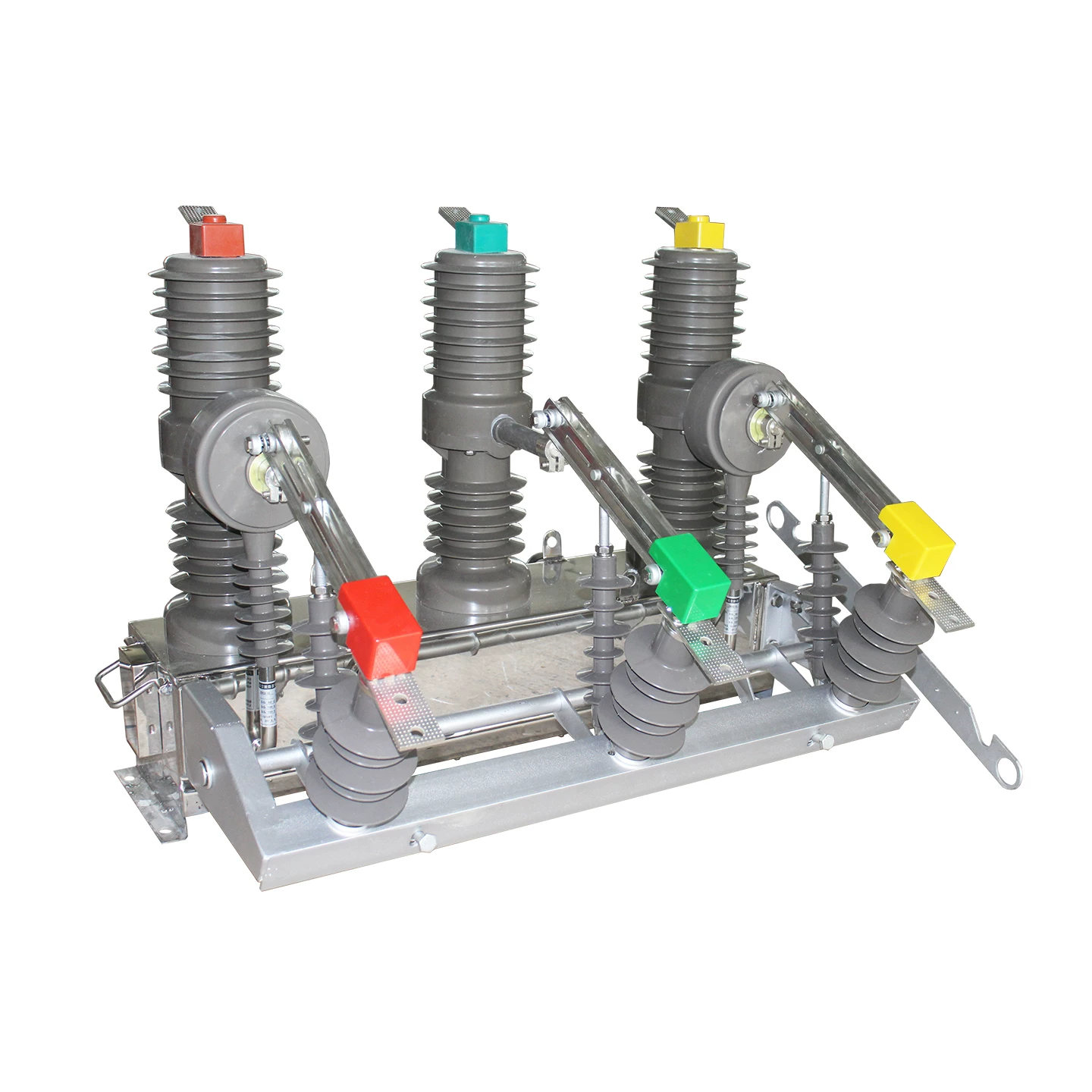
Are current transformers AC or DC?
A current transformer is fundamentally an AC device. It is designed for alternating current measurement, protection, and monitoring, and it does not directly measure steady DC current.
The short answer is simple: if the current is changing with time, a current transformer can work; if the current is steady DC, a standard current transformer will not provide a meaningful continuous output. That is the core of current transformer AC operation.
Why this question matters in real electrical systems
This is not just a textbook distinction. In the field, choosing the wrong sensor can lead to bad data, nuisance alarms, failed protection coordination, or expensive redesigns.
I have seen projects where engineers assumed one sensor could “cover everything,” only to discover late in commissioning that the line was actually DC-dominant. At that point, the current transformer was already installed, the panel was built, and the readings were effectively useless for the intended purpose.
In energy metering, using the wrong sensor means inaccurate billing or misleading power analytics. In commercial buildings and factories, even a small percentage error multiplied across months of load data can distort decisions about efficiency upgrades.
In protection relays, the stakes are higher. Protective schemes rely on current values to trip breakers during overloads, ground faults, or short circuits. CTs are excellent in AC switchgear, but a DC fault monitoring scheme needs a different sensing approach.
In EV systems and battery monitoring, this distinction is critical. Traction battery packs, DC busbars, battery storage cabinets, and charger outputs often involve substantial DC current. A standard CT cannot reproduce the steady current level that battery management or safety systems need.
In solar-plus-storage systems, people sometimes confuse inverter-side AC monitoring with battery-side DC monitoring. On the inverter AC output, a CT may be perfect. On the battery string itself, it is the wrong tool.
That is why the question “can current transformers measure DC?” matters in practical engineering, procurement, and maintenance.
What is a current transformer?
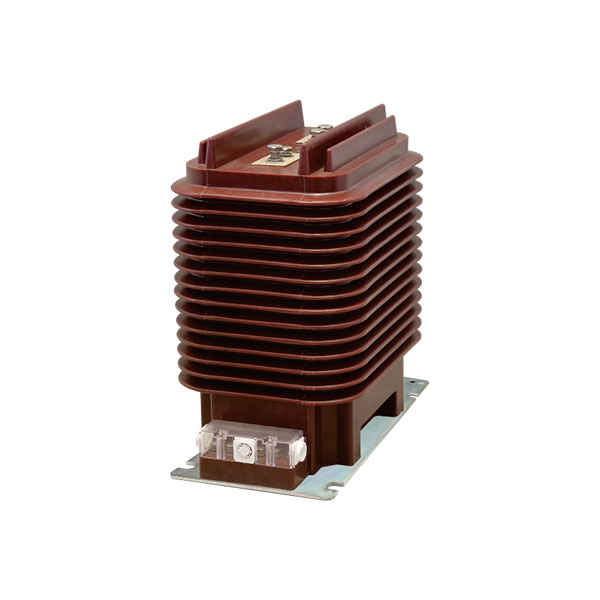
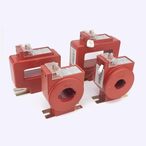
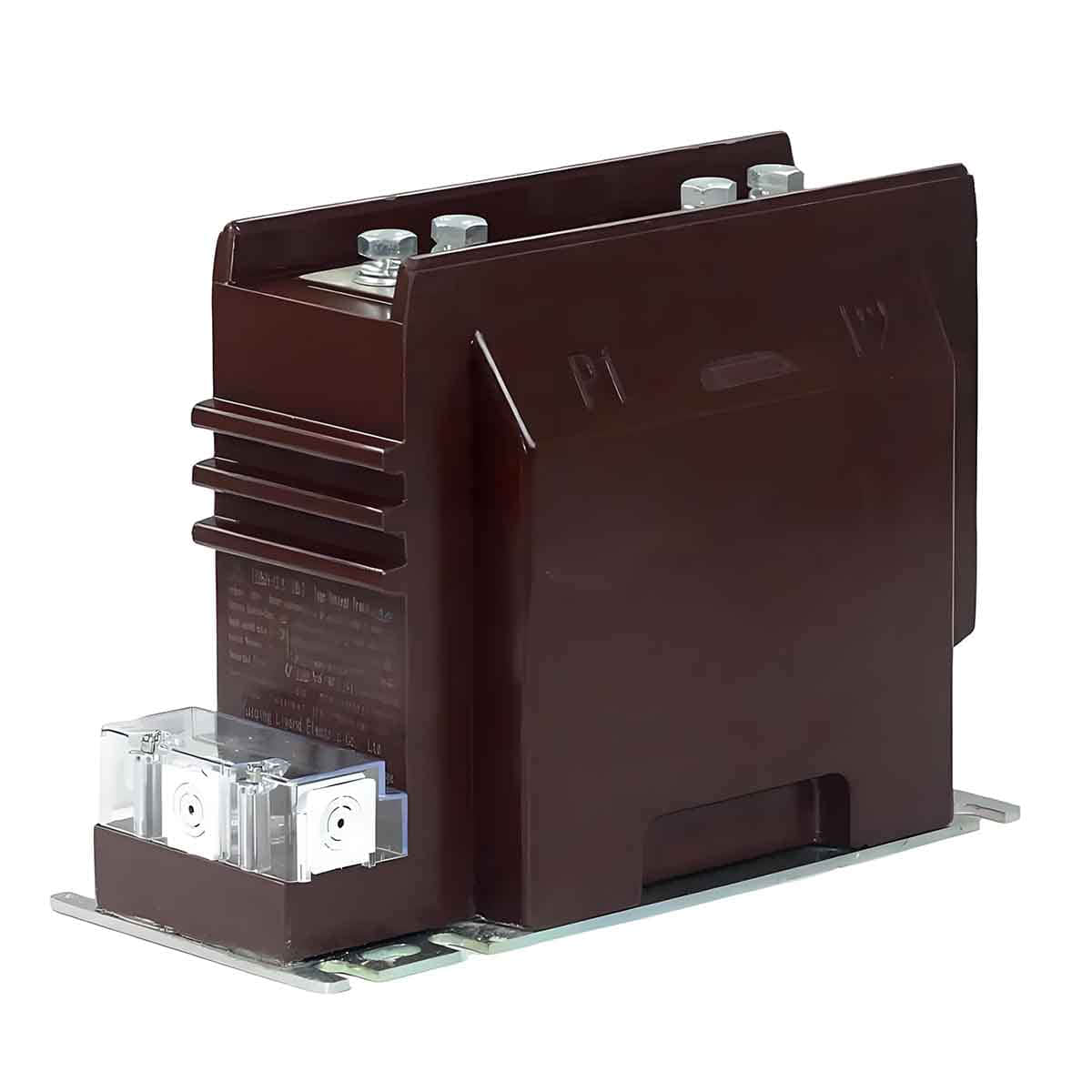
A current transformer, often called a CT, is an instrument transformer that converts a higher AC current in a primary conductor into a lower, proportional AC current in its secondary winding.
This lower current is easier and safer for meters, relays, and monitoring equipment to handle. Common secondary ratings are 5 A or 1 A, though many modern compact monitoring systems use millivolt or other interface formats through associated electronics.
For example, a 400:5 CT means that when 400 A flows in the primary conductor, 5 A flows in the secondary under rated conditions. That proportional relationship is what allows reliable current measurement at levels far above what a measuring device could safely accept directly.
CTs are widely used because they offer galvanic isolation, strong reliability, simple installation around conductors or busbars, and low cost compared with many advanced DC-capable sensors.
In utility and industrial systems, they are standard components in switchboards, motor control centers, panelboards, feeder circuits, generators, and protection cabinets.
Current transformer working principle
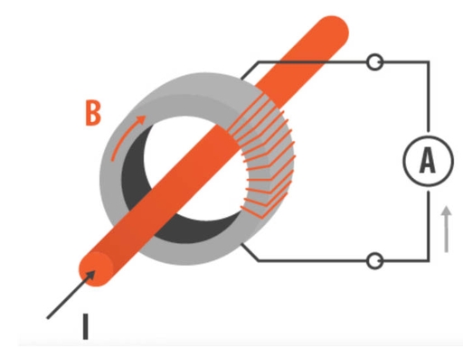
The current transformer working principle is based on electromagnetic induction. When AC current flows through the primary conductor, it creates a changing magnetic field in the CT core.
That changing magnetic field produces a changing magnetic flux. The changing flux links the secondary winding and induces a proportional current there.
This is the same fundamental transformer physics used in voltage transformers and power transformers, but optimized for current measurement. The exact output depends on turns ratio, core material, burden, frequency, and whether the CT stays within its linear operating range.
In practice, a CT may have a single-turn primary, where the actual power conductor simply passes through the core window. The secondary winding then contains many turns, establishing the ratio relationship.
Because the CT relies on changing flux, waveform shape matters. Sinusoidal AC is the classic case, but non-sinusoidal current that still changes over time can also produce a measurable output, as long as there is an AC component.
How AC enables current transformer AC operation
Alternating current rises, falls, and reverses direction. That continual change in current creates the changing magnetic flux required for transformer action.
At standard utility frequencies such as 50 Hz and 60 Hz, CTs perform extremely well when correctly selected. This is why they dominate in building distribution, industrial feeders, and power system protection.
Even distorted AC waveforms from variable loads still contain changing components. A properly specified CT can respond to those components, though overall measurement accuracy depends on core design, frequency response, and metering method.
Why current transformers do not work with DC
This is the key point behind why current transformers do not work with DC. A steady DC current creates a magnetic field that becomes constant after the switching moment.
Once the magnetic flux is no longer changing, there is essentially no induced secondary current. In other words, the CT may react briefly when the DC is first applied or removed, but then the secondary output collapses to nearly zero under steady-state DC conditions.
That is why a standard CT cannot reproduce the actual magnitude of continuous DC current. It is not a calibration issue. It is a fundamental physics limitation of the sensing principle.
There is another practical concern: steady DC can drive magnetic cores toward saturation. Even before any useful measurement is considered, the sensor behavior becomes unsuitable for normal CT metering assumptions.
Can current transformers measure DC?
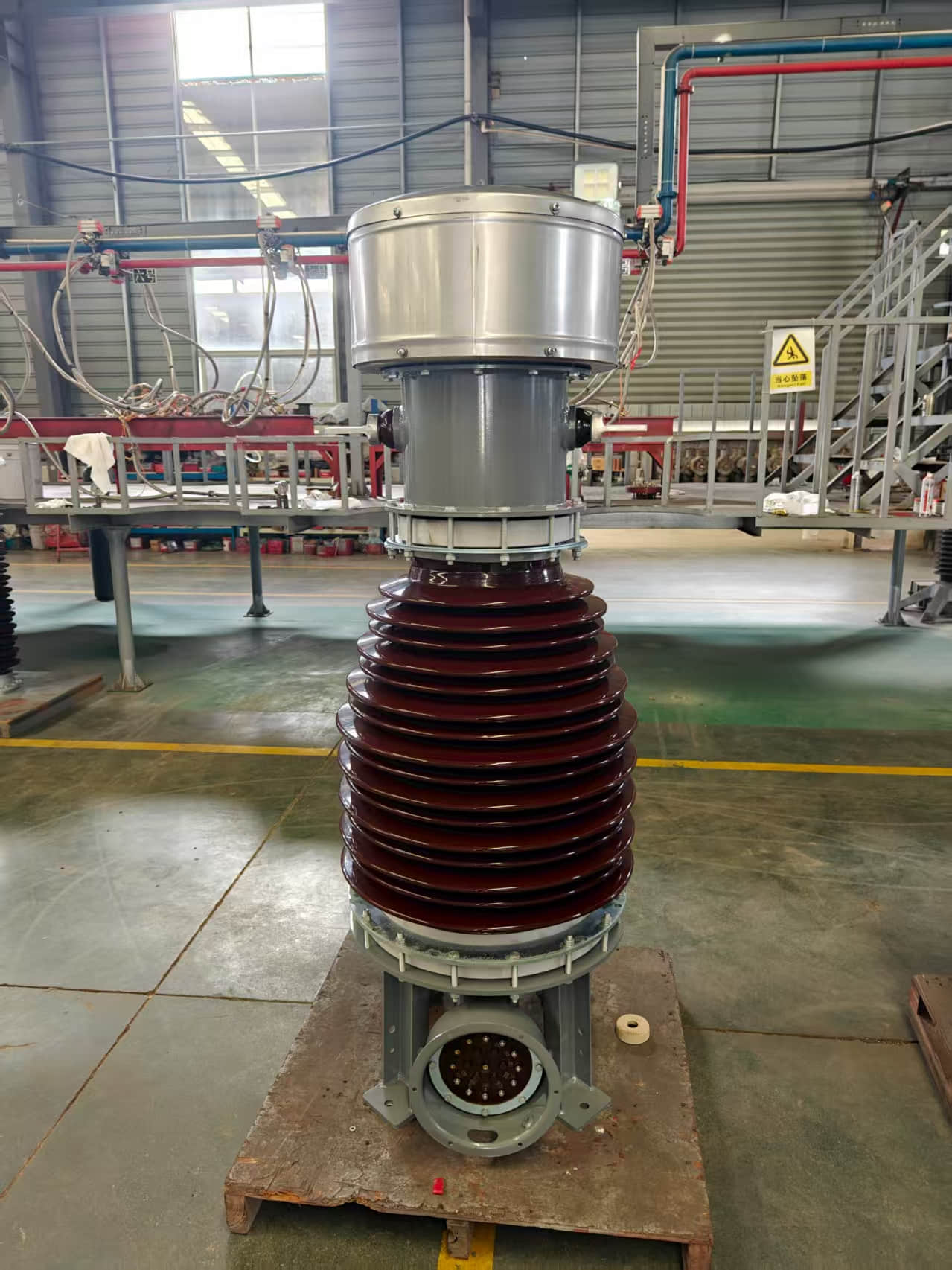
No, standard current transformers cannot accurately measure continuous DC current. They are intended for AC and AC-dominant signals.
If DC current contains ripple, switching edges, or transient changes, a CT may respond to those changing portions. That can mislead people into thinking it “measures DC,” when in fact it is only detecting the time-varying component.
For example, on a DC line feeding a converter, a CT might show activity associated with PWM ripple or switching transients. But it will not report the true steady DC baseline current in the way a Hall-effect sensor, shunt resistor, or fluxgate sensor can.
So when someone asks, can current transformers measure DC, the practical answer is: not the steady DC value you actually care about.
AC current sensor vs DC current sensor
The comparison between an AC current sensor vs DC current sensor starts with operating principle. CTs and Rogowski coils depend on changing current or changing flux. Hall-effect, shunt, and fluxgate methods can measure DC directly.
A current transformer is often the best choice for AC-only systems because it is simple, isolated, durable, and cost-effective. It is especially strong in 50/60 Hz distribution networks and traditional protection systems.
A Hall-effect sensor detects magnetic field directly, so it can measure both AC and DC. These sensors are common in EVs, battery systems, motor drives, and solar storage.
A shunt resistor measures current through voltage drop. It can measure AC or DC, offers excellent linearity, and is often very accurate, but it lacks inherent isolation unless combined with isolated signal conditioning.
A fluxgate sensor is typically used where high DC accuracy, low drift, and precision over wide dynamic ranges are required. These are common in advanced battery testing, laboratory equipment, precision drives, and high-end energy systems.
The right choice depends on waveform, current magnitude, available space, temperature range, safety isolation, EMC conditions, and budget.
Current transformer vs DC sensing technologies
| SENSOR TYPE | MEASURES AC | MEASURES DC | ACCURACY RANGE | ISOLATION | COST LEVEL | COMMON APPLICATIONS |
|---|---|---|---|---|---|---|
| Current Transformer (CT) | Yes | No for steady DC | Typically 0.1% to 3% depending on class and burden | Excellent galvanic isolation | Low to medium | Utility metering, protection relays, AC feeders, motor monitoring |
| Hall-effect Sensor | Yes | Yes | Typically 0.5% to 2%; better in premium models | Good isolation in many designs | Medium | EV systems, inverters, battery packs, chargers, mixed waveforms |
| Shunt Resistor | Yes | Yes | Can be better than 0.1% with proper design | No inherent isolation | Low | Battery management, power supplies, test benches, DC distribution |
| Fluxgate Sensor | Yes | Yes | Very high precision, often <0.1% | Typically isolated | High | Precision DC metering, laboratory instruments, high-end drives |
| Rogowski Coil | Yes | No for steady DC | Good for wide AC ranges; depends on integrator | Excellent isolation | Medium | Large AC busbars, transient capture, harmonic studies |
Real-world examples of where current transformers are used
Current transformers are everywhere in AC infrastructure, and for good reason. They solve a real measurement problem safely and economically.
Utility metering is one of the most familiar examples. In commercial service entrances, CTs step high line current down to values suitable for revenue meters or submeters. Utilities and metering contractors rely on CT accuracy classes because billing depends on stable, repeatable performance.
Motor protection is another major use case. Three-phase motors in pumping stations, HVAC plants, compressors, and conveyors are routinely monitored using CTs tied to overload relays or protective relays. The CT allows continuous observation of running current, imbalance, and fault conditions.
Switchgear monitoring is a classic application. Medium-voltage and low-voltage switchboards use CTs to feed ammeters, multifunction power meters, and relay inputs. In these environments, electrical isolation and proven fault performance matter more than novelty.
Panelboard energy analytics has grown quickly over the last decade. Split-core CTs are now commonly retrofitted in commercial buildings for branch circuit monitoring, tenant submetering, and load profiling. Installation can often be done without disconnecting major conductors, which saves labor and downtime.
In real facilities, this is not theoretical. A 2023 office retrofit might use dozens of split-core CTs to monitor lighting, HVAC, and plug loads by floor. The resulting data helps identify demand peaks and wasted overnight consumption.
Generator systems also use CTs extensively. On standby generators and synchronizing gear, CTs provide the current inputs needed for load sharing, protection, and operator visibility.
Industrial process plants use CTs in feeder monitoring. Steel plants, food processing lines, water treatment sites, and data centers all depend on accurate AC current visibility.
Manufacturers such as Weisho Electric are relevant in these scenarios because selection quality matters. In practical procurement, buyers are not just looking for “a CT”; they need the right ratio, window size, class, thermal rating, and installation style for the actual panel and load profile.
Real-world examples where a current transformer is the wrong choice
There are also many cases where a current transformer looks convenient but is technically wrong.
DC busbars are a common example. In battery energy storage systems, the DC bus between battery racks and inverters carries current that may be largely steady or slowly varying. A standard CT cannot report the true DC magnitude.
Solar battery storage is another mismatch. On the AC side of the inverter, CTs are excellent. On the DC battery string or combiner output that needs true DC monitoring, they are not.
EV battery packs absolutely require DC-capable sensing. State of charge calculations, charge/discharge control, and safety monitoring depend on accurate current integration over time. A CT cannot supply the steady-current data needed there.
Electroplating lines are strongly DC-oriented processes. Their process quality depends on controlled DC. A CT may detect ripple, but not the actual process current that operators must regulate.
DC telecom power systems, typically 48 V DC architectures, also call for DC-capable sensors. Operators need current information for battery backup health, rectifier loading, and branch monitoring.
High-current charger outputs are another area where mistakes happen. If a DC fast charger output stage is being monitored, use a DC-capable technology. If the charger’s upstream AC feed is being monitored, then a CT may be exactly right.
This distinction sounds obvious when stated clearly, yet it is one of the most common sourcing mistakes in mixed AC/DC projects.
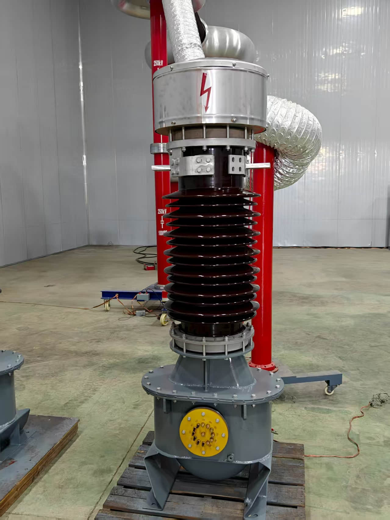
AC and DC measurement suitability by application
| APPLICATION | WAVEFORM TYPE | RECOMMENDED SENSOR | TYPICAL CURRENT RANGE | REASON FOR SELECTION |
|---|---|---|---|---|
| Commercial building feeder metering | 50/60 Hz AC | Current Transformer | 50 A to 4000 A | Low cost, isolation, proven metering performance |
| Motor protection in MCC | AC with possible harmonics | Current Transformer | 10 A to 1200 A | Compatible with relays and overload protection schemes |
| Battery energy storage DC bus | DC with ripple | Hall-effect or fluxgate sensor | 50 A to 5000 A | Must measure steady DC and dynamic current |
| EV battery pack monitoring | DC and transient current | Hall-effect or shunt | 50 A to 1500 A | Supports charge/discharge control and coulomb counting |
| Solar inverter AC output | AC | Current Transformer | 20 A to 1000 A | Measures exported AC current efficiently |
| Solar battery string | DC | Hall-effect or shunt | 10 A to 800 A | Needs true DC current reading |
| 48 V telecom distribution | DC | Shunt or Hall-effect sensor | 5 A to 600 A | Steady DC branch monitoring required |
| Arc furnace or transient AC monitoring | Rapidly changing AC | Rogowski coil or specialized CT | 500 A to 50 kA | Wide dynamic range and transient response |
Proof from practical behavior and field data
Field behavior strongly confirms the theory. In 50/60 Hz metering, well-matched CTs routinely deliver dependable performance across large installed bases in buildings, factories, and utility systems.
IEC and IEEE metering classes exist precisely because CTs are established, standardized AC measurement devices. Accuracy classes such as 0.1, 0.2, 0.5, 1.0, or relay classes such as 5P and 10P are not abstract labels; they reflect real expected performance under specified burdens and conditions.
Utilities worldwide still rely heavily on CT-based current measurement on AC distribution networks. In medium-voltage substations, relay-class CTs remain essential for overcurrent, differential, and earth fault protection.
Practical commissioning tests also show the DC limitation immediately. If a standard CT is clamped around a conductor carrying pure steady DC, the output shows only a brief transient when the current turns on or changes. After that, the steady-state signal falls essentially to zero.
This has been observed repeatedly in lab benches, field troubleshooting, and training demonstrations. The behavior is not subtle.
Another useful observation comes from variable frequency drive systems. On the drive’s AC input side, CTs can monitor supply current. On the DC link inside the drive system, they cannot provide the true DC bus current unless the waveform contains measurable ripple and even then the reading would not represent the actual DC value.
One more practical point: many modern building monitoring systems use split-core CTs with current ranges from 100 A to 600 A on branch and feeder circuits. In those applications, the technology is mature, installation is fast, and cost per point is attractive.
By contrast, battery systems often specify Hall sensors or precision shunts because the measured quantity is cumulative DC current over time, which CTs simply cannot deliver.
Common mistakes when selecting a current transformer
Some sensor mistakes are so common that they deserve a checklist.
Using CTs on battery circuits. If the line carries steady DC, a standard CT is the wrong sensor.
Leaving the CT secondary open-circuited. This is dangerous. An open secondary on an energized CT can develop hazardous voltage and damage equipment or injure personnel.
Ignoring burden limits. Excessive burden degrades accuracy and can push the CT outside intended performance.
Choosing the wrong ratio. Oversized CT ratios reduce low-load resolution; undersized ratios risk saturation or overload.
Forgetting accuracy class requirements. Revenue metering and protection need different CT classes.
Assuming all AC waveforms are equally easy. Harmonics, high crest factors, and unusual frequencies can affect results.
Ignoring installation environment. Heat, vibration, limited panel space, and EMC conditions matter.
Using a metering CT where a protection CT is required. Their behaviors under fault conditions differ.
Confusing DC ripple detection with DC measurement. A CT may react to ripple, but that does not mean it is reporting the true DC level.
Experienced suppliers can help avoid these issues early. That is one reason buyers often work with established manufacturers such as Weisho Electric when selecting AC current measurement components for panels, switchgear, and energy monitoring systems.
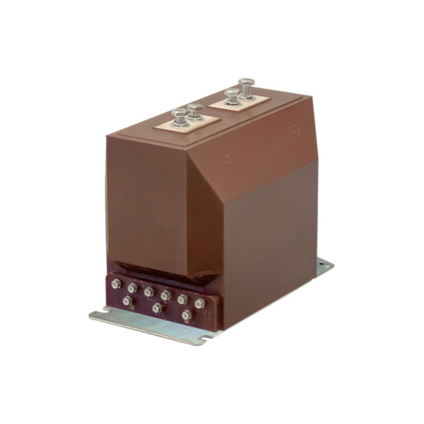
How to choose the right current transformer
Start with the most important question: what is the waveform? If it is standard AC, a current transformer is likely a strong candidate. If it is steady DC, move immediately to Hall-effect, shunt, or fluxgate options.
Next, define the current range. Consider normal load, overload, inrush, and fault conditions. A CT should not be selected solely on nameplate current.
Then look at frequency. Most CTs are optimized for 50/60 Hz, though some designs support broader ranges. If the current includes strong harmonics or high-frequency components, verify performance data.
Check isolation needs. CTs are excellent where galvanic isolation is mandatory and direct electrical connection to the monitored conductor is undesirable.
Define the accuracy class. Revenue metering, energy analytics, motor monitoring, and relay protection do not all require the same class.
Review the installation environment. Window size, busbar geometry, split-core versus solid-core construction, ambient temperature, enclosure space, and wiring distance all affect the right selection.
Finally, confirm the secondary interface. Is the connected device expecting 5 A, 1 A, or a different signal via associated electronics? Mismatches here are common in retrofit work.
A short decision framework is useful:
Is the measured current AC, DC, or mixed?
If AC, what frequency and harmonic content are present?
What are nominal, peak, and fault current levels?
What accuracy class is required?
Is galvanic isolation required?
What installation format is practical?
What device will receive the measurement output?
Quick answer summary
Current transformers are AC sensors, not steady DC sensors. They work by electromagnetic induction, which requires changing magnetic flux produced by alternating or varying current.
Standard current transformers cannot measure continuous DC accurately because steady DC creates no ongoing change in flux, so the secondary output falls to nearly zero after a brief transient. For DC measurement, use Hall-effect, shunt-based, or fluxgate sensing technology.
FAQ
Are current transformers used for AC only?
Yes, standard current transformers are intended for AC and AC-dominant waveforms. They rely on changing current to induce a proportional secondary signal, which is why they are widely used in 50/60 Hz power systems, metering, and protection.
Can current transformers measure DC current accurately?
No, standard CTs cannot measure steady DC current accurately. If your application involves battery packs, DC buses, telecom power, or charger outputs, use a Hall-effect sensor, shunt resistor, or fluxgate sensor instead.
Why do current transformers do not work with DC?
They do not work with steady DC because transformer action requires changing magnetic flux. Once DC becomes constant, the magnetic field stops changing, so the secondary winding no longer produces meaningful induced current.
What happens if a current transformer is connected to DC?
It may show a brief transient when the DC current is switched on, switched off, or changes suddenly. After that, it will not provide a useful steady-state output corresponding to the real DC current value.
What sensor should be used instead of a current transformer for DC?
For DC measurement, use a Hall-effect sensor when you want isolation and practical system integration, a shunt-based sensor when high accuracy and low cost are priorities, or a fluxgate sensor when precision and low drift are critical.
Can a current transformer measure pulsed or mixed currents?
It can detect the changing or AC component of pulsed or mixed currents. However, it cannot correctly reproduce the true steady DC component, so it should not be used where total DC level is the measurement target.
Is a Hall-effect sensor better than a current transformer?
It is better for DC or mixed AC/DC signals. For AC-only systems, however, CTs are often simpler, more economical, highly reliable, and very well suited to metering and protection tasks.
Are Rogowski coils AC or DC sensors?
Rogowski coils are also AC or transient current sensors. Like CTs, they depend on changing current and therefore cannot measure steady DC directly.
Conclusion: Are current transformers AC or DC?
The verdict is clear: a current transformer is an AC device. Its operating principle depends on changing magnetic flux, which alternating current naturally provides and steady DC does not.
That is why current transformers are outstanding for utility metering, switchgear, motor protection, and building energy analytics on AC systems. It is also why they are the wrong choice for battery strings, DC busbars, EV packs, and other steady-DC applications.
If you remember just one line, make it this: use CTs for AC, and use DC-capable sensing technology for DC.
CTA
Before you specify your next current sensor, compare the actual waveform, current range, isolation requirement, accuracy target, and installation environment. That one step can prevent costly redesigns and unreliable measurements.
If your project involves AC metering, protection, panel monitoring, or a mixed AC/DC architecture, get expert help and select the sensor technology that truly fits the job. Review your application carefully, shortlist the right options, and request professional support now to ensure safe, accurate, and future-ready current measurement.